

Page 1
Instruction Manual for P26
Differential Pressure
Transducer
halstrup - walcher GmbH
Stegener Strasse 10
D-79199 Kirchzarten
GERMANY
Phone:+49 (7661) 39 630
Fax: +49 (7661) 396 399
E-Mail: info@halstrup-walcher.com
Internet: www.halstrup-walcher.com
Document 7100.004084C Version 4.2 02/2015
Page 2

P26 Instruction Manual
2
Table of Contents:
1 Purpose of instruction manual ............................................................................................. 4
2 Safety precautions ............................................................................................................... 5
2.1 Appropriate use .............................................................................................................. 5
2.2 Shipping, assembly, electrical connections and startup .................................................. 5
2.3 Troubleshooting, maintenance, repairs, disposal ............................................................ 5
2.4 Symbols ......................................................................................................................... 6
3 Instrument description ......................................................................................................... 7
3.1 Features ......................................................................................................................... 7
3.2 User interfaces ............................................................................................................... 8
3.3 Internal ports and keys ................................................................................................... 9
3.4 Front view .................................................................................................................... 12
4 Zero-point calibration cycle ................................................................................................ 13
5 Overpressure protection .................................................................................................... 13
6 Display (optional) ............................................................................................................... 13
7 Menu (optional) ................................................................................................................. 13
7.1 Display ......................................................................................................................... 14
7.2 Scale ............................................................................................................................ 14
7.2.1 Pressure ................................................................................................................. 14
7.2.1.1 Top ............................................................................................................... 14
7.2.1.2 Bottom .......................................................................................................... 14
7.2.1.3 Unit .............................................................................................................. 14
7.2.2 Volumetric flow ....................................................................................................... 15
7.2.2.1 Value ............................................................................................................ 15
7.2.2.2 Unit .............................................................................................................. 15
7.2.3 Mass flow ................................................................................................................ 15
7.2.3.1 Value ............................................................................................................ 15
7.2.3.2 Unit .............................................................................................................. 15
7.2.4 Flow rate ................................................................................................................. 15
7.2.4.1 Value ............................................................................................................ 15
7.2.4.2 Unit .............................................................................................................. 16
7.3 Warning........................................................................................................................ 16
7.3.1 Value ...................................................................................................................... 16
7.3.2 Hysteresis ............................................................................................................... 16
7.3.3 TV delay time .......................................................................................................... 16
7.3.4 TN hold time ........................................................................................................... 16
7.3.5 Warning signal ........................................................................................................ 16
Page 3

P26 Instruction Manual
3
7.3.6 Filter ........................................................................................................................ 17
7.3.7 Mode ....................................................................................................................... 17
7.4 Settings ........................................................................................................................ 17
7.4.1 Language ................................................................................................................ 17
7.4.2 Output ..................................................................................................................... 17
7.4.3 Filter ........................................................................................................................ 17
7.4.4 Warning signal ........................................................................................................ 17
7.4.5 Resolution ............................................................................................................... 18
7.4.6 Zero-point calibration .............................................................................................. 18
7.4.7 CS (creep suppression) .......................................................................................... 18
7.4.8 Read factory settings .............................................................................................. 18
7.4.9 Code? ..................................................................................................................... 18
8 Serial interface (optional) ................................................................................................... 18
8.1 Settings ........................................................................................................................ 18
8.2 USB ............................................................................................................................. 18
8.3 List of commands ......................................................................................................... 19
9 Technical data ................................................................................................................... 21
10 Troubleshooting ............................................................................................................... 21
11 Dimension drawing .......................................................................................................... 22
12 Menu tree ........................................................................................................................ 23
Page 4

P26 Instruction Manual
4
1 Purpose of instruction manual
This instruction manual describes the features of the P26 and provides guidelines for its use.
Improper use of this instrument or failure to follow these instructions may cause injury or
equipment damage. Every person who uses this device must therefore read the manual and
understand the possible risks. The instruction manual, and in particular the safety precautions
contained therein, must be followed carefully.
Contact the manufacturer if you do not understand any part of this instruction manual.
Handle this manual with care:
It must be readily available throughout the lifecycle of the instrument.
It must be provided to any individuals who assume responsibility for operating the
instrument at a later date.
It must include any supplementary materials provided by the manufacturer.
The manufacturer reserves the right to continue developing this instrument model without
documenting such development in each individual case. The manufacturer will be happy to
determine whether this manual is up-to-date.
Conformity
This device is state of the art. It complies with the legal requirements of EC directives.
This is shown by the CE mark.
© 2012,2015
The manufacturer owns the copyright to this instruction manual. It contains technical data,
instructions and drawings detailing the device’s features and how to use it. It must not be copied
either wholly or in part or made available to third parties.
Page 5

P26 Instruction Manual
5
2 Safety precautions
2.1 Appropriate use
The P26 is used to measure pressure, volumetric flow, mass flow and flow rate.
Always observe the operating requirements—particularly the permissible supply voltage—
indicated on the rating plate and in the “Technical data” section of this manual.
The instrument may only be handled as indicated in this manual. Modifications to the
instrument are prohibited. The manufacturer is not liable for damages caused by improper use
or failure to follow these instructions. Violations of this type render all warranty claims null and
void.
2.2 Shipping, assembly, electrical connections and startup
Do not close the pressure inlets during shipping. Changes in barometric pressure may
damage devices with low measuring ranges.
Assembly and the electrical connections should only be handled by professionals. They should
be given proper training and be authorised by the operator of the facility.
The instrument may only be operated by appropriately trained individuals who have been
authorized by the operator of the facility.
Do not carry out a function test with compressed or breathable air. This would damage
instruments with low measuring ranges.
Measurement errors may occur if the instrument is not kept protected from sunlight.
Specific safety precautions are given in individual sections of this manual.
2.3 Troubleshooting, maintenance, repairs, disposal
The individual responsible for the electrical connections must be notified if the instrument is
damaged or if errors occur that cannot be corrected as indicated in Section 10.
This individual must take the instrument out of service until the error has been corrected and
ensure that it cannot be used unintentionally.
Always unplug the power cord before opening the instrument!
This instrument requires no maintenance.
Only the manufacturer may perform repairs that require the housing to be opened.
The electronic components of the instrument contain environmentally hazardous materials and
materials that can be reused. The instrument must therefore be sent to a recycling plant when
you no longer wish to use it. The environment codes of your particular country must be
complied with.
Page 6
P26 Instruction Manual
6
2.4 Symbols
The symbols given below are used throughout this manual to indicate instances when
improper operation could result in the following hazards:
WARNING! This warns you of a potential hazard that could lead to bodily injury up to
and including death if the corresponding instructions are not followed.
CAUTION: This warns you of a potential hazard that could lead to significant property
damage if corresponding instructions are not followed.
INFORMATION: This indicates that the corresponding information is important for
operating the instrument properly.
Page 7
P26 Instruction Manual
7
3 Instrument description
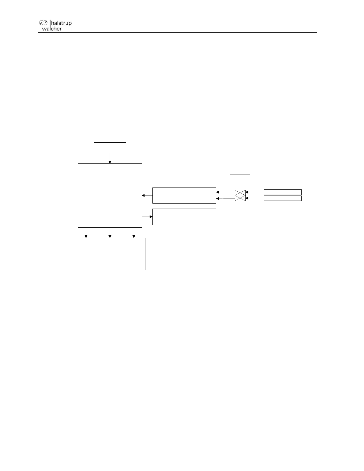
3.1 Features
The P26 is controlled by a microprocessor and can perform the following tasks:
Measurement of pressure and vacuum
Measurement of differential pressure
Measurement of volumetric flow, mass flow and flow rate
Display of a measured value
Monitoring of a variety of threshold parameters
-
+
Actual pressure value
Calculation:
Volumetric flow
Mass flow
Flow rate
µC
Pressure measurement
Valves
Pressure
Vacuum
Display
Serial
interface
Relay
Keyboard
Analogue output signal
Fig. 1: Basic circuit diagram
Page 8

P26 Instruction Manual
8
3.2 User interfaces
There are four keys:
Key
Meaning (Measurement Mode)
Meaning (Menu)
Menu
Start Menu
Go back a menu level
Enter
Start zero point calibration
Confirm
Up
Max. display
Increase value or scroll up
Right
Min. display
Move the cursor or scroll down
In measurement mode, the keys perform the following functions:
The Enter key starts a zero point calibration
“^“ key shows the maximum (to reset: press Enter while the maximum is being displayed)
“>“ key shows the minimum (to reset: press Enter while the minimum is being displayed)
Page 9

P26 Instruction Manual
9
3.3 Internal ports and keys
Standart version
with external zero point calibration
Page 10

P26 Instruction Manual
10
Standard-Version
Output signal Relay 1 Relay 2 Power supply
RS232 interface for PC Reset
Version mit externer Nullierung
Output signal Relay 1 Relay 2 Power supply
ext. offset calibration
RS232 interface for PC Reset
Page 11

P26 Instruction Manual
11
Output signal:
Relay 1:
Relay 2:
Power supply:
without transformer
o 24V DC
contact 11 => Ground
contact 12 => +24V DC
o 24V AC
contact 11 => Ground
contact 12 => +24V AC
with transformer
o 115V AC
contact 12 and 13
o 230V AC
contact 11 and 13
o 24V AC
contact 11 and 13
RS232 interface for PC:
RS232 or USB-Interface interface for parameter settings
Reset: The processor is restarted.
Port description
Description
1 OUT_I
Current output
2 OUT_GND
Earth
3 OUT_U
Voltage output
Z ZERO-Calibr.(Option)
+24V -> ext. zero calibration
Port description
Description
4 REL1_NO
Normally open contact
5..REL1_C
Central contact
6 REL1_NC
Normally closed contact
Port description
Description
7 REL2_NC
Normally closed contact
8 REL2_C
Central contact
9 REL2_NO
Normally open contact
Page 12

P26 Instruction Manual
12
3.4 Front view
RS -232 or USB(optional) Cable bushings:
Signal Relay Power supply
Pressure ports: + -
RS-232:
Port description
PIN
Description
RXD
3
Reception
TXD
2
Send
GND
5
Earth
USB:
Port description
PIN
Description
Power
1
Power supply for USB from PC
D- bidirectional
2
USB Data, negative polarity
D+ bidirectional
3
USB Data, positive polarity
ID 4 not used
Ground
5
GND = USB Signalground
Case Ground
shield
Shielding over PC
INFORMATION:
The best measuring accuracy is achieved at a room temperature of 20°C.
Page 13

P26 Instruction Manual
13
4 Zero-point calibration cycle
External influences such as temperature, position or ambient pressure can shift the instrument’s
zero point, i.e., the value displayed when the pressure ports are open. Calibration is the process
by which the instrument automatically registers this shift and figures it into the currently
displayed pressure value. The zero-point calibration is performed in two stages, which are
shown in the top line on the display (optional).
“ 0” Measuring signal of the zero point is being determined.
“ P” Pressure is being reconfigured
The interval between two zero-point calibrations can be adjusted in the Settings menu.
Zero-point calibration can also be started with the Enter key if the device is in Measurement
mode.
The P26 does not respond to keys being pressed during calibration.
4.1 External zero-point calibration(Option)
The ext. zero-point calibration is available as an Option. To initiate an ext. zero-point calbration,
the extra pin on the output connector must be connected to +24 V.
INFORMATION:
If a zero-point calibration is initiated via the serial interface or optional ext. zero-point
calibration, this will still be carried out. In this case, it doesn’t matter if the zero-point
calibration is deactivated or the P26 is in the menu.
5 Overpressure protection
The P26 has an internal overpressure safeguard that protects the precision pressure
measurement capsule from damage. (Overload range: 200 x [max. 600 kPa])
6 Display (optional)
The measured values and the menu are shown on the display. The top line is the information
line. This line displays the type of measured value or the status of a zero-point calibration. The
measurement value will be displayed on the central line. If the permitted measuring range is
exceeded or not reached, the figures are replaced by corresponding arrows. The bottom line
displays the unit, with the first two digits showing the status of the two relays.
7 Menu (optional)
If the P26 includes a display, you can use the menu to adjust various settings. Press the Menu
key to bring up the menu.
In Menu mode, the parent menu item always appears in the top display line. The middle line
always shows the current sub-menu item or value to be changed. The bottom line displays units
or other help texts.
Start the Menu mode by pressing the "Menu" key. It can be protected with a four-character
password. At the main menu level, “Menu” is displayed in the top line and “Display” in the
middle line. Select your desired sub-menu by pressing the “^” and “>” keys. Press “Enter” to go
to a sub-menu or enter a value. Press the “Menu” key to go to the next menu level or to stop
entering values.
Page 14

P26 Instruction Manual
14
7.1 Display
The display unit can be selected with this menu item. Press the “^” and “>” keys to select the
unit you want and press “Enter” to confirm. The type of display (pressure, flow rate etc.) is
selected automatically.
7.2 Scale
The P26 is usually supplied with standard measuring ranges. You can use the scale to adjust
the measuring range for your own use. The output voltage or currents are then copied to this
scaled range. The scaled range should always be more than 0.1 times of that of the P26’s
measuring range, because otherwise the resolution of the outputs and the accuracy will be
poorer.
With this menu item, there are 4 sub-menu items:
Pressure
Volumetric flow
Mass flow
Flow rate
7.2.1 Pressure
This is an important menu item. It is used to specify the pressure range, which indicates the
output value. This pressure range forms the basis for many other settings such as the limits for
the relays (warnings) and factors for the flow display.
There are two default settings for the pressure scale:
Top = Pressure at which the output has its maximum value (e.g. 5V, 10V or 20 mA)
Bottom – Pressure at which the output has its minimum value (e.g. -5V, 0V, 0mA or 4mA)
Because the values can be freely assigned, settings such as 0V at 0Pa or 10V at -250Pa are
also possible.
7.2.1.1 Top
With this menu item, you can set the pressure at which the output will achieve its maximum
value. Any value within the measuring range can be selected. It can also be less than the
lower scale value.
7.2.1.2 Bottom
With this menu item, you can set the pressure at which the output will achieve its minimum
value. Any value within the P26’s measuring range can be selected.
7.2.1.3 Unit
Use this menu item to select the pressure unit. The following pressure units can be selected:
Pa
hPa
kPa
Mbar
mmH2O
mmHg
Psi
inH2O
inHg
Page 15

P26 Instruction Manual
15
7.2.2 Volumetric flow
This menu item is used to adjust the volumetric flow display values.
The following sub-menu items are available:
Value
Unit
7.2.2.1 Value
This is used to set the volumetric flow value displayed at the maximum scaled pressure. 0 is
always used as the lower scale value on the volumetric flow display (root-extracted measured
value). The maximum pressure is the larger of the two scale values, which is used as a basic
calculation.
7.2.2.2 Unit
You can use this menu item to select the unit of the volumetric flow value. The following
volumetric flow units can be selected: m3/s, m3/h
7.2.3 Mass flow
This menu item is used to adjust the mass flow display values.
The following sub-menu items are available:
Value
Unit
7.2.3.1 Value
This is used to set the mass flow value displayed at the maximum scaled pressure. 0 is always
used as the lower scale value on the mass flow display (root-extracted measured value). The
maximum pressure is the larger of the two scale values, which is used as a basic calculation.
7.2.3.2 Unit
You can use this menu item to select the mass flow unit. The following mass flow units can be
selected: kg/s, kg/min, kg/h
7.2.4 Flow rate
This menu item is used to adjust the flow rate display values.
The following sub-menu items are available:
Value
Unit
7.2.4.1 Value
This is used to set the flow rate value displayed at the maximum scaled pressure. 0 is always
used as the lower scale value on the flow rate display (root-extracted measured value). The
maximum pressure is the larger of the two scale values, which is used as a basic calculation.
Page 16

P26 Instruction Manual
16
7.2.4.2 Unit
Use this menu item to select the flow rate unit. The following flow rate units can be selected:
m/s, mph, f/s, f/min, km/h
7.3 Warning
Use this menu item to influence the behaviour of the relays. The first menu item that appears
here is Select Relay. The settings for this relay should then be changed. Use the “^” and “>”
keys to select the number of the relay and press Enter to move to that relay's menu.
The following sub-menu items are available:
Value
Hysteresis
TV
TN
Warning signal
Filter
Mode
7.3.1 Value
This item adjusts the pressure value at which the particular relay should switch. The pressure
range defined by the scale can be used as the setting range. Select the pressure unit set for
the display as the unit. If the volumetric flow, mass flow or flow rate (root-extracted display) is
displayed, select the Pa unit.
7.3.2 Hysteresis
This item can be used to select the hysteresis for the particular relay. The action described in
7.3.1 applies to the entry unit. The hysteresis is always positive.
7.3.3 TV delay time
With this parameter, you can now specify how long the pressure value can be exceeded or not
met until the relay switches. The adjustment is done in ms.
7.3.4 TN hold time
With this parameter, you can now specify how long the pressure value may fall below the limit,
until the relay switches back. The adjustment is done in ms.
7.3.5 Warning signal
If one of the limits is exceeded and the relay activated, a warning signal sounds at one-second
intervals. With this parameter, you can set the duration of this warning signal for each relay.
The maximum value here is 1000 ms (continuous tone). If both relays are active, the longer
warning signal of the two sounds. The warning signal may sound different depending on the
activation level. A warning signal duration of 0 ms switches the signal off.
Page 17

P26 Instruction Manual
17
7.3.6 Filter
Here you can specify if the unfiltered or the filtered pressure value is used as signal input for
the relays section. For each relay the filter can be switched on or off.
7.3.7 Mode
Here you can specify whether the relay is activated if the warning pressure is exceeded or not
met (relay switching direction) This affects the processing of the hysteresis value.
7.4 Settings
With this menu item, you can adjust various parameters that affect the instrument’s behaviour.
The following sub-menu items are available:
Language
Output
Filter
Warning signal
Resolution
Zero-point calibration
CS (creep suppression)
Read factory settings
Code?
7.4.1 Language
The menu language can be selected with this menu item. You can choose from the following
languages:
English
German
Italian
French
Make your choice with the “^” or ">" keys. Press Enter to confirm your selection.
7.4.2 Output
With this parameter, you can select the output and output range. You can choose from the
following options:
4…20 mA
0…20 mA
-5V…+5V
0V…10V
7.4.3 Filter
The measured pressure values can be smoothened by a filter before they reach the display or
analogue output. This parameter lets you set a time constant for this filter.
7.4.4 Warning signal
With this parameter, the signal that a key has been pressed can be switched on or off.
Page 18

P26 Instruction Manual
18
7.4.5 Resolution
This parameter affects the display resolution. The display is changed according to the adjusted
values. For example, if the setting is 1%, the display changes to showing the measuring range
in 1% jumps. This can be used with severely fluctuating pressures to steady the display.
However, this does not have any affect on the relays.
7.4.6 Zero-point calibration
This parameter specifies the time interval for the automatic zero-point calibration. The entry is
in min. Setting the parameter to 0 deactivates automatic zero-point calibration.
7.4.7 CS (creep suppression)
This parameter specifies the value for creep suppression as a percentage. If this value falls
short of the measured pressure value, the display is set to zero. Creep suppression only works
with volumetric flow, mass flow and flow rate (root-extracted measurement values).
7.4.8 Read factory settings
The factory settings are established in the instrument before delivery. With this menu item,
they can be reactivated if required.
7.4.9 Code?
You can use this menu item to specify an access code for the menu. If this code is <>0, the
access code will only be queried after the Menu key has been pressed. Only when the correct
code has been entered can you proceed to the menu. If the code = 0, this query will not be
made.
8 Serial interface (optional)
8.1 Settings
The serial interface (RS 232) has the following settings:
9600 Baud
8 data bits
No parity
One stop bit
8.2 USB
A standard USB to serial converter is used for the USB-Interface. The Drivers can be achieved
from the manufacturer at ‘www.ftdichip.com’
http://www.ftdichip.com/Drivers/CDM/CDM 202.08.24 WHQL Certified.zip
The driver will establish a new COM-Port, which can be used with the same parameter as the
RS232-Interface.
Page 19

P26 Instruction Manual
19
8.3 List of commands
Command
Description
Type
?IP
Returns the pressure value in the selected unit
(see command UnitD)
floating
?ST
Returns the status:
Bit6: relay1 switched on
Bit5: relay2 switched on
Bit2: overpressure
Bit1: zero-point calibration active
Reserved Bits: 7, 4, 3, 0
8 places
Modes
MZ
Mode Zero-Point Calibration
Parameter
Description
Type
Set: '>'par
Query: '?'par
ScalO
Scale top [Pa]
(-120% … 120% from measurement range)
floating
ScalU
Scale bottom [Pa]
(-120% … 120% from measurement range)
floating
ScalVS
Volumetric flow [m³/s] at max. scale value(Scalo)
(Min: 0)
floating
ScalMF
Mass flow [kg/s] at max. scale value(Scalo)
(Min: 0)
floating
ScalSG
Flow rate [m/s] at max. scale value(Scalo)
(Min: 0)
floating
PRelai1
Switching pressure for Relay 1 [current display unit]
(-120% … 120% from measurement range)
floating
RRelai1
Switching direction for Relay 1
(-1 = decreasing, 0 = off, 1 = increasing)
int
SRelai1
Sound for Relay 1 [ms]
(0 = Off, max. 1000ms)
HRelai1
Hysteresis relay 1 [Pa]
(0% … 120% from measurement range)
floating
TRelai1
Response time for relay 1 [msec]
(0 .. 30000)
unsigned int
ARelai1
Hold time Relay 1[ms] (ab Rev. 2.11)
(0 .. 30000)
RFilter1
Select filter or unfiltered pressure for Relay 1
(0 = Off, 1 = on);
unsigned int
PRelai2
Switching pressure for Relay 2 [current display unit]
(-120% … 120% from measurement range)
floating
RRelai2
Switching direction for Relay 2
(-1 = decreasing, 0 = off, 1 = increasing)
int
SRelai2
Sound for Relay 2 [ms]
(0 = Off, max. 1000ms)
unsigned int
HRelai2
Hysteresis for Relay 2 [current display unit]
(0% … 120% from measurement range)
floating
TRelai2
Response time for relay 2 [msec]
(0 .. 30000)
unsigned int
ARelai2
Hold time Relay 1[ms] (ab Rev. 2.11)
(0 .. 30000)
unsigned int
RFilter2
Select filter or unfiltered pressure for Relay 1
(0 = Off, 1 = on);
unsigned int
Page 20

P26 Instruction Manual
20
Parameter
Description
Type
Filter
Filter (time in ms)
25 … 60000)
unsigned int
Lang
Language
(1=GB, 2=D, 3=I, 4=F)
unsigned int
AutoNull
Automatic zero-point calibration [min]
(0=Off … 2999)
Sound
Sound
(1=On, 0=Off)
unsigned int
TSound
Sound length [msec]
(0 … 999)
unsigned int
DAC Out
Analogous output signal
(0 = 4-20mA, 1 = 0-20mA, 2 = -5 to +5V,
3 = 0-10V)
unsigned int
Res
Resolution
(0=max., 1=0.01%, 2=0.1%, 3=0.2%, 4=0.5%,
5=1%)
unsigned int
UnitD
Unit display
(0=Pa, 1=hPa, 2=kPa, 3=mbar, 4=mmH2O,
5=mmHg, 6=Psi, 7=inH2O, 8=inHg, 9=m3/s,
10=m3/h, 11=kg/s, 12=kg/min, 13=kg/h, 14=m/s,
15=mph, 16=f/s, 17=f/min, 18=km/h)
unsigned int
>Code
Access code (write only)
unsigned int
SMU
creep suppression[%]
(0 … 10)
unsigned int
RecallWE
Recall factory settings(use without > or ?)
SaveSet
Save (use without > or ?)
Page 21

P26 Instruction Manual
21
9 Technical data
Measurement data
Measurement range
See rating plate
Accuracy
0.5% +0.3 Pa of scaled range
(40…100% of end value)
Resolution
Depends on the measuring range (max. 5 relevant
places)
Ambient conditions
Medium
Air, non-aggressive gases
Operating temperature
+10 °C to +50 °C
Storage temperature
-10 °C to +70 °C
Conformity
Declaration of conformity available upon request
Electrical data
Rated input
approx. 6 VA
Supply voltage
See rating plate
Output signal
0…+10 V (RL ? 2 k Ω) or
-5…+5 V (RL ? 2 k Ω) or
0…20 mA (RL = 500 Ω) or
4…20 mA (RL = 500 Ω)
Relays
2 x change-over contacts
For each relay: 6A / 230 VAC
Interface
RS-232
9600 Baud, 8 data bits, no parity, one stop bit
USB
USB 2.0 Full-Speed
10 Troubleshooting
Problem
Cause
Corrective Action
Instrument does not work;
nothing on display
No power
Check the terminal connections
and supply voltage
Pressure drops
continuously
Leak
Firmly slide tubing completely
onto ports; adjust diameter
No serial communication
No cable connection
Secure the connection
Instrument is beeping
Limits have been exceeded or
not met
Use any key to acknowledge
Page 22

P26 Instruction Manual
22
11 Dimension drawing
147.5±1.5
56.5±1.5
25 39.5
20
92.5
162
100.5
6.5
6.5
Ø4.5
14.5
27
75
Page 23

P26 Instruction Manual
23
12 Menu tree
Level 1
Level 2
Level 3
Level 4
Display
Pressure
Pa
hPa
kPa
mbar
mmH2O
mmHg
psi
inH2O
inHg
m³/s
m³/h
kg/s
kg/min
kg/h
m/s
mph
f/s
f/min
km/h
Scaling
Pressure
Top
xxxx.x
Bottom
xxxx.x
Unit
Pa
hPa
kPa
mbar
mmH2O
mmHg
psi
inH2O
inHg
Vol. Flow
Value
xxxxxxx.x
Unit
m³/s
m³/h
Mass flow
Value
xxxxxxx.x
Einheit
kg/s
kg/min
kg/h
Flow rate
Value
xxxxxxx.x
Unit
m/s
mph
f/s
f/min
km/h
Page 24

P26 Instruction Manual
24
Level 1
Level 2
Level 3
Level 4
Warning
Relay 1
Relay 2
Value
xxxx.x
Hysteresis
xxxx.x
TV
xxxxx ms
TN(Rev2.11)
xxxxx ms
Warning signal
xxxxx ms
Filter(Rev2.14)
off, on
Mode
increasing
decreasing
Settings
Language
English
German
Italian
French
Output
4 … 20 mA
0 … 20 mA
-5 …+5V
0 … 10 V
Filter
xxxxx ms
Warning signal
on/off
on
off
Resolution
max.
0.01%
0.1%
0.2%
0.5%
1%
Zero-point
calibration
xxxx min
CS
x.x%
Read factory
settings
(Yes = Enter key
Code?
xxxx
 Loading...