

Page 1
SINGLE PAGES 20/9/10 09:58 Page 1
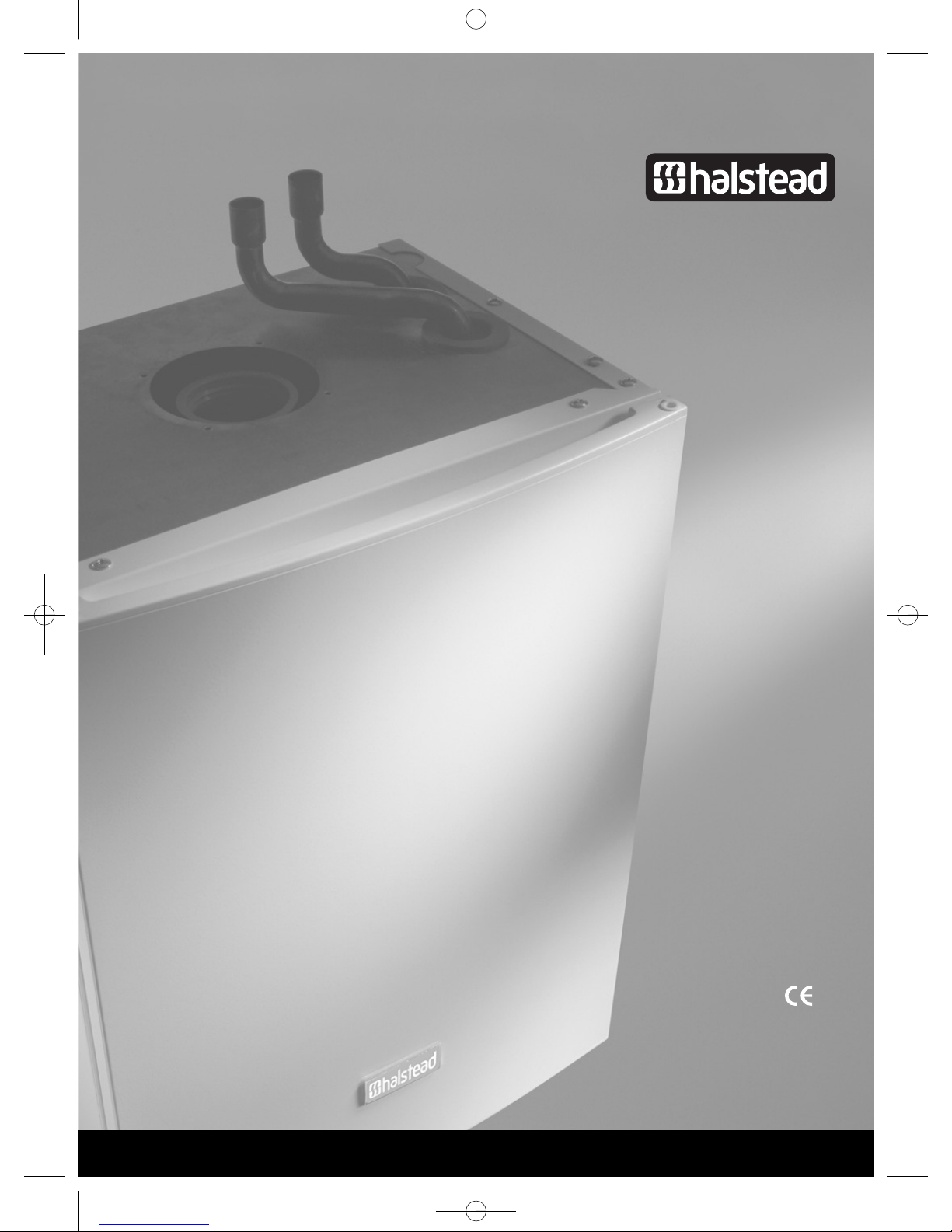
Eden X Type
VBX 18 & 30
INSTALLATION AND SERVICING INSTRUCTIONS
TO BE GIVEN TO THE USER
0086
EC 87/BP/35
G.C. Appliance No. 41-260-15 (Eden VBX 18)
G.C. Appliance No. 41-260-14 (Eden VBX 30)
G.C. Appliance No. 41-260-18 (Eden VBX 18 Propane)
G.C. Appliance No. 41-260-17 (Eden VBX 30 Propane)
OPEN VENT CONDENSING BOILER
Page 2

SINGLE PAGES 20/9/10 09:58 Page 2
CONTENTS INTRODUCTION
1 Introduction . . . . . . . . . . . . . . . . . . . . . . . . . . . . . . . . . . . . . . . . . . . . . . . . . . . 0
1.1 Important Information . . . . . . . . . . . . . . . . . . . . . . . . . . . . . . . . . . . . . . . . . . . 1
1.2 General Description . . . . . . . . . . . . . . . . . . . . . . . . . . . . . . . . . . . . . . . . . . . . . 1
INTRODUCTION
1
2 Technical Specifications . . . . . . . . . . . . . . . . . . . . . . . . . . . . . . . . . . . . . . . . . 2
2.1 Gas Categories . . . . . . . . . . . . . . . . . . . . . . . . . . . . . . . . . . . . . . . . . . . . . . . . . 2
2.2 Performance Data. . . . . . . . . . . . . . . . . . . . . . . . . . . . . . . . . . . . . . . . . . . . . . . 2
2.3 General Specifications . . . . . . . . . . . . . . . . . . . . . . . . . . . . . . . . . . . . . . . . . . . 3
2.4 Overall Dimensions & Minimum Clearances. . . . . . . . . . . . . . . . . . . . . . . . . 4
2.5 Concentric Air / Flue Duct Specifications . . . . . . . . . . . . . . . . . . . . . . . . . . . 4
2.6 Additional Concentric Flue Kits . . . . . . . . . . . . . . . . . . . . . . . . . . . . . . . . . . . 8
2.7 Appliance Hydraulic Circuit. . . . . . . . . . . . . . . . . . . . . . . . . . . . . . . . . . . . . . . 10
3 Installation Requirements . . . . . . . . . . . . . . . . . . . . . . . . . . . . . . . . . . . . . . . 11
3.1 Statutory Requirements. . . . . . . . . . . . . . . . . . . . . . . . . . . . . . . . . . . . . . . . . . 11
3.2 Appliance Location . . . . . . . . . . . . . . . . . . . . . . . . . . . . . . . . . . . . . . . . . . . . . . 11
3.3 Flue Terminal Position. . . . . . . . . . . . . . . . . . . . . . . . . . . . . . . . . . . . . . . . . . . 11
3.4 Ventilation Requirements . . . . . . . . . . . . . . . . . . . . . . . . . . . . . . . . . . . . . . . . 11
3.5 Condensate Disposal . . . . . . . . . . . . . . . . . . . . . . . . . . . . . . . . . . . . . . . . . . . . 12
3.6 Gas Supply. . . . . . . . . . . . . . . . . . . . . . . . . . . . . . . . . . . . . . . . . . . . . . . . . . . . . 12
3.7 Central Heating System . . . . . . . . . . . . . . . . . . . . . . . . . . . . . . . . . . . . . . . . . . 12
3.8 Draining Tap . . . . . . . . . . . . . . . . . . . . . . . . . . . . . . . . . . . . . . . . . . . . . . . . . . . 13
3.9 Safety Valve Open Vented System . . . . . . . . . . . . . . . . . . . . . . . . . . . . . . . . . . 13
3.10 Pump . . . . . . . . . . . . . . . . . . . . . . . . . . . . . . . . . . . . . . . . . . . . . . . . . . . . . . . . . 13
3.11 Flow Rate. . . . . . . . . . . . . . . . . . . . . . . . . . . . . . . . . . . . . . . . . . . . . . . . . . . . . . 13
3.12 Water Treatment. . . . . . . . . . . . . . . . . . . . . . . . . . . . . . . . . . . . . . . . . . . . . . . . 13
3.13 Open Vented Hot Water System. . . . . . . . . . . . . . . . . . . . . . . . . . . . . . . . . . . . 13
3.14 Domestic Hot Water Cylinder . . . . . . . . . . . . . . . . . . . . . . . . . . . . . . . . . . . . . 13
3.15 Sealed Hot Water Systems. . . . . . . . . . . . . . . . . . . . . . . . . . . . . . . . . . . . . . . . 13
3.16 Safety Valve Water System. . . . . . . . . . . . . . . . . . . . . . . . . . . . . . . . . . . . . . . . 13
3.17 Expansion Vessel . . . . . . . . . . . . . . . . . . . . . . . . . . . . . . . . . . . . . . . . . . . . . . . 14
3.18 Pressure Gauge. . . . . . . . . . . . . . . . . . . . . . . . . . . . . . . . . . . . . . . . . . . . . . . . . 14
3.19 Water Makeup. . . . . . . . . . . . . . . . . . . . . . . . . . . . . . . . . . . . . . . . . . . . . . . . . . 14
3.20 Filling a Sealed Water System. . . . . . . . . . . . . . . . . . . . . . . . . . . . . . . . . . . . . 14
3.21 Electricity Supply . . . . . . . . . . . . . . . . . . . . . . . . . . . . . . . . . . . . . . . . . . . . . . . 15
3.22 External Controls . . . . . . . . . . . . . . . . . . . . . . . . . . . . . . . . . . . . . . . . . . . . . . . 15
4 Appliance Installation . . . . . . . . . . . . . . . . . . . . . . . . . . . . . . . . . . . . . . . . . . . 16
4.1 Unpacking The Appliance . . . . . . . . . . . . . . . . . . . . . . . . . . . . . . . . . . . . . . . . 16
4.2 Preparing The Wall. . . . . . . . . . . . . . . . . . . . . . . . . . . . . . . . . . . . . . . . . . . . . . 16
4.3 Mounting The Appliance. . . . . . . . . . . . . . . . . . . . . . . . . . . . . . . . . . . . . . . . . . 16
4.4 Central Heating Service Connections. . . . . . . . . . . . . . . . . . . . . . . . . . . . . . . 17
4.5 Gas Connection . . . . . . . . . . . . . . . . . . . . . . . . . . . . . . . . . . . . . . . . . . . . . . . . . 17
4.6 Condensate Connection . . . . . . . . . . . . . . . . . . . . . . . . . . . . . . . . . . . . . . . . . . 17
4.7 Air / Flue Duct Installation . . . . . . . . . . . . . . . . . . . . . . . . . . . . . . . . . . . . . . . 17
4.8 Electrical Connections . . . . . . . . . . . . . . . . . . . . . . . . . . . . . . . . . . . . . . . . . . . 19
5 Commissioning . . . . . . . . . . . . . . . . . . . . . . . . . . . . . . . . . . . . . . . . . . . . . . . . . 21
5.1 Filling the Water System . . . . . . . . . . . . . . . . . . . . . . . . . . . . . . . . . . . . . . . . . 21
5.2 Commissioning the Appliance. . . . . . . . . . . . . . . . . . . . . . . . . . . . . . . . . . . . . 21
5.3 Final Checks . . . . . . . . . . . . . . . . . . . . . . . . . . . . . . . . . . . . . . . . . . . . . . . . . . . 22
5.4 Lockout/Reset Indication. . . . . . . . . . . . . . . . . . . . . . . . . . . . . . . . . . . . . . . . . 22
5.5 Frost Protection . . . . . . . . . . . . . . . . . . . . . . . . . . . . . . . . . . . . . . . . . . . . . . . . 22
5.6 Overheat Protection . . . . . . . . . . . . . . . . . . . . . . . . . . . . . . . . . . . . . . . . . . . . . 22
5.7 Other Features: Anti Cycle Device, CH Soft start Device, Service Mode. . . 22
5.8 Users Instructions . . . . . . . . . . . . . . . . . . . . . . . . . . . . . . . . . . . . . . . . . . . . . . 23
5.9 Appliance Log Book . . . . . . . . . . . . . . . . . . . . . . . . . . . . . . . . . . . . . . . . . . . . . 23
5.10 Gas Conversion . . . . . . . . . . . . . . . . . . . . . . . . . . . . . . . . . . . . . . . . . . . . . . . . . 23
6 Routine Servicing. . . . . . . . . . . . . . . . . . . . . . . . . . . . . . . . . . . . . . . . . . . . . . . 24
6.1 Combustion Check . . . . . . . . . . . . . . . . . . . . . . . . . . . . . . . . . . . . . . . . . . . . . . 24
6.2 Gas Control Valve, Fan & Burner Assembly. . . . . . . . . . . . . . . . . . . . . . . . . . 24
6.3 Burner . . . . . . . . . . . . . . . . . . . . . . . . . . . . . . . . . . . . . . . . . . . . . . . . . . . . . . . . 24
6.4 Ignition & Detection Electrodes . . . . . . . . . . . . . . . . . . . . . . . . . . . . . . . . . . . 24
6.5 Combustion Chamber & Heat Exchanger . . . . . . . . . . . . . . . . . . . . . . . . . . . 25
6.6 Condensate Drain . . . . . . . . . . . . . . . . . . . . . . . . . . . . . . . . . . . . . . . . . . . . . . . 25
6.7 Sealed Water System . . . . . . . . . . . . . . . . . . . . . . . . . . . . . . . . . . . . . . . . . . . . 26
6.8 Re-assembly & Re-commissioning . . . . . . . . . . . . . . . . . . . . . . . . . . . . . . . . 26
6.9 Final Checks . . . . . . . . . . . . . . . . . . . . . . . . . . . . . . . . . . . . . . . . . . . . . . . . . . . 26
7 Internal Wiring Diagrams . . . . . . . . . . . . . . . . . . . . . . . . . . . . . . . . . . . . . . . . 27
7.1 Functional Flow Wiring Diagram. . . . . . . . . . . . . . . . . . . . . . . . . . . . . . . . . . . 27
8 Fault Finding. . . . . . . . . . . . . . . . . . . . . . . . . . . . . . . . . . . . . . . . . . . . . . . . . . . 28
8.1 General . . . . . . . . . . . . . . . . . . . . . . . . . . . . . . . . . . . . . . . . . . . . . . . . . . . . . . . 28
8.2 Diagnostic LED Indicators . . . . . . . . . . . . . . . . . . . . . . . . . . . . . . . . . . . . . . . . 28
8.3 Faulting Finding Codes . . . . . . . . . . . . . . . . . . . . . . . . . . . . . . . . . . . . . . . . . . 28
8.4 Central Heating Fault Finding. . . . . . . . . . . . . . . . . . . . . . . . . . . . . . . . . . . . . 28
9 Replacement Of Parts . . . . . . . . . . . . . . . . . . . . . . . . . . . . . . . . . . . . . . . . . . . 30
9.1 Ignition and Detection Electrodes. . . . . . . . . . . . . . . . . . . . . . . . . . . . . . . . . . 30
9.2 Ignitor Unit and Ignition Leads . . . . . . . . . . . . . . . . . . . . . . . . . . . . . . . . . . . . 30
9.3 Gas Control Valve including Air Inlet Cowl. . . . . . . . . . . . . . . . . . . . . . . . . . . 31
9.4 Fan . . . . . . . . . . . . . . . . . . . . . . . . . . . . . . . . . . . . . . . . . . . . . . . . . . . . . . . . . . . 33
9.5 Burner . . . . . . . . . . . . . . . . . . . . . . . . . . . . . . . . . . . . . . . . . . . . . . . . . . . . . . . . 33
9.6 Combustion Chamber Front Insulation . . . . . . . . . . . . . . . . . . . . . . . . . . . . . 34
9.7 Combustion Chamber Rear Insulation. . . . . . . . . . . . . . . . . . . . . . . . . . . . . . 34
9.8 Heat Exchanger. . . . . . . . . . . . . . . . . . . . . . . . . . . . . . . . . . . . . . . . . . . . . . . . . 34
9.9 Flue Hood. . . . . . . . . . . . . . . . . . . . . . . . . . . . . . . . . . . . . . . . . . . . . . . . . . . . . . 35
9.10 Water Temperature Sensors . . . . . . . . . . . . . . . . . . . . . . . . . . . . . . . . . . . . . . 35
9.11 Flue Sensor . . . . . . . . . . . . . . . . . . . . . . . . . . . . . . . . . . . . . . . . . . . . . . . . . . . . 36
9.12 Condensate Drain System . . . . . . . . . . . . . . . . . . . . . . . . . . . . . . . . . . . . . . . . 36
9.13 Control PCB . . . . . . . . . . . . . . . . . . . . . . . . . . . . . . . . . . . . . . . . . . . . . . . . . . . 36
10 Short Parts List . . . . . . . . . . . . . . . . . . . . . . . . . . . . . . . . . . . . . . . . . . . . . . . . 37
1
The Halstead VBX range are high efficiency condensing, fully automatic,
wall mounted gas appliances suitable for either room sealed or opened
flued applications, for use with natural gas (G20) and LPG (G31). They
are designed for use with either sealed or open vented central heating
systems.
The appliances feature an attractive white powder coated casing, with
inset control panels. The flue systems are in white powder coat to give
a clean attractive appearance to the installation.
A telescopic horizontal concentric air/flue duct terminal is available,
suitable for room sealed applications. The duct assembly is connected
to the appliance via a turret, which can be orientated to provide different
horizontal duct directions. Extension ducts may be fitted in accordance
with and up to the maximum dimensions stated in these instructions.
A vertical concentric outlet kit is also available for installations where an
outside wall is not accessible or where it is desired to fit the duct
'through the roof'. Installation using the horizontal duct is described in
the main text of these instructions and additional information is provided
in the vertical outlet kit for the vertical installation option. (Note: If the
vertical outlet kit is to be used, access to the roof is necessary).
Other flue kits are available for open flued (B23), split flued (C53), and
special (C13) applications, contact Halstead Glen Dimplex service
helpline Tel: 0844 371 1111, for further details, ONLY APPROVED FLUE
KITS OR EXTENSIONS MAY BE USED WITH THESE APPLIANCES.
Page 3
SINGLE PAGES 20/9/10 09:58 Page 3
1.1
IT IS A STATUTORY REQUIREMENT THAT ALL GAS APPLIANCES ARE
INSTALLED BY COMPETENT PERSONS, (i.e. CORGI REGISTERED
INSTALLERS) IN ACCORDANCE WITH THE GAS SAFETY (INSTALLATION
AND USE) REGULATIONS (CURRENT EDITION). FAILURE TO COMPLY
WITH THESE REGULATIONS MAY LEAD TO PROSECUTION.
These appliances have been tested and certified in order to satisfy the
necessary European Directives and comply with the latest Building
Regulations, including the efficiency requirements of the SEDBUK
scheme.
Gas Appliance Directive 90/396/EEC
Efficiency of Hot Water Boilers Directive 92/42/EEC
Low Voltage Directive 93/68/EEC
Electromagnetic Compatibility Directive 92/31/EEC
No modifications to these appliances should be made unless they are
fully approved by the manufacturer.
Appliance installation must be carried out by a competent person and
must be in accordance with the current legislation in force at the time of
installation, in the country of destination.
The manufacturer's instructions must not be taken as overriding any
statutory requirements.
!
Control of Substances Hazardous to Health
Under Section 6 of the Health and Safety at Work Act 1974, it is required
to provide information on substances hazardous to health.
The adhesives and sealants used in this appliance are cured and give no
known hazard in this state.
Insulation Pads - These can cause irritation to skin, eyes and the
respiratory tract. If you have a history of skin complaints you may be
susceptible to irritation. High dust levels are usual only if the material
is broken. Normal handling should not cause discomfort, but follow
normal good hygiene and wash your hands before eating, drinking or
going to the lavatory. If you do suffer irritation to the eyes or severe
irritation to the skin seek medical attention.
Gas and Electricity Consumer Council (Energywatch)
Energywatch is an independent organisation, which protects the
interests of gas users. If you need advice concerning energy issues, they
may be contacted on their consumer help line number: 08459 060708, or
via their web site;
http://www.energywatch.org.uk.
IMPORTANT INFORMATION
GAS LEAKS. DO NOT OPERATE ANY ELECTRICAL
SWITCHES, OR USE A NAKED FLAME. TURN OFF THE
GAS SUPPLY. VENTILATE THE AREA BY OPENING
DOORS AND WINDOWS. CALL OUT YOUR LOCAL GAS
SUPPLIER TEL: 0800 111 999.
1.2
The appliances incorporate a microprocessor based, fully modulating
air/gas ratio control system with direct burner ignition, which provides
a modulated heat output to central heating (CH) demand, and with
internal frost protection provided as standard.
The heat exchanger is constructed from stainless steel, and there is the
option for routing the flow and return connections either via top or
bottom connections.
The appliance may be used with any certified mains voltage room
thermostat, and can operate without the need for an automatic bypass
valve in the CH circuit, however, it is recommended that one radiator in
the room where the room thermostat is fitted is installed without
thermostatic radiator valves to allow the pump overrun facility to
operate correctly.
!
THAT THE GAS SUPPLY IS METERED AND ASCERTAIN WHETHER IT IS
POSSIBLE TO MEASURE THE GAS RATE. IF THE GAS INPUT RATE CAN
BE MEASURED THEN THE REQUIREMENTS OF GSIUR 26(9) CAN BE
MET, INCLUDING ANY SPECIFIC REQUIREMENTS IN MANUFACTURER’S
INSTRUCTIONS.
IF GAS INPUT RATE CANNOT BE MEASURED THEN, TO SATISFY THE
INTENT OF GSIUR 26(9), THE ENGINEER SHALL MEASURE THE
COMBUSTION QUALITY OF THE APPLIANCE IN ACCORDANCE WITH BS
7967 OR THE MANUFACTURER’S INSTRUCTIONS.
IF THE ENGINEER DOES NOT HAVE THE REQUIRED EQUIPMENT AND
NO ALTERNATIVE TEST IS SPECIFIED BY THE MANUFACTURER THEN
THE APPLIANCE SHALL BE TURNED OFF AND DISCONNECTED AS AN
UN-COMMISSIONED APPLIANCE UNTIL SUCH TIME THAT EQUIPMENT
IS AVAILABLE TO UNDERTAKE SUCH TESTS.
GENERAL DESCRIPTION
WHEN INSTALLING, COMMISSIONING OR SERVICING A
GAS APPLIANCE THAT INCORPORATES A PRE-MIX
BURNER AND ZERO-SET GOVERNOR, BECAUSE IT IS
NOT POSSIBLE TO MEASURE AN OPERATING
PRESSURE THE ENGINEER SHOULD FIRST CHECK
1
Page 4
SINGLE PAGES 20/9/10 09:58 Page 4
2
TECHNICAL SPECIFICATIONS
2.1
These appliances are certified to comply with the requirements of EN
483, EN 677, and EN 625 for use in GB and IE (Great Britain and Ireland)
using the following gas categories:
Eden VBX 30, Eden VBX 18:
II
2H3P
pressure).
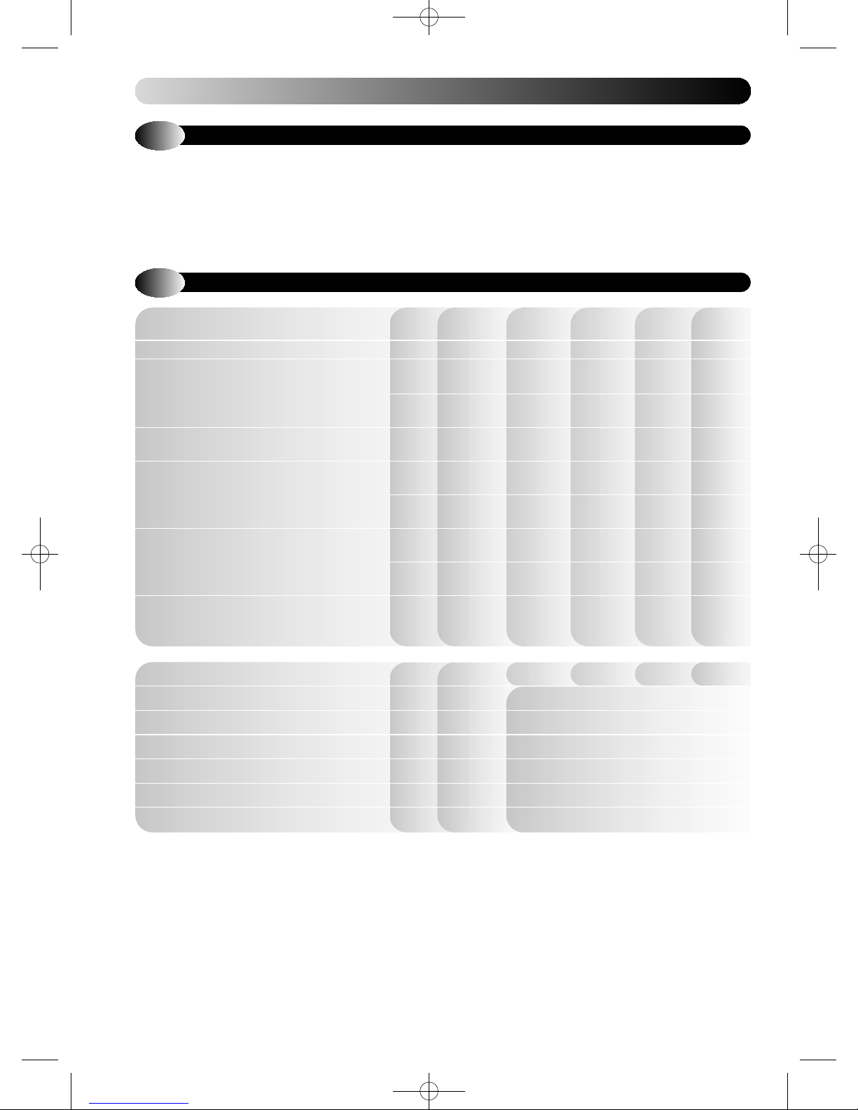
2.2
Appliance VBX30 VBX18 VBX30 VBX18
Mode Rate
Central Heating Output Max
(non-condensing)
(80 - 60 °C)
Central Heating Output
(condensing) (50 - 30 °C) (Btu/h) (109500) (65900) (109500) (65900)
Central Heating Input
Max Rate
Central Heating Input
Min Rate
Central Heating Gas Rate
(after 10 min operation - hot)
GAS CATEGORIES
(G20 with a governed gas supply at 20 mbar (8 in.wg) inlet
PERFORMANCE DATA
Min
Max
Net
Gross
Net
Gross
Max (ft3/h) (113.7) (68.9)
Eden VBX 30 Propane, Eden VBX 18 Propane:
(G31 (Propane) with a regulated gas supply at 37 mbar (14.9 in.wg)
II
2H3P
inlet pressure).
The appliance classification (as defined in EN 483) may be any of the
following depending on the chosen flue option: C
kW 30.0 18.0 30.0 30.0
(Btu/h) (102400) (61400) (102400) (61400)
kW 8.2 5.9 8.2 5.9
(Btu/h) (28200) (20100) (28000) (20100)
kW 32.1 19.3 32.1 19.3
kW 30.4 18.4 30.4 18.4
(Btu/h) (103700) (62800) (103700) (62800)
kW 33.8 20.4 33.0 20.0
(Btu/h) (115300) (69600) (112700) (68300)
kW 7.6 5.5 7.6 5.5
(Btu/h) (26000) (18800) (26000) (18800)
kW 8.4 6.1 8.3 6.0
(Btu/h) (28600) (20800) (28300) (20500)
m3/h 3.22 1.95
kg/h 2.36 1.43
, C33, C53, or B
13
Propane Propane
23
Seasonal Efficiency % 90.4 90.3 92.4 92.3
Seasonal Efficiency (SEDBUK) Band “A”
Nox Classification Class “5”
Min Central Heating System Pressure (Head) Bar 0.1 (1m H2O)
Max Central Heating System Pressure (Head) Bar 3.0
Max Central Heating Flow Temperature °C 80
Min Central Heating Flow Temperature °C 30
2
Page 5
SINGLE PAGES 20/9/10 09:59 Page 5
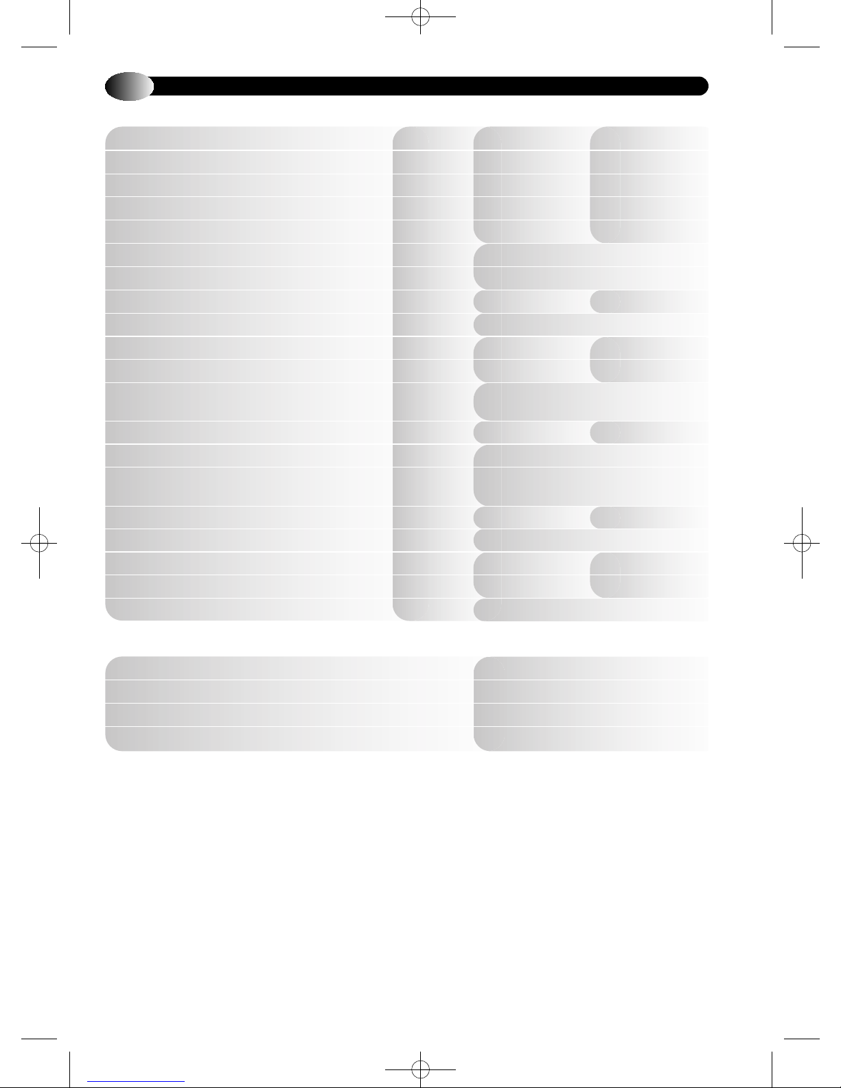
2.3
Natural Gas and Propane versions
Appliance VBX30 VBX18
Total weight (full) kg 38.1 32.6
Total weight (empty) kg 36.1 31.3
Max lift weight kg 28.1 24.7
Total water capacity l 2.0 1.3
Electrical supply 230V 50Hz Fuse at 3A
Internal fuse T4H 4A 250V
Maximum power consumption W 47 30
IP Rating IP20
Flue gas temperature Nat Gas 80/60 (Propane) °C 73 (76) 74 (72)
Flue gas temperature Nat Gas 50/30 °C 41 43
CO
CO2value min rate (Nat Gas) ref only % 8.9 ± 0.1 8.4 ± 0.1
CO value max rate (Nat Gas) % 0.01 ± 0.005
CO
CO2value min rate (Propane) ref only % 10.0 ± 0.1 9.7 ± 0.1
CO value max rate (Propane) % 0.019 ± 0.005
Flue products mass flow rate g/s 13.7 8.3
Flue products mass flow rate (Propane) g/s 13.7 8.3
Gas Valve Offset @ min rate Pa -3.0
GENERAL SPECIFICATIONS
value max rate (Nat Gas) %
2
value max rate (Propane) %
2
9.2 ± 0.3 case on
9.0 ± 0.2 case off
10.7 ± 0.3 case on
10.5 ± 0.2 case off
Connections
Gas 15mm compression
CH Flow 22mm tail
CH Return 22mm tail
Condensate Drain 21.5 - 22mm plastic overflow pipe
3
Page 6
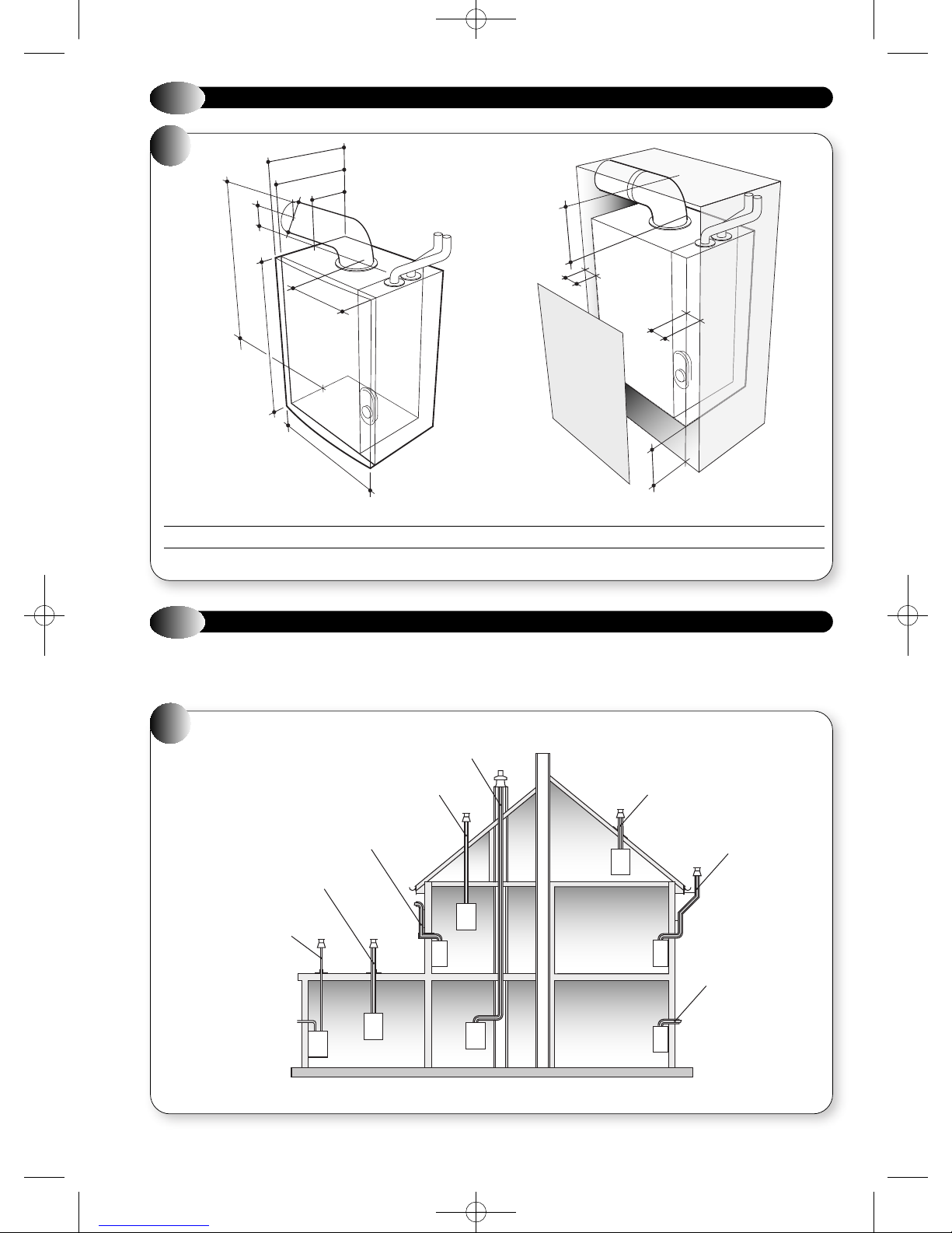
Vertical flue kit - Part no. 956081
with flat roof flashing plate
Vertical flue kit - Part no. 956081
Flue system application
Vertical flue kit - Part no. 956081
Split pipe vertical flue outlet kit
- Part no. 956080
with flat roof flashing plate
Raised external flue outlet kit
- Part no. 956084
Chimney flue liner kit
- Part no. 956082
External vertical flue kit
- Part no. 956085
Telescopic horizontal flue kit
- Part no. 956120
SINGLE PAGES 20/9/10 09:59 Page 6
2.4
1
EDEN VBX18 320 280 150 97 100 694 200 540 400 200 5 5 200
EDEN VBX30 360 320 150 97 100 694 200 540 400 200 5 5 200
OVERALL DIMENSIONS AND MINIMUM CLEARANCES
A
B
C
D
F
E
G
H
I
ABCDEFGHI JKLM
J
K
L
M
2.5
The EDEN 'x-type' range can be installed to a number of different
concentric flue systems. The different flue applications as shown
in Figure 2 are available as kits usually comprising the connecting parts
2
CONCENTRIC AIR / FLUE DUCT SPECIFICATIONS
FLUE OPTIONS
to the appliance and end terminal. Flue extension ducts and extension
elbows are available as accessories.
The following systems are available for the EDEN ‘x-type’ range.
4
Page 7
SINGLE PAGES 20/9/10 09:59 Page 7
2.5.1
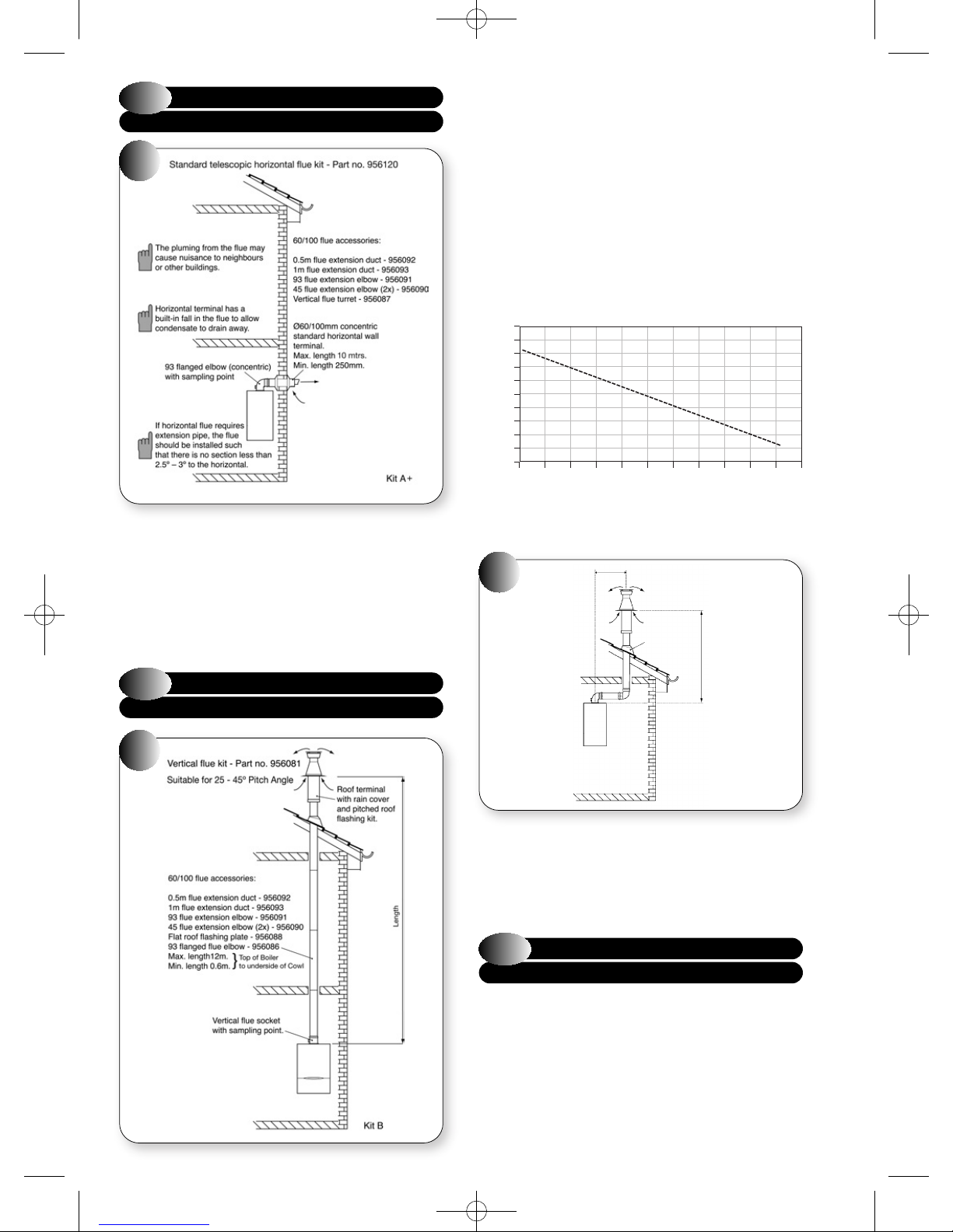
KIT A + TELESCOPIC HORIZONTAL WALL
TERMINAL (C13) - PART NO. 956120
3a
Traditional concentric flue system, Figure 3a, with a maximum length
of 10m*. The flanged flue elbow is designed with 3° slope towards the
appliance so that the condensate can easily drain off. It has to be
considered that for every metre horizontal flue length the terminal exit
centreline is approx. 45 mm higher than the elbow’s centreline. The
standard telescopic terminal is 615mm max length and 430mm min
length, but can be cut to a minimum flue length of 250mm, which is
suitable for single, 100mm (4"), brick walls.
Standard concentric (ø100/60) vertical flue application, Figures 3b, 3c,
through roof attics with a maximum length of 12m*. The kit comprises
of the roof terminal, vertical adaptor with sampling point and bracket.
The maximum length is measured from the top of the appliance casing
to the underside of the air cowl.
The maximum length is measured from the top of the appliance casing
to the underside of the air cowl.
For installation details refer to the flue kit instructions.
* Note: Flues which exceed 7mtrs in length will be subject to a small
percentage decrease in heat input (below the standard tolerance) as
shown in graph ‘A’ below.
GRAPH A
102.0
101.0
100.0
99.0
98.0
97.0
96.0
Heat input (%)
95.0
94.0
93.0
92.0
Horizontal flues (
Reduction in heat input as flue length increases
0123456789 1011
Flue Length (m)
C33) up to 10m in length, or equivalent, may be
used, however a reduction in the heat input will occur. The graph
shows details.
3c
a
Roof terminal
with rain
cover and
pitched roof
flashing kit.
b
2.5.2
3b
KIT B VERTICAL CONCENTRIC FLUE
TERMINAL (C33) - HBL PART 956081
Fig 3(c) Offset vertical flue.
‘a’ measured from boiler flue outlet centre line to the centre line of
the extension elbow.
‘b’ measured from the top of the boiler to the underside of the air cowl.
Maximum allowable length of a + b = 8900mm
2.5.3
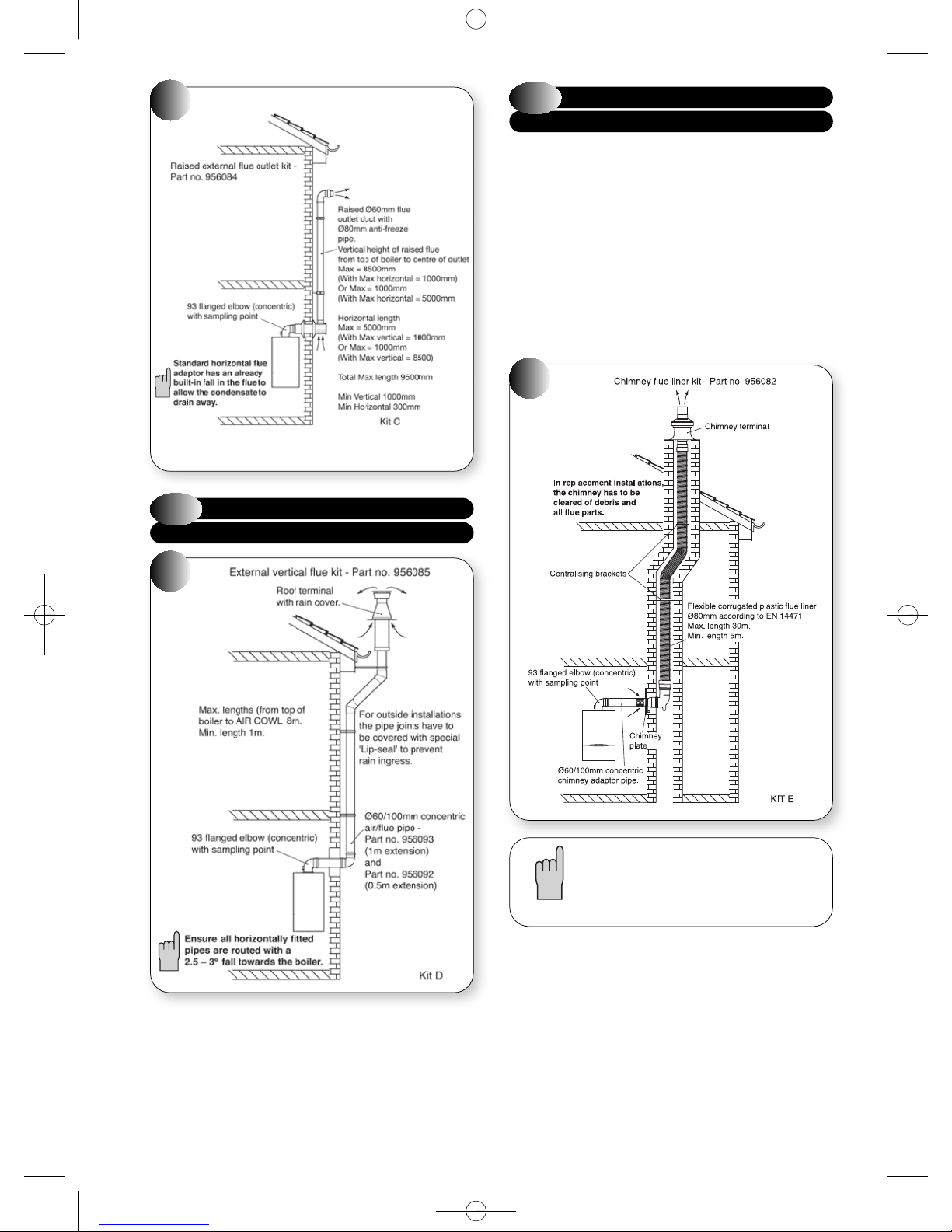
KIT C: HORIZONTAL ANTI-PLUME
FLUE KIT (C13) - PART NO. 956084
If the standard horizontal terminal is likely to cause nuisance to a
neighbour or buildings, because of excess pluming, then this particular
flue kit raises the flue gas outlet point to a higher elevation with the
minimum amount of changes. The flue gas duct is teed-off from the
concentric part and covered by an 80mm outer tube to protect the flue duct
from freezing. The air in-take remains at the lower level (see Figure 3d).
If choosing this option then the external flue duct length should be taken
into account when calculating equivalent flue length.
For installation details refer to the flue kit instructions.
5
Page 8
SINGLE PAGES 20/9/10 09:59 Page 8
3d
2.5.4
KIT D EXTERNAL VERTICAL FLUE - (C33)
PART NO. 956085
2.5.5
KIT E CHIMNEY FLUE LINER KIT
(B23) - PART NO. 956082
This kit is suitable for open flue application in accordance with BS5440
where a room sealed flue installation is impractical. The kit comprises of
a flue adaptor from the appliance to the chimney, a flexible plastic flue
liner with connection parts and chimney terminal (see Figure 3f). Where
an open flue system is used, then an air vent must be provided in the
same room or internal space as the flue duct air inlet, see section 3.4.
For installation details refer to the flue kit instructions.
Max flexi liner length = 30mtrs
Min flexi liner length = 5mtrs
Max concentric length = 2000mm
Min concentric length = 100mm
3f
3e
Suitable for installations if the appliance can’t be repositioned and
where other horizontal flue options may causes some nuisance to
neighbours or buildings. The flue kit contains some additional 45°
elbows and extension ducts as well as a special wall bracket to pass the
guttering (see Figure 3e). The concentric flue will be routed vertically
alongside the outside wall to above the roofline. Special seals are
required to prevent rainwater penetrating the pipe joints.
For installation details refer to the flue kit instructions.
6
A flue system can be built up from the components
detailed in the table on the next page, but the total
flue resistance must not exceed the maximum
stated.
Page 9
SINGLE PAGES 20/9/10 09:59 Page 9
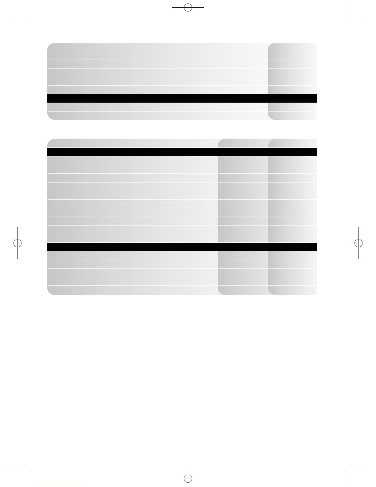
FLUE LENGTHS
Length supplied in standard kit - horizontal 815mm
Max horizontal length (from boiler to chimney - 60/100mm) 2000mm
Min horizontal length (from boiler to chimney - 60/100mm) 100mm
Max vertical length (from boiler to chimney - 60/100mm) 2000mm
Min vertical length (from boiler to chimney - 60/100mm) 200mm
Length supplied in standard kit - vertical (available in 10m, 20m and 30m length) N/A
FLEXITUBE MUST BE PURCHASED AS AN ACCESSORY TO COMPLETE THE KIT
Flexi tube min length 5m
Flexi tube max length 30m
(See below)
ACCESSORIES
Description Part No. Resistive Length
HORIZONTAL - 60/100 Accessories
Flue extension duct - 500mm 956092 450mm
Flue extension duct - 1000mm (Incl. 1 x support bracket) 956093 950mm
93° extension elbow 956091 1550mm
45° extension elbow (pair) 956090 775mm
Air inlet duct - included in kit N/A N/A
Straight adapter (60/80) - included in kit N/A N/A
91.5° adapter elbow (80/80) - included in kit N/A N/A
Support bracket - 100mm 840517 N/A
93° flanged elbow - included in kit 956082 N/A
Vertical turret socket 956087 N/A
VERTICAL - Accessories
Flexi tube - 10m 956110 10m
Flexi tube - 20m 956111 20m
Flexi tube - 30m 956112 30m
Straight duct (80) - included in kit N/A N/A
Chimney terminal - included in kit N/A N/A
NOTE: RESISTIVE LENGTH INFORMATION ONLY REQUIRED FOR COAXIAL FLUE PARTS. THE CORRUGATED (FLEXI TUBE)
FLUE PARTS ARE FIXED AND ALL PARTS ARE REQUIRED FOR EVERY APPLICATION.
7
Page 10
SINGLE PAGES 20/9/10 09:59 Page 10
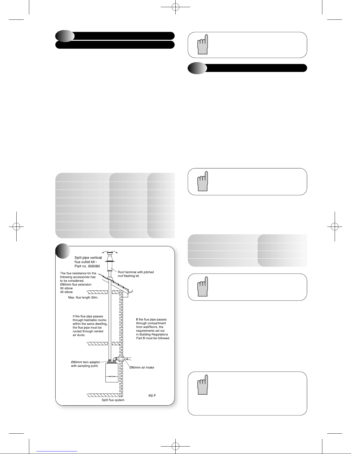
2.5.6
KIT F: TWIN FLUE SYSTEM (C53)
PART NO. 956080
This flue system kit is designed for installations where the air intake
position is different than the flue duct exit point. The kit comprises of a
twin adaptor from which the air intake is taken from the adjacent outside
wall (see example Figure 3g) and the flue duct is routed vertically
through the roof.
It has to be noted that the flue duct is under pressure when the appliance
is in operation and the duct can leak poisonous carbon monoxide if the duct
components are not correctly assembled. It is not recommended to route
the flue duct through living space areas, i.e. bed rooms, living rooms etc.
For installation details refer to the instructions provided with the twin
flued kit.
For C53 flue systems the terminal for the supply of combustion air and
for the evacuation of combustion products shall not be installed on
opposite walls of the building.
Maximum flue resistance permitted for a twin flued system
= 52 Pa
Minimum flue resistance permitted for a twin flued system
= 23.5 Pa
Flue Component Flue Resistance (Pa) Part Number
Twin Flue Adaptor (required) 9.5 Air Inlet Terminal (required) 3 Chimney Terminal (required) 0.5 80 mm dia straight duct 1 metre 1 956101
80 mm dia straight duct 2 metre 2 956102
90° Elbow (80/80) 8 956100
45° Elbow (80/80) 4 956099
3g
A flue system can be built up from the components
detailed in the table, but the total flue resistance
must not exceed the maximum stated.
2.6
The following additional concentric kits are available as optional extras.
Flue Extension Ducts - 1000 mm and 500 mm long, (each duct extends
the flue length by up to 950 mm and 450 mm respectively).
93° Extension Elbow - Allows an additional bend in the flue, and has an
'equivalent length' of 1550 mm. This elbow is mechanically different
from the flanged elbow supplied as standard with the appliance, but has
the same equivalent length.
45° Extension Elbow - Allows an additional bend in the flue and has an
'equivalent length' of 775 mm.
Vertical Turret Socket - For use with elevated horizontal flues and
vertical terminals.
Vertical Roof Terminal - For use where an external wall is not available,
or where it is desirable to route the ducts vertically.
These optional kits may be used with the standard flue kits to produce an
extensive range of flue options, providing that the following rules are
strictly obeyed.
a) The maximum/minimum permissible length of the room sealed flue
Horizontal flue terminal (all orientations) maximum 10000 mm (197 in)
Horizontal flue terminal (rear exit) minimum 250 mm (10 in)
Vertical flue terminal maximum 12000 mm (472 in)
Vertical flue terminal minimum 600 mm (23
ADDITIONAL CONCENTRIC FLUE KITS
For installation details refer to the instructions
provided with the individual flue kits.
system are:
1
/2in)
8
The 'equivalent' flue length must not exceed the
maximum values stated.
b) The standard terminal must always be fitted horizontally; horizontal
ducts must have a continuous fall towards the appliance of 2.5°. This
ensures condensate runs back into the appliance from the flue
system. The vertical terminal must always be used if a vertical
outlet is required.
c) The concentric flue system must use either a flanged elbow or a
vertical flue turret socket at the entry/exit to the appliance.
d) All joints must be correctly made and secured in accordance with
the installation instructions. When cutting ducts, avoid swarf,
uneven and sharp edges to maintain duct integrity.
Refer to Figures 2 and 3 to determine which option
kits are required before commencing the installation.
Instructions for installing the appliance with a
horizontal flue and straight extension ducts are
included in the main text of these instructions
(section 4.8).
Page 11
SINGLE PAGES 20/9/10 09:59 Page 11
2.6.1
PLUME DIVERTER
TERMINAL INSTALLATION
Plume Diverter Kit Part No: 956103
(For use with Standard horizontal flue kit - Part no 956083 - only)
This kit is provided to assist in fitting a condensing boiler with reduced
clearances when fitted in good practice according to the Guide to
Condensing Boiler Installation published by DEFRA/HMSO.
This kit allows the boiler flue outlet to be directed to the left or to the
right only.
INSTALLATION INSTRUCTIONS
Under certain operating conditions condensing appliances have a tendency
to form a plume of water vapour at the terminal. Therefore consideration
should be given when fitting the Plume Diverter in terms of plume
dispersal onto adjacent surfaces and neighbouring properties.
a) Refer to section 2.5 for instructions on fitting the flue system.
Also see Figure 5 for all other clearances.
3h
The resistance of the diverter is equivalent to 0.5
metre of flue length. Ensure this is used when
calculating the maximum allowable flue length.
(maximum horizontal flue length restricted to 9.5
metres when using the plume diverter).
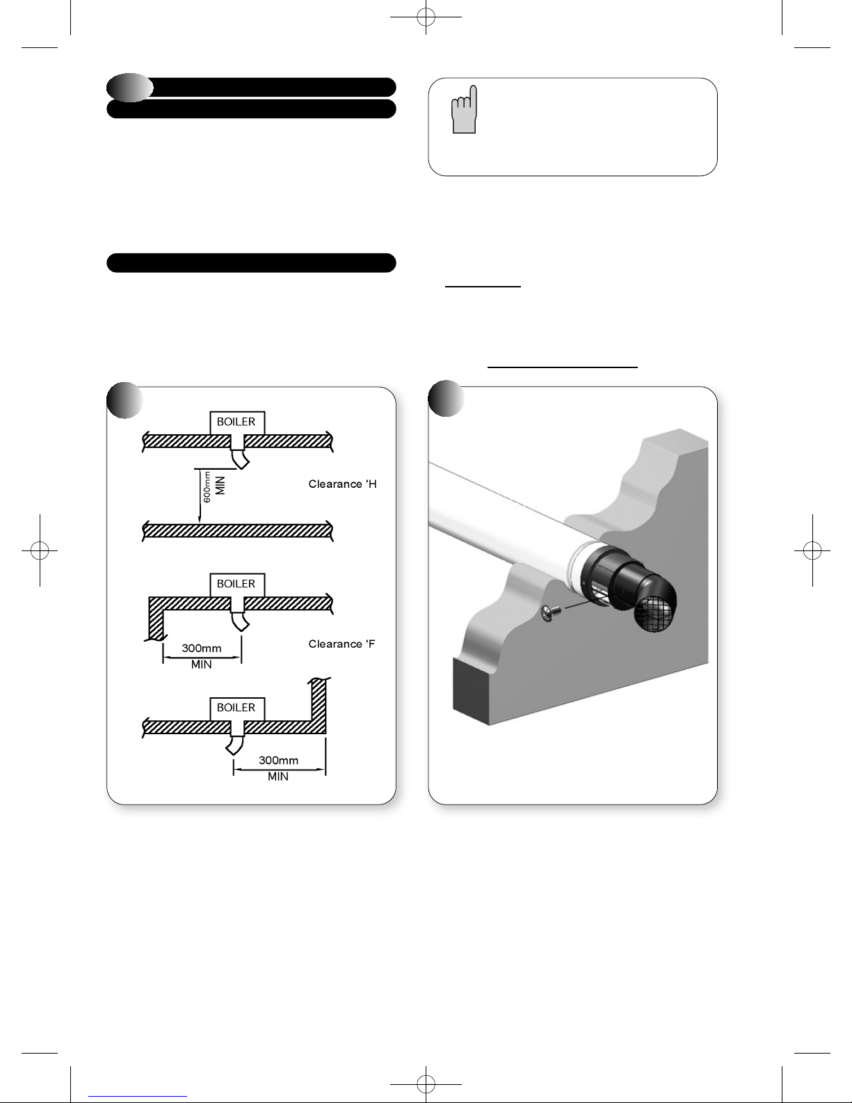
The diverter allows the terminal clearance to be reduced as follows (see
diagrams below):
Clearance H – From a surface facing the terminal - 600mm.
Clearance F – From internal or external clearances - 300mm.
b) Choose the direction required to deflect the flue products
(left or right only)
c) Push the diverter elbow onto the angled outlet of the flue terminal
in the desired rotational position and ensure the diverter is pushed
up to the shoulder to fully engage the rubber seal.
d) Fix the diverter to the flue terminal with the self drilling screw
provided. Do not use a power tool to fit screw.
3i
Note.
The Plume Diverter terminal must not under any
circumstances deflect flue products downwards.
9
Page 12
SINGLE PAGES 20/9/10 09:59 Page 12
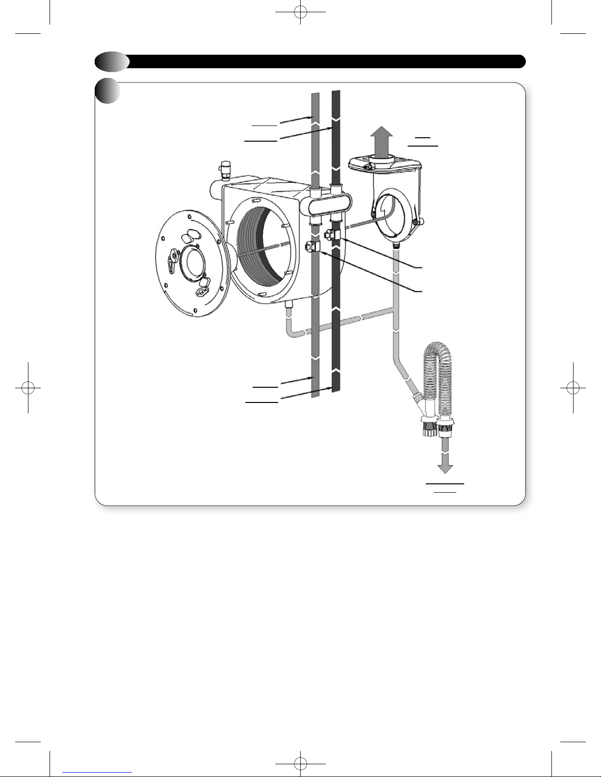
2.7
4
APPLIANCE HYDRAULIC CIRCUITS
CH RETURN
BURNER &
BURNER
FLANGE
CH FLOW
PRIMARY HEAT
EXCHANGER
FLUE
PRODUCTS
CH RETURN
THERMISTOR
CH FLOW
THERMISTOR
CH FLOW
CH RETURN
CONDENSATE
TRAP
CONDENSATE
OUTLET
10
Page 13
SINGLE PAGES 20/9/10 09:59 Page 13
3
INSTALLATION REQUIREMENTS
3.1
GAS SAFETY (INSTALLATION AND USE) REGULATIONS 1996 (AS
AMENDED)
The appliance is suitable only for installation in GB and IE and should
be installed in accordance with the rules in force.
In GB, a CORGI Registered Installer must carry out the installation. It
must be carried out in accordance with the relevant requirements
of the:
Gas Safety (Installation and Use) Regulations
The appropriate Building Regulations either The Building Regulations,
The Building Regulations (Scotland), Building Regulations (Northern
Ireland).
The Water Fitting Regulations or Water Byelaws in Scotland.
The Current I.E.E Wiring Regulations.
Where no specific instructions are given, reference should be made to
the relevant British Standard code of Practice.
In IE, the installation must be carried out by a Competent Person and
installed in accordance with the current edition of I.S.813 “Domestic
Gas Installations”, the current Building Regulations and reference
should be made to the current ETCI rules for electrical installation.
It should also be in accordance with the relevant recommendations in
the current editions of the following British Standards and Codes of
Practice: BS 5449, BS 5546, BS 5440-1, BS 5440-2, BS 6798, BS 6891,
Institute of Gas Engineer document IGE/UP-7, BS 7074 (expansion
vessel), BS 5482 (propane installations) and IS813 for IE.
IMPORTANT NOTE: Manufacturer's instruction must NOT be taken in
any way as overriding statutory obligations.
3.2
THE FOLLOWING LIMITATIONS MUST BE OBSERVED WHEN SITING
THE APPLIANCE:
a) The appliance is not suitable for external installations. The position
b) This position MUST allow for a suitable flue system and terminal
c) If the appliance is to be fitted in a timber framed building it should
d) The appliance is approved to a protection rating of IP20. Therefore
STATUTORY REQUIREMENTS
APPLIANCE LOCATION
selected for installation should be within the building, unless
otherwise protected by a suitable enclosure and MUST allow
adequate space for installation, servicing and operation of the
appliance and for air circulation around it (Section 2.4 and 3.4).
position. The appliance must be installed on a flat vertical wall,
which is capable of supporting the weight of the appliance and any
ancillary equipment.
be fitted in accordance with the British Gas publication 'Guide for
Gas Installations In Timber Frame Housing', Institute of Gas
Engineers document IGE/UP-7. If in doubt, advice must be sought
from the Local Gas Supplier.
if the appliance is to be installed in a room containing a bath or a
shower, any electrical switch or control utilising mains electricity
must be so situated that it cannot be touched by a person using the
bath or shower. Attention is drawn to the requirements of the
current BS 7671 (I.E.E Wiring Regulations) and in Scotland the
electrical provisions of the Building Regulations applicable in
Scotland.
3.3
DETAILED RECOMMENDATIONS FOR FLUE INSTALLATION ARE
GIVEN IN BS 5440-1. THE FOLLOWING NOTES ARE FOR GENERAL
GUIDANCE.
a) The appliance MUST be installed so that the terminal is exposed to
b) It is important that the position of the terminal allows free passage
c) It is ESSENTIAL TO ENSURE that products of combustion
d) The minimum acceptable dimensions from the terminal to
e) If the terminal discharges into a pathway or passageway check that
f) Where the lowest part of the terminal is fitted less than 2000 mm (78
g) The air inlet / flue outlet MUST NOT be closer than 25 mm (1 in) to
h) Condensing appliances have a tendency to form a plume of water
3.4
Detailed recommendations for air supply are given in BS 5440-2.
The following notes are for general guidance.
a) It is not necessary to have a purpose provided air vent in the room
b) Cupboard or compartment ventilation is not necessary for a room-
c) Where an open flued, (B23), system is used, then an air vent must be
d) If the appliance is installed in a room or internal space with other
FLUE TERMINAL POSITION
the external air.
of air across it at all times.
discharging from the terminal cannot re-enter the building or any
other adjacent building, through ventilators, windows, doors, other
sources of natural air infiltration, or forced ventilation / air
conditioning.
obstructions and ventilation openings are specified in Figure 6.
combustion products will not cause nuisance and that the terminal
will not obstruct the passageway.
in) above the ground, above a balcony or above a flat roof to which
people have access, the terminal MUST be protected by a purpose
designed K6 terminal guard (optional extra: Part No. 951507).
combustible material.
vapour at the terminal under certain operating conditions. This is
normal but positions where this would cause damage or a nuisance
should be avoided. Consideration should be given to the dispersal of
the plume in terms of adjacent surfaces and neighbouring
properties. A special flue terminal, (Kit C), is available to raise the
flue discharge point; use of this terminal will limit the maximum
flue length available.
For further information contact: Halstead Glen Dimplex service
helpline Tel: 0844 371 1111.
VENTILATION REQUIREMENTS
or internal space in which a room-sealed appliance is installed.
sealed appliance providing that the minimum clearances are
maintained.
provided in the same room or internal space as the flue duct air
inlet, with a minimum free-area of at least:
VBX 30 117 cm
VBX 18 57 cm
opened flued appliances, then the size of the air vent necessary
should be calculated in accordance with BS 5440-2 Table 2.
2
2
11
Page 14
SINGLE PAGES 20/9/10 09:59 Page 14
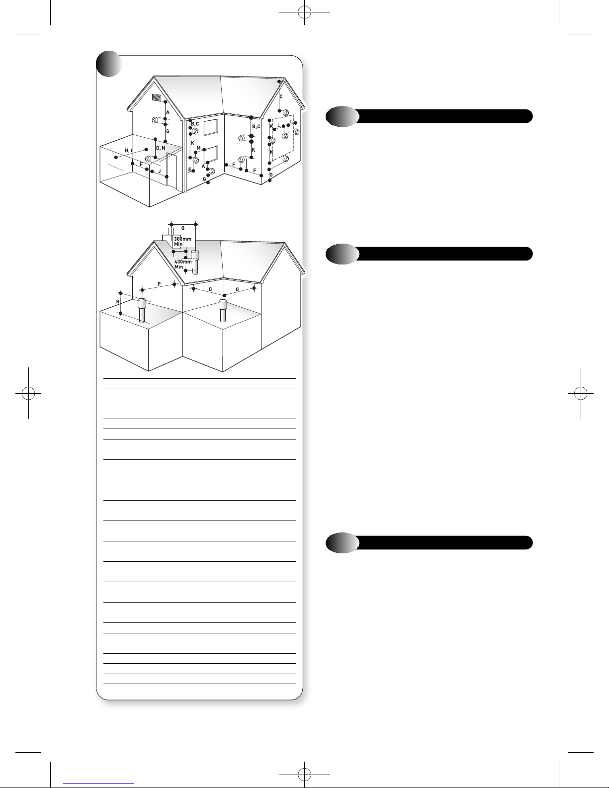
FLUE TERMINAL POSITION
5
SPECIAL REQUIREMENTS FOR A
VERTICALLY BALANCED FLUE
Position Minimum spacing
A Directly below an openable window, 300mm 12in
air vent, or any other ventilation
opening
B Below gutter, drain/soil pipe 75mm 3in
C Below eaves 200mm 8in
D Below a balcony 200mm 8in
*2500mm 98in
E From vertical drain pipes and 150mm 6in
soil pipes
F From internal or external corners 300mm 12in
*internal corners *1000mm 40in
G Above adjacent ground or
balcony level 300mm 12in
H From a surface facing the terminal 600mm 24in
*2500mm 98in
I Facing terminals 1200mm 48in
*2500mm 98in
J From opening (door/window) in 1200mm 48in
carport into dwelling *not recommended
K Vertically from a terminal on the 1500mm 60in
same wall
L Horizontally from a terminal on the 300mm 12in
same wall
M Adjacent to opening 300mm 12in
N Below carport 600mm 24in
*not recommended
O From adjacent wall 300mm 12in
P From adjacent opening window 1000mm 40in
Q From another terminal 600mm 24in
R Minimum height 300mm 12in
e) Where an open flued system is used, and the flue duct air inlet is
within a compartment then high and low level air vents are
necessary in the compartment, the size of the vents should be
calculated in accordance with BS 5440-2 Table 2.
3.5
The condensate drain connection is suitable for either 21.5 mm or 22
mm plastic push fit or adhesive overflow pipes and fittings. It should
be piped to drain, preferably within the building, maintaining a
continuous 2.5° fall away from the appliance. If the drain is routed to
outside it should be to a drain or soak away, and any external pipe
work should be in 32 mm. Insulation to protect from freezing in cold
weather conditions is also advisable. Note if the appliance is installed
in a garage all pipe work should be in 32 mm. Ensure that the
condensate discharge system complies with any local regulations in
force.
3.6
a) The Gas Supplier should be consulted at the installation planning
b) An existing service pipe MUST NOT be used without prior
c) A gas meter can only be connected by the Gas Supplier or by
d) An existing meter and/or pipe work should be of sufficient size
A minimum of 22 mm diameter pipe work is recommended within
1000 mm of the appliance gas cock.
e) Natural gas appliances: The governor at the meter must give a
f) The gas supply line should be purged. WARNING: Before purging
g) The complete installation must be tested for gas tightness.
3.7
a) The appliances incorporate all the components necessary to allow
b) The installation should be designed to operate with a flow
c) A sealed system must only be filled by a competent person.
d) The available pump head for the appliances are given in
e) If thermostatic radiator valves are fitted, a radiator must be fitted
CONDENSATE DISPOSAL
GAS SUPPLY
stage in order to establish the availability of an adequate supply
of gas.
consultation with the Gas Supplier.
their contractor.
to carry the maximum appliance input plus the demand of any
other installed appliance. (BS 6891: 1988).
constant outlet pressure of 20 mbar (8 in.wg) when all appliances
on the system are running.
Propane appliances: The regulator must give a constant outlet
pressure of 37 mbar (14.9 in.wg) when all appliances on the
system are running.
open all doors and windows, also extinguish any cigarettes,
pipes, and any other naked lights.
CENTRAL HEATING SYSTEM
them to be connected to a sealed central heating system. Refer to
Figure 7a for a typical system design, which incorporates
radiators, and a drain facility that must be provided at the lowest
point in the system to allow complete drain down.
temperature of up to 95 °C.
Figure 6.
with two lock shield valves, to enable correct operation of the
pump-overrun facility.
*Recommended by the boiler manufacturing industry to prevent pluming
12
nuisance and damage to buildings.
Page 15
Pressure Drop (m H
O)
SINGLE PAGES 20/9/10 09:59 Page 15
f) The following paragraphs outline the specifications of the items
fitted to the appliances.
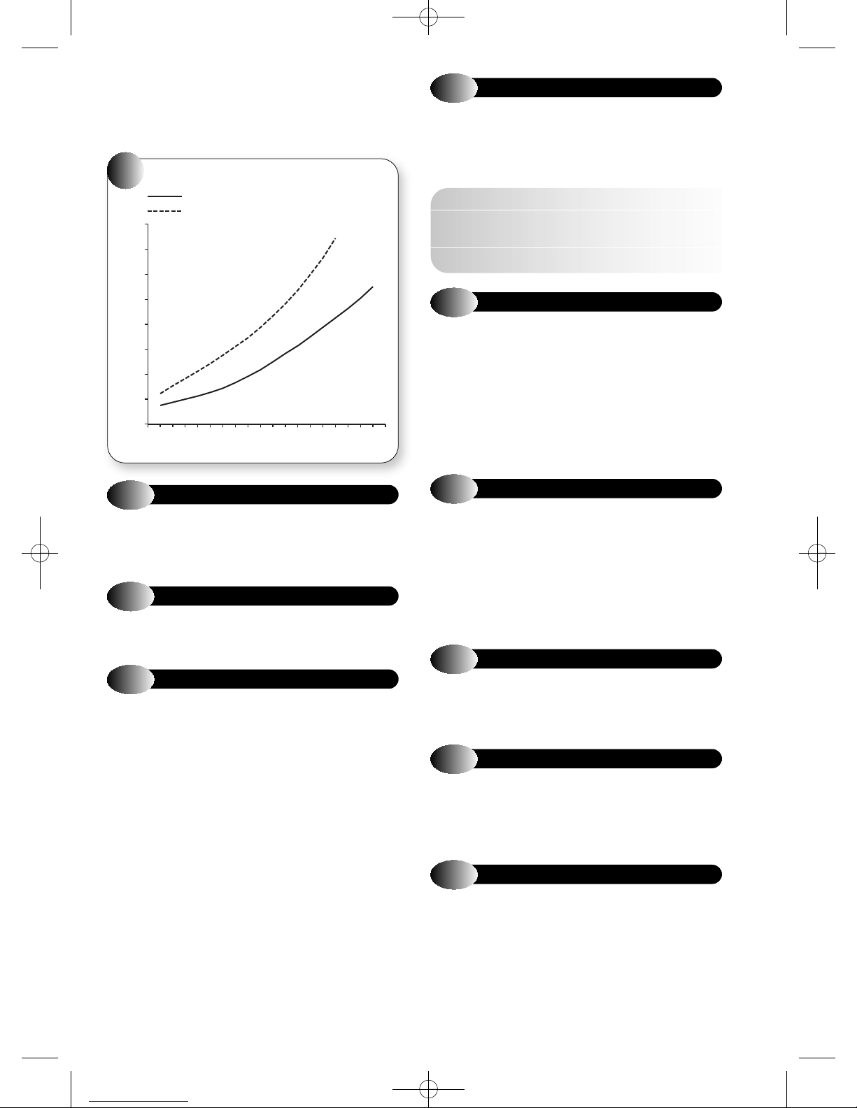
PUMP - The available pump head shown in Figure 6 is that in excess of
the appliance hydraulic resistance, i.e. that available for the system.
APPLIANCE HYDRAULIC RESISTANCE
6
VBX 30
4
3.5
3
2
2.5
2
1.5
1
0.5
0
VBX 18
5 6 7 8 9 10 11 12 13 14 15 16 17 18 19 20 21 22 23
Flow Rate ltr/min
24
3.11
If it is necessary to alter the flow rate, the system can be fitted with a
lockable balancing valve in the main flow or return pipes shown as valve
“A” in figure 7. The flow rate through the boiler must not be allowed to
fall below that given in table 1.
3.12
WATER TREATMENT, CLEANSING AND FLUSHING THE HEATING
SYSTEM
NOTE: British Standard BS7593: 1992 stresses the importance of
cleansing and flushing of the system to ensure it continues to run
efficiently with the minimum of maintenance necessary. Halstead
Boilers fully support this professional approach and recommend that
the system is cleansed with an effective chemical cleanser and
protected long term with a suitable inhibitor. Such products are available
from Fernox and Sentinal.
FLOW RATE
Table 1. Flow Rate
MINIMUM FLOW RATE
200 l/h
This is equal to 20°C differential at minimum heat input.
WATER TREATMENT
3.8
A draining tap must be provided at the lowest point of the system, which
will allow the entire system and hot water system to be drained.
Draining taps shall be to the current issue of BS 2879.
3.9
A safety valve need not be fitted to an open vented system. (See 3.16 for
sealed systems)
3.10
The pump should be fitted on the flow pipe from the boiler and have
isolating valves each side.
A variable duty pump should be set to give a temperature difference of
no greater than 20°C between the flow and return, with the thermostat
set at “MAX”, which is approximately 80° to give a flow rate as shown in
table 1.
See figure 6 for pressure loss of the boiler.
High resistance microbore systems may require a higher duty pump.
DRAINING TAP
SAFETY VALVE OPEN VENTED SYSTEM
PUMP
3.13
The boiler must be supplied from an unrestricted water supply taken
from a feed and expansion cistern situated at a maximum height of 27
metres (90ft) above the boiler.
The cold feed must be 15mm minimum size.
The vent must rise continuously and be unrestricted.
It is important that the relative positions of the pump, cold feed and open
vent are as shown in figure 8.
3.14
SINGLE FEED INDIRECT CYLINDERS ARE NOT SUITABLE
The domestic hot water cylinder must be of the double feed fully indirect
coil type.
3.15
The installation must comply with the appropriate requirements of the
current issue of BS4814, BS5449, BS6759, BS6798 and BS7074 Part 1
and 2.
See figure 7 for a suggested layout.
3.16
OPEN VENTED HOT WATER SYSTEM
DOMESTIC HOT WATER CYLINDER
SEALED HOT WATER SYSTEMS
SAFETY VALVE SEALED SYSTEM
A safety valve must be fitted to a sealed system.
It shall be preset, non-adjustable with a lift pressure of 3 bar,
incorporating seating of a resilient material, a test device and a
connection for drain.
The drain from the safety valve must be routed outside the building,
must not discharge above an entrance or window or any type of public
access area, be clear of any electrical fittings and positioned so that any
discharge can be seen.
13
Page 16
SINGLE PAGES 20/9/10 09:59 Page 16
3.17
EXPANSION VESSEL
A diaphragm type expansion vessel, conforming to the current issue of
BS4814 (see also BS7074 Part 1 and 2) must be connected at a point
close to the inlet side of the circulating pump, see the diagrammatic
layout, figure 7 unless laid down differently by the manufacturer.
The expansion vessel volume depends on the total water system volume
and the initial system design pressure. For any system an accurate
calculation of vessel size is given in the current issue of BS5449 and
BS7074 Part 1.
Example: For an initial design pressure of 0.7 bar, the minimum total
vessel volume required is 0.063 x Total System Volume.
Expansion Vessel Requirements
Vessel charge and initial
system pressure
bar 0.5 0.75 1.0 1.5
Total water content for
system using 8L (1.54 gal)
capacity expansion vessel
L 96 84 73 50
supplied with appliance
For systems having a
larger capacity, multiply
the total system capacity in
litres (gallons) by these
0.0833 0.093 0.109 0.156
factors to obtain the total
minimum expansion vessel
capacity required in litres.
Note: A higher initial design pressure requires a larger volume
expansion vessel.
The charge pressure must not be less than the static head of the system,
that is, the height of the highest point of the system above the expansion
vessel.
The water content of the boiler is given in 2.3 General Specifications.
3.18
PRESSURE GAUGE
A pressure gauge with a set pointer and covering at least 0 to 4 bar (0 to
60 lb/in) shall be fitted permanently to the system in a position where it
can be seen when filling the system.
3.19
WATER MAKEUP
Provision should be made for replacing water loss from the system
using a make up bottle mounted in a position higher than the top point
of the system, connected through a non-return valve to the return side
of either the heating circuit or the hot water cylinder.
Alternatively, provision for make up can be made using a filling loop.
3.20
FILLING A SEALED WATER SYSTEM
Provision for filling the system at low level must be made, see figure 8.
There must be no permanent connection to the mains water supply, even
through a non-return valve.
CONTROLS. As a minimum it is recommended that a room thermostat
be installed to control the appliance. Thermostatic radiator valves may
be fitted to the system, however they must not be fitted in the room
where the room thermostat is fitted. There must be at least one radiator
installed with lock shield valves that should not be closed. Further
guidance can be obtained from the Domestic Heating and Hot Water
Guide to the building regulations.
14
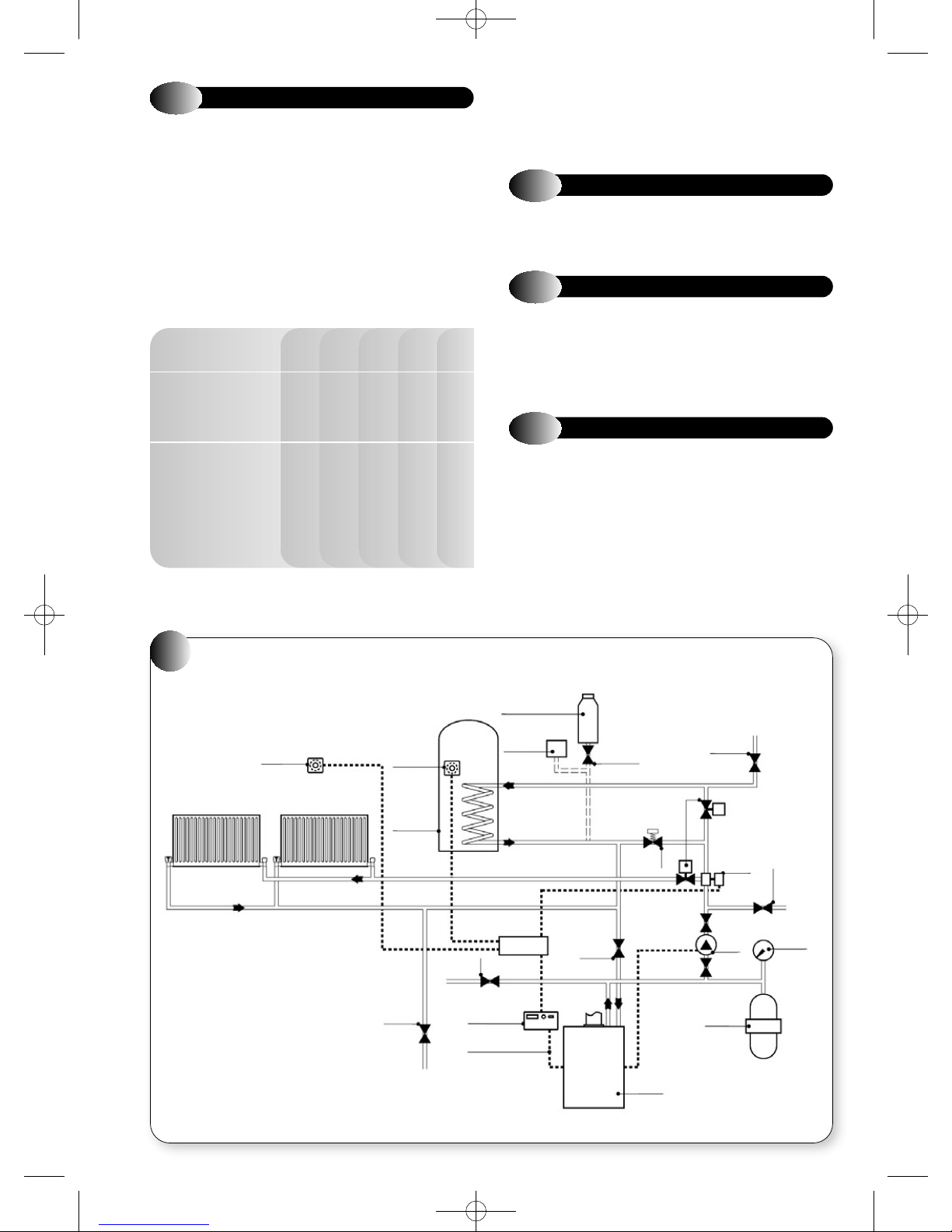
7
SEALED WATER SYSTEM
ROOM THERMOSTAT
FLOW
RETURN
NOTE: No automatic by-pass required. However,
it is recommended to leave one radiator open and
to fit a system by-pass in the DHW circuit to ensure
pump over-run functionality.
TANK
THERMOSTAT
HOT
WATER
CYLINDER
DRAIN
COCK
MAKE UP BOTTLE
Observe minimum
static head requirements
SAFETY
VALV E
CH/DHW
2 CHANNEL
PROGRAMMER
CH/DHW
SWITCHED LIVE
AUTOMATIC
AIR VENT
TERMINAL
BLOCK
LOCKABLE
BALANCING
VALVE “A”
NON RETURN
VALV E
SYSTEM
BYPASS
APPLIANCE
MOTORISED
VALV E
AIR RELEASE
VALV E
3-WAY
VALV E
PUMP
EXPANSION
VESSEL
FILL POINT
NON-RETURN
VALV E
PRESSURE
GAUGE
Page 17
SINGLE PAGES 20/9/10 09:59 Page 17
3.21
ELECTRICITY SUPPLY
a) Wiring external to the appliance must be in accordance with the
current I.E.E Wiring regulations (BS 7671) for electrical installation
and any local regulations, which apply.
b) The mains cable must be at least 0.75 mm2 (24/0.2 mm) PVC
insulated to BS 6500 table 16.
c) THIS APPLIANCE MUST BE EARTHED. Failure to provide a
satisfactory earth connection will result in appliance malfunction.
8
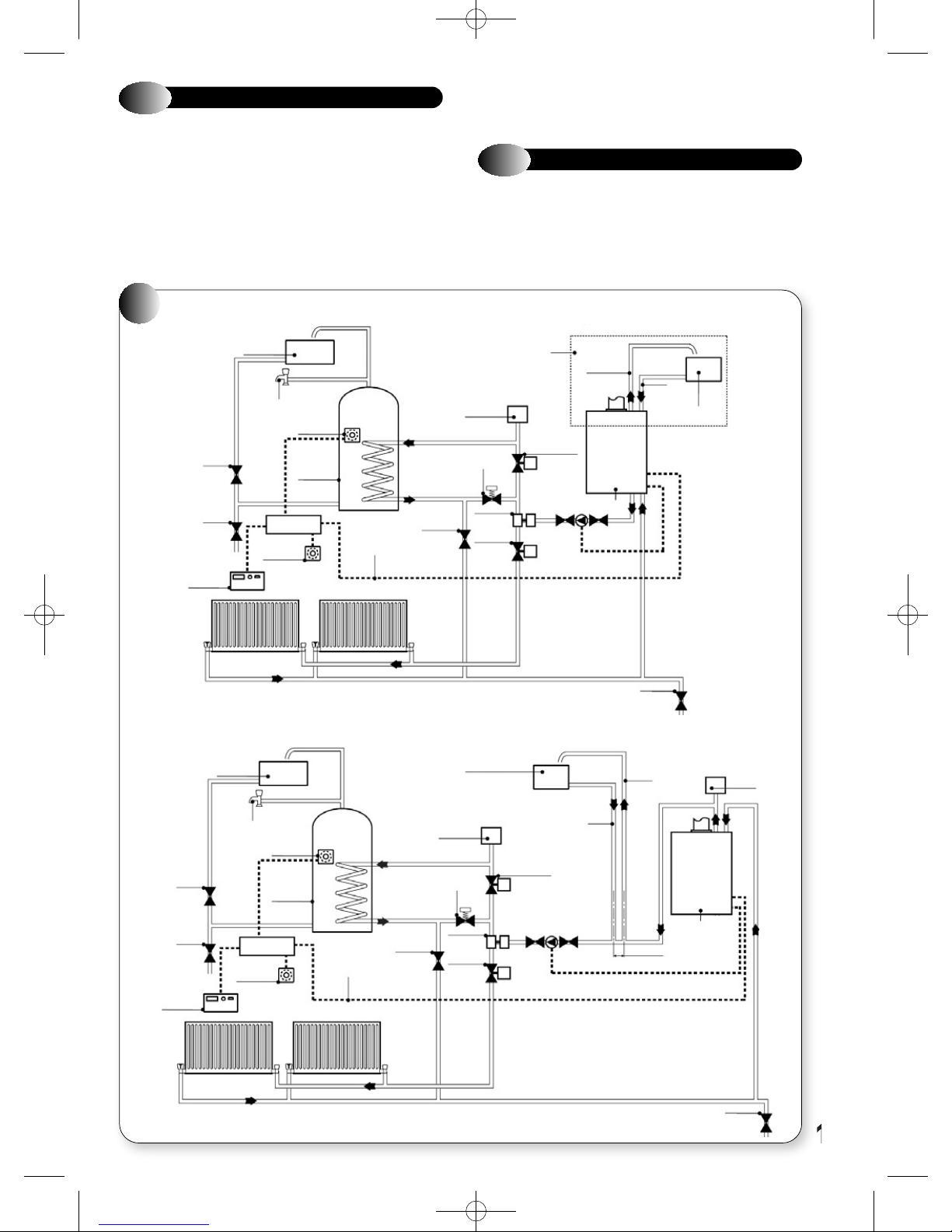
OPEN VENT WATER SYSTEM with flow and return connected to bottom pipes
COLD WATER
STORAGE
TO DRAIN
OFF TAP
TANK
THERMOSTAT
STOP
VALV E
DRAIN
CH/DHW
2 CHANNEL
PROGRAMMER
TERMINAL
BLOCK
ROOM
THERMOSTAT
HOT WATER
CYLINDER
SWITCHED
LIVE
LOCKSHIELD
VALV E
SYSTEM
BYPASS
NOTE:- Flow
and return
pipes must be
run in copper
for a minimum
of 1.5mtrs
RETURN
FLOW
from the boiler.
OPEN VENT WATER SYSTEM with flow and return connected to top pipes
The VBX appliances may be used with any certified programmer/room
thermostat, as described in section 4. For further information contact:
Halstead Glen Dimplex service helpline Tel: 0844 371 1111.
3.22
EXTERNAL CONTROLS
d) The method of connection to the mains supply must facilitate
complete electrical isolation of the appliance. Either a 3A fused
three pin plug and un-switched shuttered socket outlet, both
complying with BS 1363, or a 3A fused double pole switch having a
3 mm contact separation in both poles and serving only the boiler
(and its external controls) may be used.
RECOMMENDATION ONLY
NOTE: PUMP REQUIRES
OPTIMISATION TO
PREVENT PUMP OVER
INTO FEED & EXPANSION
TANK
AUTOMATIC
AIR VENT
MOTORISED
VALV E
3-WAY
VALV E
MOTORISED
VALV E
EXPANSION
APPLIANCE
COLD
FEED
CH FEED &
EXPANSION TANK
NOTE: No automatic by-pass
required. However, it is
recommended to leave one
radiator open and to fit a
system by-pass in the DHW
circuit to ensure
DRAIN
pump over-run
functionality.
STOP
VALV E
DRAIN
CH/DHW
2 CHANNEL
PROGRAMMER
COLD WATER
STORAGE
TO DRAIN
OFF TAP
THERMOSTAT
RETURN
THERMOSTAT
HOT WATER
CYLINDER
TERMINAL
BLOCK
ROOM
TANK
SWITCHED
LIVE
FLOW
LOCKSHIELD
VALV E
AUTOMATIC
AIR VENT
SYSTEM
BYPASS
3-WAY
VALV E
MOTORISED
CH FEED &
EXPANSION TANK
VALV E
MOTORISED
VALV E
COLD
FEED
EXPANSION
150mm MAX
APPLIANCE
AUTOMATIC
AIR VENT
DRAIN
15
Page 18
SINGLE PAGES 20/9/10 09:59 Page 18
4
APPLIANCE INSTALLATION
Before installing the appliance, check that the chosen location is
suitable (section 3.2) and that the requirements for flue position (section
3.3) and minimum clearances (Figure 1b) are satisfied.
4.1
The appliance is supplied in one box. Flue kits are provided separately,
the various flue kits available as described in sections 2.5 - 2.7. If the
appliance is to be installed without access to an external wall, a wall
liner kit is also required.
Unpack the boxes and check the contents:
G
G
G
G
G
G
G
UNPACKING THE APPLIANCE
Complete appliance
Paper wall mounting template
Wall mounting plate
Installation and Servicing Instruction
User's Instructions
Warranty Card
Hardware pack containing:
50mm x No 10 Wood Screws - 4 off
Rawl Plug to suit - 4 off
Manual Handling Note:
During the appliance installation it will be necessary
to employ caution and assistance whilst lifting, as the
appliance exceeds the recommended weight for a
one-man lift. Take care to avoid trip hazards, slippery
or wet surfaces.
4.2
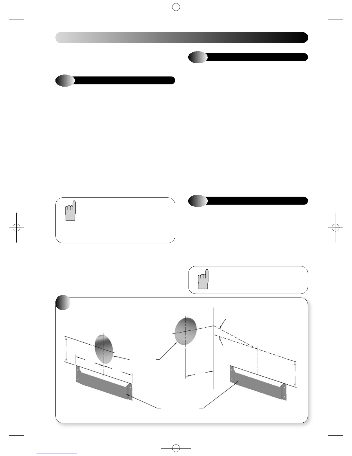
a) Fix the paper template in the required position (ensuring that the
b) Mark the position of the wall mounting plate-fixing holes (4). Select
c) Mark the position of the flue outlet. For side flue installation extend
d) Cut the hole in the wall for the air/flue duct (preferably with a core-
e) Drill the four fixing holes using a 6mm drill and insert the wall plugs
f) Hang the wall mounting plate using two fixing screws in the top,
4.3
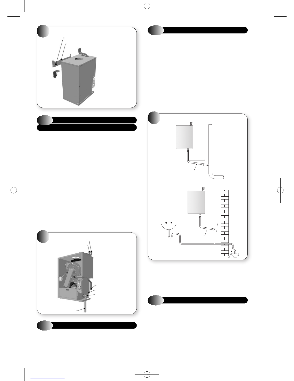
Refer to Figure 10.
a) Lift the appliance into position approximately 10 mm above the top
b) Connect the central heating system pipes to the central heating flow
PREPARING THE WALL
necessary clearances are achieved). Ensure squareness by hanging
a plumb line.
one from each group. Refer to Figure 10.
the flue centre line on to the sidewall, where the flue length exceeds
775 mm, a flue slope angle of 2.5° needs to be taken into account.
Refer to Figure 10. Remove the paper template.
boring tool). The hole must be horizontal and not be less than 100
mm in diameter. If the hole is not accessible from outside, its
minimum diameter must be sufficient to allow insertion of the wall
liner (130 mm, 5in). The wall liner is available as an optional extra
and must be sealed in position with mortar (or equivalent).
provided.
ensuring that it is level.
MOUNTING THE APPLIANCE
of the wall mounting plate and use the side wings on the plate to
locate the appliance in a horizontal direction. Then carefully lower
the appliance, ensuring that the top locating rail is securely
engaged.
and return pipes on the boiler.
16
9
108
190
Pipe work may be routed from above or below the
appliance as required.
2.5º
REAR FLUE SIDE FLUE
POSITION OF
DUCT HOLE
190
POSITION OF WALL
MOUNTING PLATE
127.5
101.5
Page 19
SINGLE PAGES 20/9/10 10:00 Page 19
MOUNTING THE APPLIANCE
10
WALL MOUNTING PLATE
RAIL LOCATION EDGE
CENTRAL HEATING SERVICE
4.4
CONNECTIONS
Refer to Figure 11.
a) The boiler is supplied with 22mm copper tails for both upwards and
downwards (optional) flow and return pipe routing suitable for
compression or soldering connections.
USE EXTREME CARE IF SOLDERING THE JOINTS NEAR TO THE
APPLIANCE. IF BOILER IS LOCATED IN TIGHT SPACE IT IS
RECOMMENDED TO REMOVE THE PIPES FROM THE BOILER.
b) Connect the central heating system pipes to the central heating flow
and return pipes on the boiler. If downwards routing is required:
The sealed ends must be removed before connecting to the heating
system pipes. The upwards pipes must be used for connecting to a
vent pipe (open system) or fitting to an automatic air vent (sealed
system). The remaining pipe must be solder sealed.
The flow and return sensors have to be removed from the upwards
pipes and reconnected to the downward pipes (Fig 47; flow is
nearest to the front).
c) Commission the central heating system as described in section 5.1,
and then proceed to section 4.5.
SERVICE CONNECTIONS
11
CH FLOW
CH RETURN
4.6
Refer to Figure 12.
Connect either a Ø21.5mm or Ø22mm plastic push fit or adhesive
overflow pipe to the condensate outlet. It should be piped to drain,
preferably within the building, maintaining a continuous 2.5° fall away
from the appliance. Note; if an additional “U” trap is fitted between the
appliance and the discharge point, then a visible air break is necessary
between the appliance and trap, because a trap is already provided
within the appliance. Ø32mm pipe should be used for external pipe
work, or if the appliance is installed in a garage. If the drain is routed
externally to a drain or soak away, then the external length should be
kept as short as possible and not exceed 3000 mm. Protection from
freezing in cold weather conditions is also advisable. Ensure that the
condensate discharge system complies with any local regulations in
force.
12
CONDENSATE CONNECTION
CONDENSATE CONNECTIONS
WASTE STACK
2.5º
CONDENSATE DRAIN
MUST BE
≥ Ø22
CONDENSATE
DRAIN
MUST BE ≥ Ø22
SINK WASTE
2.5º
CH FLOW (OPTIONAL)
CH RETURN (OPTIONAL)
MAINS GAS INLET
CONDENSATE OUTLET
4.5
Refer to Figure 11.
Connect the gas supply pipe to the gas service cock. It is recommended
that a minimum of 22 mm diameter OD copper pipe be used to within
1000 mm of the gas service cock.
GAS CONNECTION
EXTERNAL PIPE MUST BE ≥ Ø32mm
In exceptional circumstances, such as when a boiler is installed in a
basement without drainage, it may be necessary to install a condensate
pump to carry condensate up to ground/drain level. Such products are
available from Grundfos Pumps Ltd on: 01525 850000 and Pump House
on: 0115 922 2211.
4.7
For correct flue installation please refer to the installation instructions
that are provided with the individual flue kit as described in sections
2.5 - 2.7.
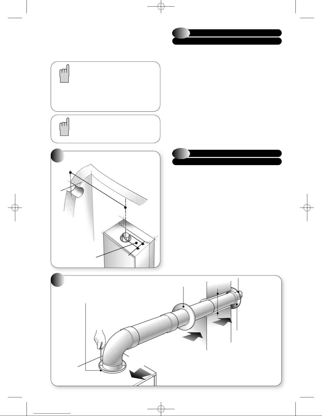
a) Measure the required flue length as shown in Figure 13. Refer to
AIR/FLUE DUCT INSTALLATION
section 2.5 to determine whether any extension kits are required.
Installations using only the standard ducts or standard ducts with
straight extensions are described in this section. Installation
instructions for all other flue systems are included in the various
flue kits.
17
Page 20
SINGLE PAGES 20/9/10 10:00 Page 20
b) Ensure that all (inner and outer tube) sealing rings are provided and
assemble the air/flue ducts as shown in the flue instructions.
c) Construct the correct flue length by building the flue out from the
appliance. Ensure that the flue and air seals are correctly fitted
before assembly and that each section is fully engaged.
The flue length is measured from the centreline of
the appliance flue outlet to the inside of the external
wall-sealing ring. In most cases it will be possible to
achieve the required flue length without cutting the
ducts, however where necessary the plain ends of
the extension ducts may be cut. Never cut the
swaged end, and always ensure that the cut is square
and free of burrs or debris.
NOTE IT IS ESSENTIAL THAT THE TERMINAL IS
FITTED THE CORRECT WAY UP.
See flue kit Instructions (i.e. rain shield at the top).
MEASURING THE EXACT FLUE LENGTH
13
TOTAL FLUE LENGTH
FROM OUTLET CENTRE
TO OUTSIDE WALL FACE:
WALL
FAN OUTLET
EXTERNAL
Dia. 60mm
= LENGTH
L
L
4.7.1
INSTALLING THE AIR/FLUE DUCT
FROM INSIDE THE ROOM
Wall thickness up to 800 mm (31in) only.
a) Push the terminal through the wall liner taking care to ensure that
the terminal is the correct way round and the external wall-sealing
ring does not become dislodged.
b) Assemble the flue system extension ducts as necessary, referring
to Figure 14.
c) Pull the flue system towards the appliance to seat the external
sealing ring against the outside wall, ensuring that the duct joints
are not disturbed.
d) Use the internal sealing ring to make good the internal hole, and
check that the terminal is correctly located on the outside wall
(Where possible this should be visually checked from outside the
building.) Figure 14 shows a view of the flue system, correctly
installed.
e) Finally locate and secure the elbow to the appliance using the four
screws provided.
4.7.2
INSTALLING THE AIR/FLUE DUCT
FROM OUTSIDE THE BUILDING
(Flue hole diameter 100 mm - wall liner not necessary)
a) Secure the flue elbow with seal to the appliance using 4 screws.
b) Fit external wall sealing ring over flue and then from outside the
building, push the flue system through the wall taking care to
ensure that the terminal is the correct way around.
c) Loosely fit the internal wall sealing ring over the inside end of the
flue.
d) Assemble the flue system extension ducts as necessary, referring
to the flue kit instructions, and fit to the flue elbow.
e) Fit the flue terminal to the flue system, ensuring that the duct joints
are not disturbed, and that the external sealing ring is seated
against the outside wall.
f) Finally use the internal sealing ring to make good the internal hole.
Check that the external wall sealing ring and the terminal is
correctly located, on the outside wall from outside the building.
14
INSTALLING THE FLUE SYSTEM FROM
INSIDE THE ROOM
FIBRE
SEAL FITTED
18
INTERNAL WALL
SEALING RING
2 ALIGN ASSEMBLED FLUE
SYSTEM ELBOW TO
APPLIANCE AND SECURE
3 SLIDE
INTERNAL
WALL
SEALING RING
TO WALL TO
FORM A GOOD
SEAL
130mm Dia.
HOLE WITH
WALL LINER
1 INSERT
ASSEMBLED
FLUE SYSTEM
FROM INSIDE
THE ROOM.
EXTERNAL
WALL
SEALING RING
OPENS
TOP
EXTERNAL WALL
SEALING RING
Page 21
SINGLE PAGES 20/9/10 10:00 Page 21
4.8
ELECTRICAL CONNECTIONS
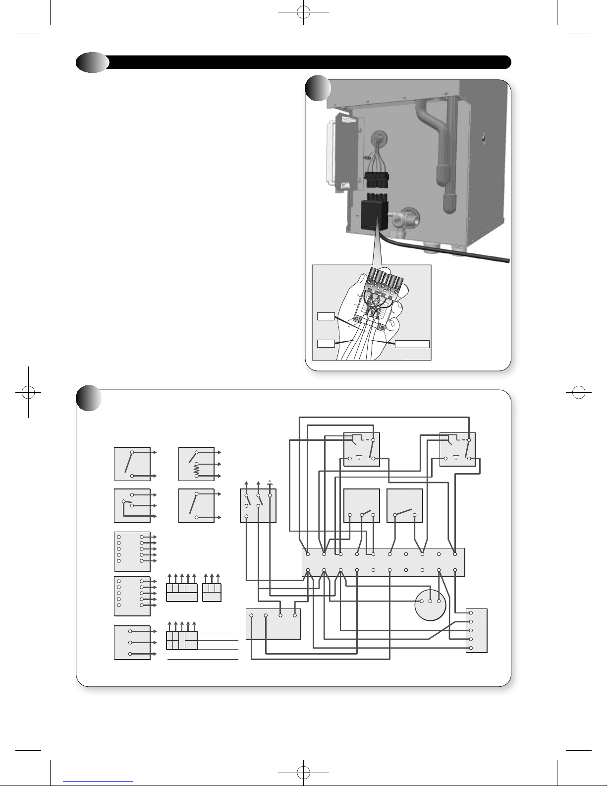
Connect the electricity supply and external controls (using suitable
mains cable) as follows:
Wire the cable(s) into the appropriate connections in the electrical plug
provided, referring to Figure 15. Live supply to L1, Neutral and Earth as
indicated. Check that L2 and L3 are linked.
To provide correct cable retention, fit the piece of tubing supplied over
the cable as it passes through the clamping arrangement. The cable will
be held in position as the plug cover is fitted.
If a programmer/room thermostat is to be fitted remove the red link
between L2 and L3 and connect the device across these terminals. Any
external controls fitted must be rated at 230V 50Hz and have volt free
contacts.
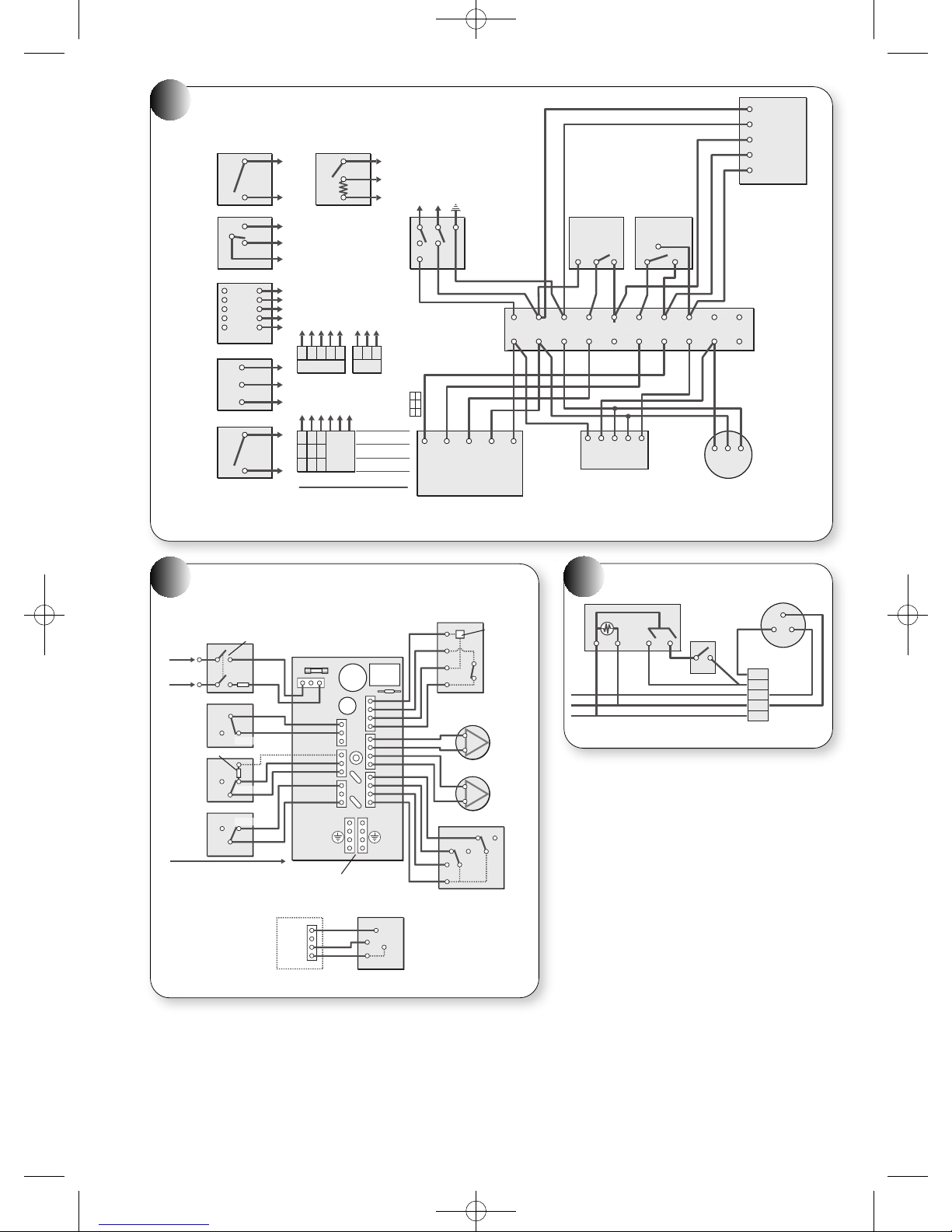
15
MAINS
PUMP
L3
N
L2
L1
PROGRAMMER
16
FULLY PUMPED ‘S’ PLAN
C
A
B
1
2
Brown
Blue
Grey
Orange
Green/
yellow
Brown
Blue
Grey
Orange
Green/
yellow
L
N
E
CT200
Room
thermostat
L641A
Cylinder
thermostat
V4043H
Heating
valve
V4043H
Hot water
valve
230V
mains input
Or
4
5
6
Not
used
8
5
2
1
10
3
8
2
1
10
3
1
2
3
1
3
2
T6360B Room thermostat
1
3
Optional
T4360A
Frost thermostat
Opens heating
circuit only
910 3 2 1 9 2 3
21 EN L LN E
Boiler Pump
2= Pump live
1=Switched live
L=Permanent live
6432
1
63
34
Honeywell ST6998 1002
L
N
(Link L-5-3)ST 799A
ST6400 ST6300
L
N
ST6200
Programmer
V4043H
Zone valve
4
5
230V 50Hz
2
LN
1
5
HW HTG N L
Time
controller
Brown
Grey
Grey
Blue
Motor Motor
Blue
Green
Yellow
T6360B
Room
thermostat
213 1 C
Green Yellow
34567
heating
L641A
Cylinder
thermostat
8 9 1021
Pump
Brown
Orange
ELN
Orange
V4043H
Zone valve
DHW
Boiler
L3
N
E
L2
L1
19
Page 22
SINGLE PAGES 20/9/10 10:00 Page 22
17
FULLY PUMPED ‘Y’ PLAN
C
A
B
1
2
White
Blue
Grey
Orange
Green/
yellow
L
N
E
1
3
CT200
Room
thermostat
L641A
Cylinder
thermostat
V4073A
Mid
position
valve
230V
mains input
Optional
T4360A
Frost
thermostat
Opens
heating
circuit only-use with
programmers with spot switching
Or
4
1
3
5
2
T6360B Room thermostat
6
7
6
5
2
7
8
98321 923
3
21 EN L LN E
1
2= Pump live
1=Switched live
2
L=Permanent live
3
7643
1
1734
5
Boiler
63
34
Pump
21
Honeywell ST6998 1002
L
N
(Link L-5-3)ST 799A
ST6400 ST6300
L
N
ST6200
L
N
Programmer
Blue
Green/yellow
4
V4073A
Mid
position
zone
valve
5
230V 50Hz
2
LN
HW
Off
On
HTGHW
Time
controller
NL
T6360B
Room
thermostat
213
L641A
Cylinder
thermostat
C
34567
L2
L1
L3
N
E
Boiler
White
Orange
Grey
1
2
8 9 1021
ELN
Pump
Pump live
Permament live
Switched live
18
Fused switched
isolator
N
L
Frost
thermostat
Internal
heater resistor
Room
thermostat
Cylinder
thermostat
E
UPP15-50 PUMP PLAN
WIRING CENTRE CONNECTIONS
3mm air gap
Fuse 2.5A
Programmer
CH on
HW on
N
L
N L
C
NO
N
N/U
N
NO
C
C
N
N/U
NO
Earth terminals for
Controls,Boiler,Pumps,
Electrical mains supply.
N
L
N/U
N/U
N/U
Fuse
3A
Demand
Demand
Demand
N
L
S/L
P/L
L
N
L
N
CH on
HW on
N
L
Boiler
N
L
S/L
P/L
CH/HW programmer
HW on
N
L
Basic time clock
L
N
L
N
CH on
N/U
Boiler controls
or gas solenoid
Boiler pump
over run
HW Pump
CW Pump
N/U
19
TYPICAL PROGRAMMER
Room
thermostat
Heating
Hot water
Earth
Neutral
230V fused 3 amp
Pump live
L2
Switched
L3
live
E
N
Permament
L1
live
Boiler
Terminals
Pump
20
Page 23
SINGLE PAGES 20/9/10 10:00 Page 23
5
COMMISSIONING & TESTING
5.1
Before commissioning the appliance, the whole gas installation
including the meter MUST be purged and tested for gas tightness in
accordance with BS 6891: 1988.
Before commencing the commissioning procedure, ensure that the gas
service cock is turned on, the electricity supply is isolated, and that the
CH pipe-work is complete. Fill the water systems by following the
procedure detailed below in steps a) and b), and referring to Figure 20.
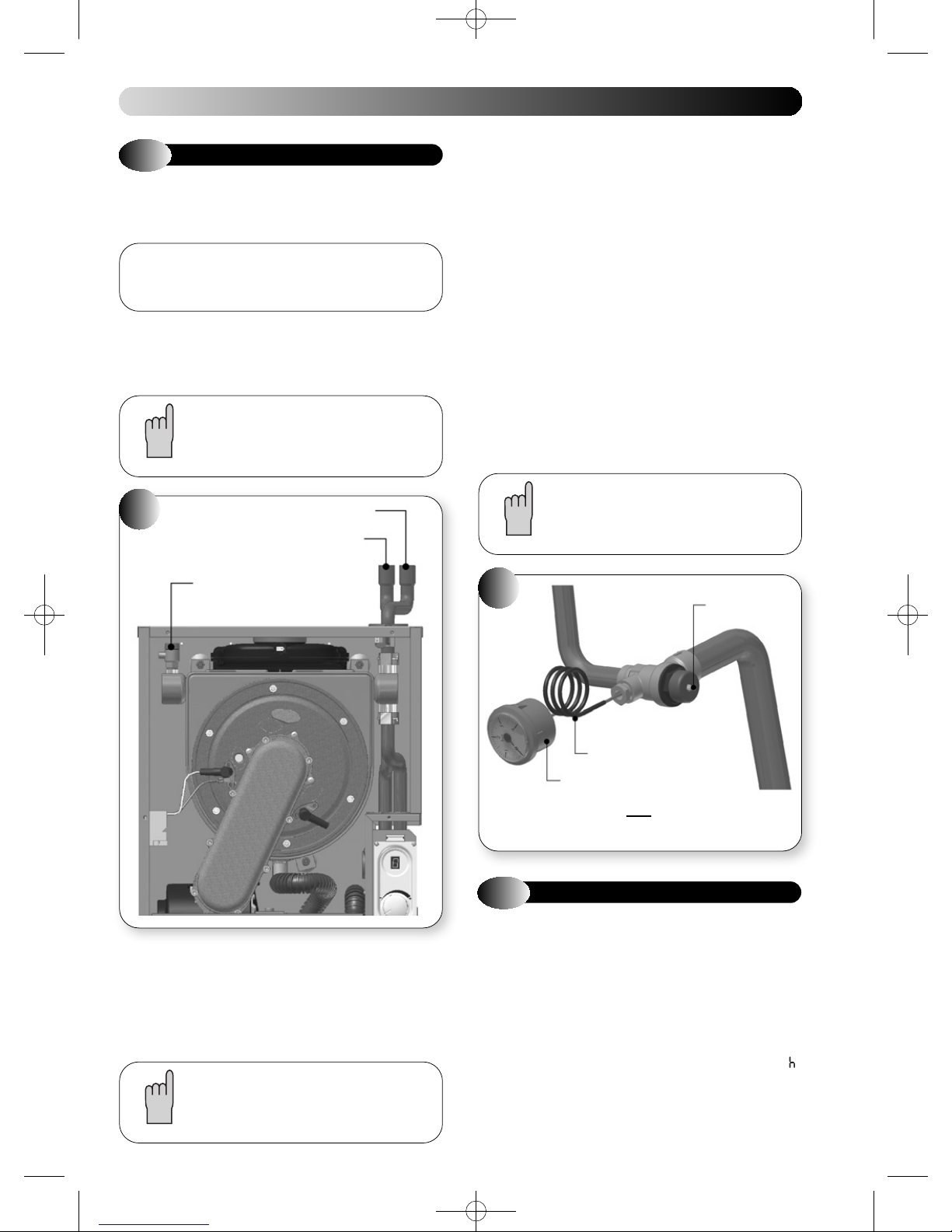
20
FILLING THE WATER SYSTEM
Open all doors and windows, extinguish naked lights,
!
and DO NOT SMOKE whilst purging the gas line.
It is recommended, where possible, to flush the CH
system without the appliance fitted, to avoid debris
and flux blocking the waterways within the
appliance.
CH FLOW
CH RETURN
Check the system for soundness.
Drain the entire system to flush out any debris, and refill making sure
that all the air is properly vented from the system and pump. Repeat
this instruction with the system hot. It is recommended that the system
be cleaned with a recognised system cleaner such as Fernox or Sentinel.
Prior to lighting the appliance to check the gas rates, the central heating
system should be checked for circulation by operating the appliance with
the gas turned off, this is to ensure that no air locks occur. The appliance
may go into ignition lockout and require resetting.
b) Sealed Systems
Fill the system until the pressure gauge registers 2.0 bar. Clear any
locks and check for soundness.
Check the operation of the pressure relief valve (figure 21) by lifting the
lever on the valve gently to ease the valve of its seat. Checking that water
is discharged, release the lever and ensure that the valve seats correctly
and does not leak. Where this is not possible a manual check should be
carried out.
Release the cold water to the initial design pressure.
Do not use the pressure relief valve to drain the
system, because dirt or debris could prevent the
valve seating correctly. If the valve leaks or sticks
closed, then replace it.
MANUAL BLEED
VALVE
a) All Systems
A competent person in accordance with the current issue of BS6798
should carry out commissioning.
Fill the system with cold water. Vent the system via the radiator valves
and system air vents in accordance with normal practice. Ensure that
all system air vents are closed.
To aid venting, a manual air vent is provided on the
LHS of the heat exchanger.
21
PRESSURE GAUGE CAPILLARY
PRESSURE GAUGE
THESE COMPONENTS ARE NOT SUPPLIED
BY HALSTEAD BOILERS LTD.
5.2
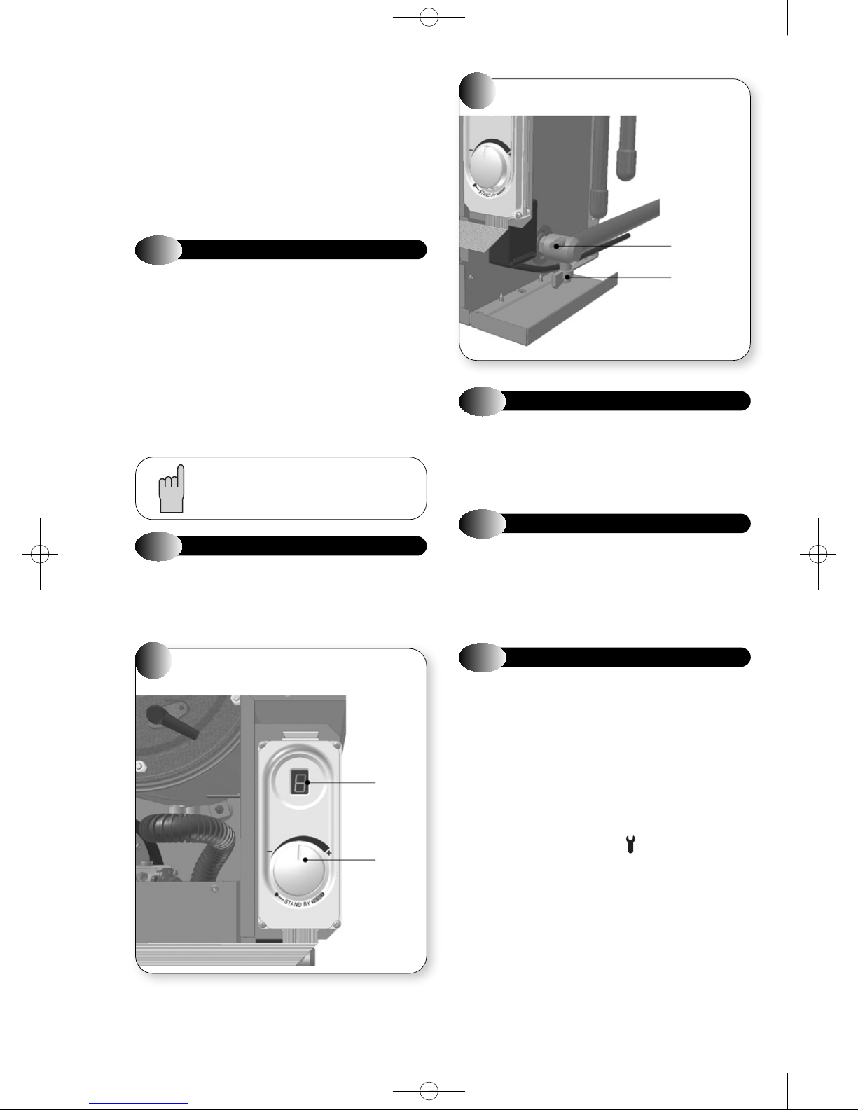
Refer to Figure 22
a) Slacken the screw in the appliance inlet pressure test point and
b) Check that the gas supply is turned ON and the gas service cock is
c) Switch on the electrical supply.
d) Turn the CH temperature Control knob to the midpoint between the
e) Ensure programmer and room thermostat (if fitted) are calling for
f) The display changes to '
COMMISSIONING THE APPLIANCE
connect a suitable manometer. Refer to Figure 23.
OPEN.
minimum and maximum setting. The display changes from '
heat.
seconds an ignition will commence.
NOTE
H
'. The fan should start and after a few
PRESSURE
RELIEF
LEVER
o
' to ' '.
21
Page 24
SINGLE PAGES 20/9/10 10:00 Page 24
g) If the burner fails to light the fan will stop. Initially this may be due
to air in the gas supply line. The boiler will automatically have five
attempts at ignition. It may be necessary to turn the CH
Temperature Control knob fully anti-clockwise to reset position
and repeat (d). (See section 5.4).
h) When the boiler has lit the display will show '
appliance to run for at least 10 minutes and check that the gas
supply pressure measured at the appliance inlet pressure test
point is 20 ± 1 mbar for natural gas, and 37 ± 1 mbar for propane
appliances.
5.3
a) Turn off the appliance and remove the manometer. Tighten the
b) Fit the appliance casing as illustrated in Figure 24. Position and
c) Fit the appliance hinged front panel in position with two screws at
d) Set the CH Temperature Control to the required setting. Set the
FINAL CHECKS
appliance inlet pressure test point screw. Re-light the burner and
test for gas tightness.
secure both side panels and the decorative front cover with screws
at the top and bottom.
the top and bottom.
room thermostat (if fitted) to the required setting. Refer to hot water
cylinder instructions.
If the boiler is connected to a hot water cylinder the
CH temperature has to be set to high.
H
.'. Allow the
INLET PRESSURE TEST POINT
23
GAS INLET
PRESSURE
TEST POINT
GAS SERVICE
COCK
5.5
The appliance is fitted with a frost protection device. In the event of very
cold conditions, the external pump may operate and the appliance light
for a few minutes to protect the appliance and system from potential
frost damage. This can only function if the gas and electricity supplies
are maintained.
FROST PROTECTION
5.4
In the event of failure during an ignition sequence, (5 attempts) the LED
displays fault code '
Temperature Control anticlockwise
to 'ON' within two seconds.
22
LOCKOUT / RESET INDICATION
3
'. In order to reset the boiler turn the CH
to 'STANDBY' position and then back
FASCIA PANEL AND CONTROLS
7
SEGMENT
DISPLAY
CH
CONTROL
KNOB
SET TO
MEDIUM
5.6
The appliance incorporates flow and return thermostats, which monitor
the operating temperature. Abnormal temperatures such as
overheating will cause the appliance to go to lockout and the LED display
will show code '
Temperature Control knob fully anti-clockwise to the reset position to
clear.
5.7
The following additional features are included in the appliance
specification:
ANTI-CYCLE DEVICE:
When the appliance cycles on its central heating control thermostat, a
slow cycle device operates. The timer (set to 5 minutes) is activated after
the end of each burn cycle to prevent rapid cycling of the burner.
CH SOFT START DEVICE:
After every burner start the burner output stays at low for 3 minutes,
to ensure smooth heat up of the system and maximum efficiency.
SERVICE MODE:
The appliance enters the SERVICE mode by turning the control knob
fully clockwise. The LED displays a flashing '
appliance runs at the minimum CH output. This mode allows the boiler
emissions to be measured.
OVERHEAT PROTECTION
1
'. Allow the appliance to cool and turn the CH
OTHER FEATURES
H
.'. In this mode the
22
Page 25
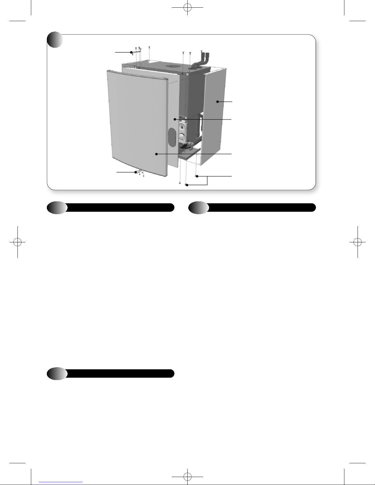
SINGLE PAGES 20/9/10 10:00 Page 25
24
CASING
TOP HINGE
SIDE PANEL
DECORATIVE FRONT
COVER
HINGED FRONT PANEL
BOTTOM HINGE
5.8
Upon completion of commissioning and testing the system, the installer
must instruct the user in how to operate the appliance by drawing the
user's attention to the following.
a) Give the 'Users Instructions' to the householder and emphasise
b) Explain and demonstrate the lighting and shutdown procedures.
c) Advise the householder on the efficient use of the system, including
d) Advise the user of the precautions necessary to prevent damage to
e) Explain the function of the CH Temperature Control knob, and how
f) Stress the importance of an annual service by a registered heating
g) The electrical mains supply to the appliance must remain ON for the
5.9
A logbook is supplied with this appliance to record installation and
commissioning details and to make future servicing of the appliance
easier. The logbook is found at the rear of this Installation and Servicing
Instruction manual.
This logbook forms part of the industry's Benchmark code of practice
for the installation, commissioning and servicing of central heating
systems.
Please ensure that the logbook is fully completed and left with the
customer for future reference, along with Users Instructions and this
Installation and Servicing Instruction manual.
USER INSTRUCTIONS
their responsibilities under the 'Gas Safety (Installation and Use)
Regulations or rules in force.
the use and adjustment of all system controls for CH.
the system, and to the building, in the event of the system remaining
inoperative during frost conditions.
to reset the appliance. Emphasise that if cutouts persists, the
appliance should be turned off and the installer or service engineer
consulted.
engineer.
frost protection circuit to operate.
APPLIANCE LOG BOOK
SIDE AND FRONT
SECURING SCREWS
5.10
Appliances may be converted from one gas group to another. It is
possible to convert between Propane and Natural gas by use of
conversion kits. The kits comprise the following:
Propane to Natural Gas
Kit Numbers 955128 - Eden Vbx 18
Natural Gas to Propane
Kit Numbers 955129 - Eden Vbx 18
Instruction on how to convert the appliance is given in the conversion
instructions supplied with these kits. However, particular attention
should be given to the fitting of the gas valve and the use of the Boiler
Chip Card (BCC).
For further information contact: Halstead Glen Dimplex service helpline
Tel: 0844 371 1111.
GAS CONVERSION
955126 - Eden Vbx 30
Conversion Instructions
Gas Control Valve
Data Badge (Natural Gas)
Boiler Chip Card Nat Gas
Cork Gasket
Polydome Badge (Natural Gas)
955127 - Eden Vbx 30
Conversion Instructions
Gas Control Valve
Data Badge (Propane)
Boiler Chip Card Propane
Cork Gasket
Polydome Badge (Propane)
23
Page 26
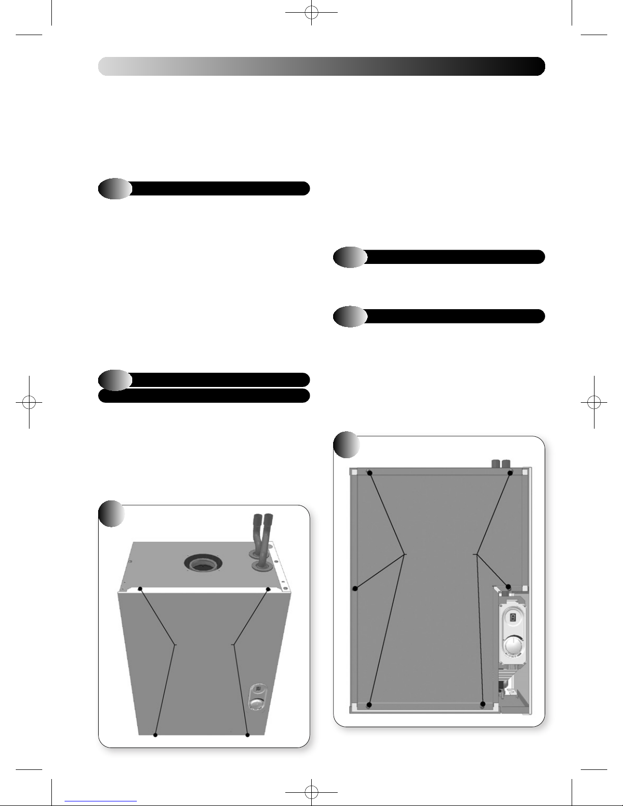
SINGLE PAGES 20/9/10 10:00 Page 26
6
ROUTINE SERVICING
To ensure continued efficient operation of the appliance, it is
recommended that it is checked and serviced as necessary at regular
intervals. The frequency of servicing will depend upon the particular
installation conditions and usage, but in general once a year should be
adequate. It is the law that a competent person, such as British Gas or
other CORGI registered personnel, must carry out any service work.
Service the appliance by following the full procedure detailed below:
6.1
The appliance incorporates a flue sampling point on the appliance flue
elbow, or appliance vertical flue adaptor. If the service engineer has
suitable equipment to analyse the flue gas, the sampling cap may be
removed and an adequately sized sample tube fitted. Operate the
appliance in Service mode, (see section 5.7). After ten minutes operation
check the CO
section 2.3. If the combustion figures are not within the limits shown in
section 2.3 refer the section 9.3.1 Combustion check set-up.Do not
forget to replace the sampling cap after use.
When the appliance is operating at maximum output check that the gas
supply pressure is 20.0 mbar, using the inlet pressure test point, located
on the gas cock.
Before commencing any service operation, ISOLATE the mains electrical
supply, and TURN OFF the gas supply at the main service cock.
6.2
Refer to Figures 25, 26, 27, and 28
a) Remove the hinges and take off the hinged front panel.
b) Remove the decorative front cover (4 screws).
c) Remove the sealed chamber door (6 screws)
d) Disconnect the igniter plug, earth lead and detection plug from the
COMBUSTION CHECK
/CO values and compare with those figures stated in
2
GAS CONTROL, VALVE,
FAN & BURNER ASSEMBLY
igniter and detection electrodes.
e) Unscrew the screw holding the gas valve lead plug, and disconnect
the plug.
f) Disconnect the electrical leads from the fan (2 plugs).
g) Undo the nut holding the gas valve feed pipe to the gas isolating
cock, and disconnect.
h) Remove the gas control valve, fan & burner assembly, by carefully
pulling forward the combustion chamber front and rotating the
assembly anticlockwise so that the burner points forward, then
disengage the gas valve feed pipe from the casing, by lifting up the
assembly. Take care not to damage the insulation.
i) The assembly may then be inspected.
j) Re-assemble in reverse order.
6.3
Inspect, and if necessary clean the main burner ports using a soft brush
or vacuum cleaner. Do not use a wire brush or any abrasive material.
6.4
a) Inspect the ignition and detection electrodes in situ. If necessary,
b) Check that the alignments of the ignition and detection electrodes
26
BURNER
IGNITION & DETECTION ELECTRODES
clean using a soft brush. If either the electrode or the ceramic
insulation shows signs of damage or wear, replace the electrode(s)
and their gasket.
are correct. Refer to Figure 29. Adjust by carefully bending the tip of
the electrode rod whilst supporting the base of the rod. Do not put
any pressure on the ceramic insulation.
COMBUSTION CASE PANELS
25
CONTROL PANEL
FIXING SCREWS
24
FIXING SCREWS
Page 27
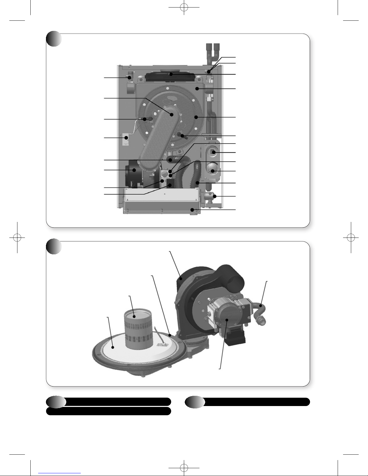
SINGLE PAGES 20/9/10 10:00 Page 27
27
VBX
MANUAL BLEED VALVE
BURNER ASSEMBLY
IGNITION ELECTRODE
IGNITION MODULE
CONDENSATE DRAIN PIPE
GAS CONTROL VALVE
GAS VALVE LEAD AND PLUG
FAN
CH RETURN THERMISTOR
CH FLOW THERMISTOR
FLUE GAS SENSOR
PRIMARY HEAT EXCHANGER
COMBUSTION CHAMBER
FRONT COVER
DETECTION ELCTRODE
OFFSET PRESSURE TEST POINT
CONTROL DISPLAY
MAX CO
THROTTLE
2
ADJUSTMENT
USER CONTROL
CONDENSATE TRAP
GAS ISOLATING COCK
CONTROL BOX
28
GAS CONTROL VALVE,
FAN & BURNER ASSEMBLY
6.5
COMBUSTION CHAMBER
INSULATION
COMBUSTION CHAMBER
FRONT COVER
BURNER
FAN
& HEAT EXCHANGER
Inspect the inside of the combustion chamber for debris. If necessary,
clean the inside of the tubes with a soft brush. Do not brush the
insulation at the rear, check the integrity of the combustion chamber
insulation panels, if damaged they will require replacement.
GAS VALVE
FEED PIPE
GAS VALVE
6.6
CONDENSATE DRAIN
The condensate Drain has a removable cap, Figure 30, which allows the
removal of debris that may be caught within it. Place a bowl under the
cap to catch the condensate and remove the cap. Any debris inside will
be expelled at this point. Replace the cap ensuring a good seal is made.
Discard the condensate and debris.
25
Page 28
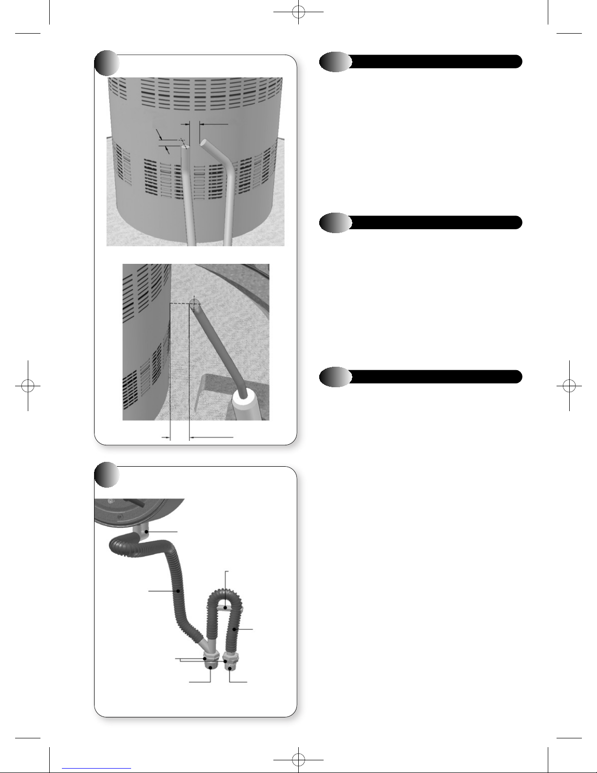
SINGLE PAGES 20/9/10 10:00 Page 28
29A SPARK ELECTRODE
29
6mm
TO BURNER
29B DETECTOR ELECTRODE
4mm ±0.5
6.7
a) Check the operation of the pressure relief valve as described in
b) Check the correct operation of the pressure gauge by noting the
c) Check that the system is at its original (cold) design pressure. If
d) In case of heavy pressure fluctuations during the heat and cool down
6.8
a) Re-assemble all components in reverse order.
b) Check that all joints and seals are correctly fitted.
c) Turn on the gas and electricity supply and light the appliance, as
d) Re-perform a combustion check, as described in section 6.1.
e) Check the operation of the appliance in CH mode.
f) Remove the manometer and tighten the inlet pressure test point
g) Test for gas tightness.
SEALED WATER SYSTEM
section 5.1 (b).
reading when cold and check that the pressure increases with
temperature. Replace the gauge if readings are suspect.
necessary, re-pressurise the system as described in section 5.1 (b)
and search for and rectify any leaks causing loss of water.
cycle, check the pre-charge pressure of the expansion vessel. If the
air pressure is less than 0.75 bar recharge vessel with an air pump.
RE-ASSEMBLY & RE-COMMISSIONING
described in section 5.2.
sealing screw.
30
CONDENSATE DRAIN
FLOW TUBE
LOCK NUTS
6mm ±0.5
SUMP ADAPTOR
PIPE RETAINING
CLIP
TRAP
TUBE
6.9
a) Ensure the sealed chamber door is secure with the six fixing screws.
b) Re-fit all decorative casing panels.
c) Return all appliance and external controls (if fitted) to their original
FINAL CHECKS
settings.
DRAIN SUMP CAP
26
CONDENSATE
DRAIN
Page 29
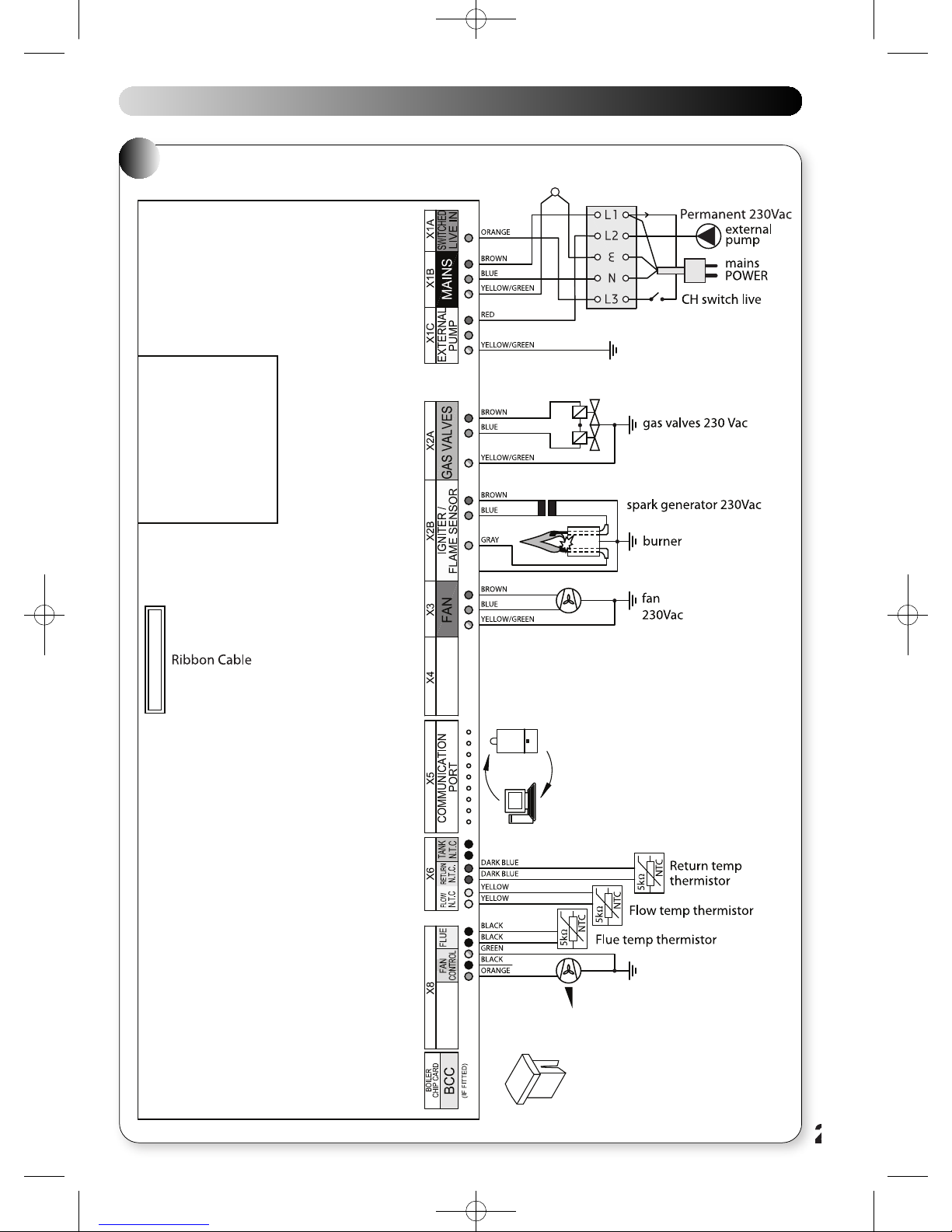
SINGLE PAGES 20/9/10 10:00 Page 29
31
7
INTERNAL WIRING DIAGRAMS
7.1 FUNCTIONAL FLOW WIRING DIAGRAM
27
Page 30
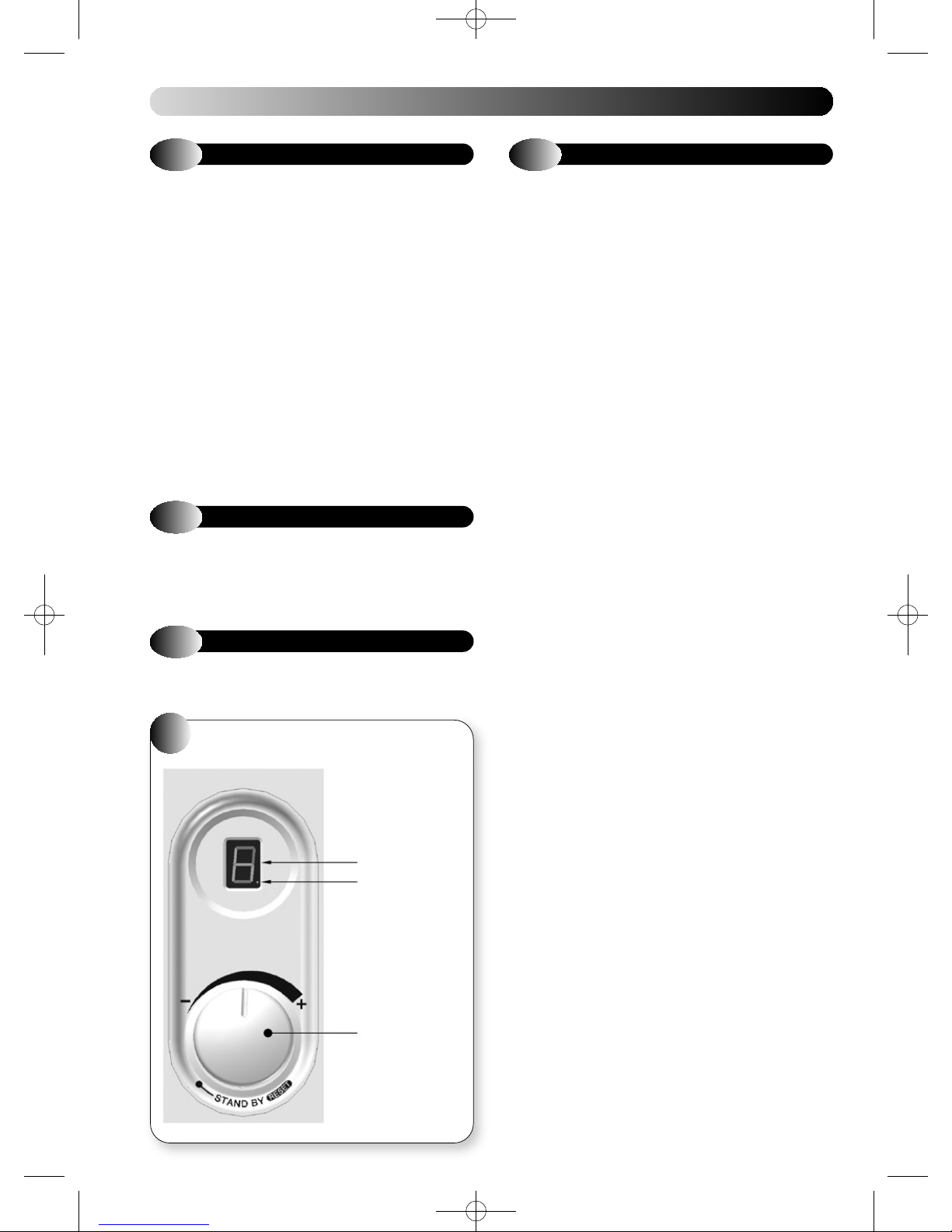
SINGLE PAGES 20/9/10 10:00 Page 30
8
FAULT FINDING
8.1
Before looking for a fault condition, check that:
G
G
G
G
Before attempting any electrical fault finding, always conduct the
preliminary electrical system checks as described in the Instructions
for the British Gas Multimeter, or other similar instrument.
On completion of any service or fault finding operation involving making
or breaking electrical connections, always check for EARTH
CONTINUITY, POLARITY and RESISTANCE TO EARTH.
Detailed procedures for replacing faulty components are described in
section 9 (Parts Replacement).
For further information contact: Halstead Glen Dimplex service helpline
Tel: 0844 371 1111.
8.2
FASCIA PANEL - Refer to Figure 32.
The LED shows code '3' in a lockout condition.
For fault finding refer to the diagnostic chart shown below.
GENERAL
The mains electrical supply is turned on.
The room or cylinder/tank thermostat (where fitted) are calling
for heat.
The gas service cock is open.
The system is at design pressure.
DIAGNOSTIC LED INDICATORS
8.4
Upon a demand for Central Heating, (closure of the time switch and
room thermostat, where fitted), the controls should carry out a set of
start up checks, followed by an ignition sequence. Refer to Section 5.2.
If the control has powered up correctly but does not respond to a CH
demand. Remove plug cover and check voltage between L3 (orange) and
N (blue). If 0 V ac, check external programmer / room thermostat. If 230
V ac, check control for lockout or blocking codes, (refer to section 8.3),
check operation of the external pump.
Note: Whenever a CH demand is removed, an anti cycle mode is initiated
which prevents the appliance from firing in CH mode for 5 minutes.
Ensure that the control is not in this mode by removing power from the
control and restoring it after a delay of 10 seconds.
If the Switch Live input is OK and no lockout or blocking code exists and
the control is not in anti– cycle mode, then replace PCB.
CENTRAL HEATING FAULT FINDING
8.3
In the event of the appliance failing to light, refer to the Diagnostics
Chart.
32
FAULT FINDING CODES
FASCIA PANEL
7 SEGMENT
DIGITAL DISPLAY
‘BURNER LIT’
INDICATOR DOT
CH CONTROL KNOB
28
Page 31
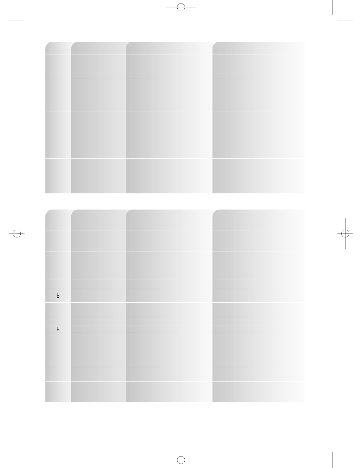
SINGLE PAGES 20/9/10 10:00 Page 31
RESET LOCK-OUT CODES
LED CODE FAULT/EFFECT REASON ACTION
1
2
3
4
Overheated appliance Water temperature greater than 105 °C
Water flow failure or
Differential check faulty/
Flame for a short period
only
No gas or Lockout flame Low gas pressure.
signal/No flame, Lockout No flame signal on ignition,
after 5 attempts or loss of signal during ignition
Flue gas sensor/ Flue gas temperature greater than 95 °C
No flame
Sensor temperature differential incorrect
G Check no air is in heat exchanger/CH system
G Check external pump operation
G Check PCB/X1C connector
G Check flow thermistor
G Check water pressure
G Check external pump/CH system blockage
G Check no air is in heat exchanger/CH system
G Check flow, and return sensors
G Check wires to sensors not crossed
G Check gas supply
G Check gas service cock
G Check gas valve and lead
G Check detection electrode lead
G Check PCB/X2A & X2B connectors
G Check spark generator/spark electrode
G Check mains earth lead continuity
G Check flue sensor
G Check flue system
G Check no air is in heat exchanger/CH system
G Check pump
G Check PCB/PCB connectors
BLOCKING CODES
5
6
7
A
C
E
O
P
NOTE: RPM SIGNAL - FAN SPEED SIGNAL IN REVOLUTIONS PER MINUTE
Defective sensor/No flame Defective flow, return or flue sensor
Defective gas valve/
Flame continues after
demand ends
Defective fan/No flame Missing or Erroneous RPM signal
PCB error/No flame Internal error G Check PCB
Activate BCC/No flame New BCC
Safety system failure/
No flame G Check BCC is initialised
BCC error/No flame Incorrect /missing BCC G Reseat or replace BCC
No flame No demand/Faulty connector G Check PCB/X1A connector
Differential check faulty/
Flame for 15 seconds
Error in power supply/
No flame G Check PCB connectors
No light indication Defective power supply
BCC - BOILER CHIP CARD (A SMALL MICROCHIP THAT PUSH FITS ONTO THE CONTROL PCB AND ALTERS OPERATING PARAMETERS)
(ONLY FITTED TO CERTAIN MODELS)
FAULT CODES 1-4 CAN BE RESET BY FOLLOWING THE PROCEDURE IN SECTION 5.4. HOWEVER, IF ANY OTHER FAULT CODE IS
SHOWING PLEASE CONTACT YOUR INSTALLER OR THE HALSTEAD GLEN DIMPLEX SERVICE HELPLINE: 0844 371 1111.
5 sec flame signal after
burner is switched off
Failure of internal self checking system
Water flow rate too low
Low mains voltage
G Check flow, return and flue sensors
G Check wiring to sensors
G Check PCB/X6 & X8 connectors
G Check gas valve and lead
G Check PCB
G Check fan
G Check mains fan lead & connector
G Check low voltage fan lead & connector
G Check PCB/X3 connector
G Turn CH control knob to reset twice
to activate
G Check PCB
G Check water pressure
G Check external pump/CH system blockage
G Check no air is in heat exchanger/CH system
G Check flow, and return sensors
G Check wires to sensors not crossed
G Check mains voltage
G Check power supply
G Check PCB/X1B connector
G Check PCB fuse
29
Page 32
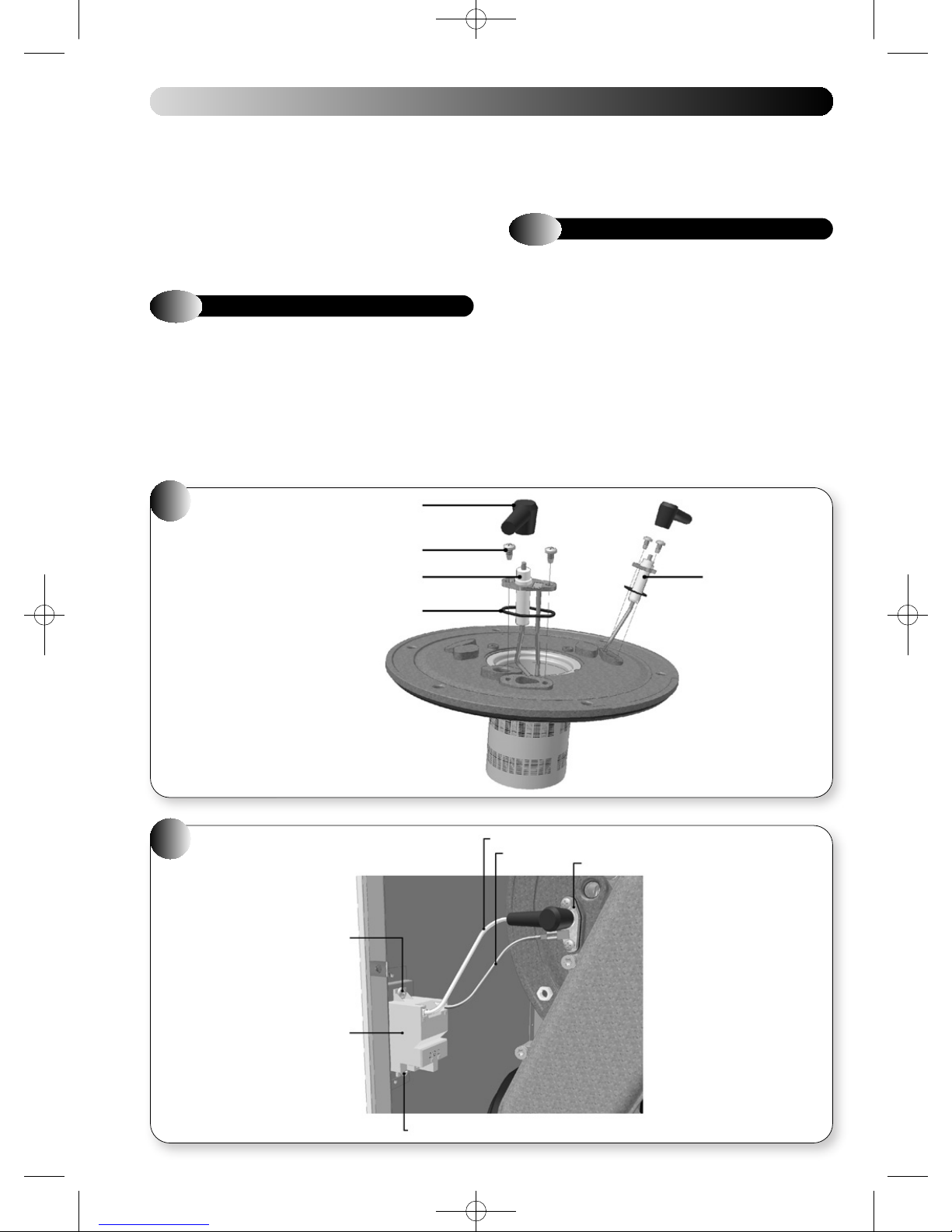
SINGLE PAGES 20/9/10 10:00 Page 32
9
REPLACEMENT OF PARTS
Before commencing any service operation, ISOLATE the mains electrical
supply and TURN OFF the gas supply at the main service cock.
Replacement of most parts first requires the removal of the sealed
chamber front panels; refer to section 6.2.
There may be some slight water spillage; so electrical components
should be protected.
It is the law that any service work must be carried out by a registered
person.
9.1
Refer to Figure 33
a) Ensure supply voltage is isolated, and that the gas supply is isolated.
b) Remove the gas control valve, fan & burner assembly; refer to
c) Unscrew the two screws holding the electrode, remove electrode,
d) Fit the new electrode, and new gasket.
33
IGNITION & DETECTION ELECTRODES
section 6.2.
and used gasket.
IGNITION & DETECTION
ELECTRODES
ELECTRODE
PLUG
SCREW
e) Check that electrode is aligned as detailed in Figures 29(a) or 29(b).
f) Re-assemble in reverse order. Ensure that all joints and seals are
correctly re-fitted.
9.2
Refer to Figure 34
a) Ensure supply voltage is isolated.
b) Remove the plug and earth lead from the ignition electrode.
c) Remove the electrical supply leads.
d) Unscrew the two screws holding the ignitor unit, remove ignitor
e) Fit the new ignitor unit.
g) Re-assemble in reverse order; ensure that the ignitor unit is
h) Ensure that all joints and seals are correctly re-fitted.
IGNITOR UNIT & IGNITION LEADS
unit.
orientated as shown in Figure 34, and that the brown electric supply
lead is fitted to position 1 on the igniter unit.
34
IGNITOR UNIT AND IGNITION LEADS
ELECTRODE (IGNITION)
GASKET
SCREW
IGNITION LEAD
EARTH LEAD
ELECTRODE (DETECTION)
IGNITION ELECTRODE
IGNITION
MODULE
30
SCREW
Page 33
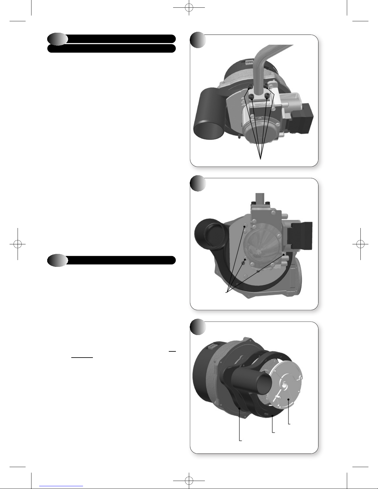
SINGLE PAGES 20/9/10 10:00 Page 33
9.3
GAS CONTROL VALVE
INCLUDING AIR INLET COWL
Refer to Figures 35, 36 & 37
a) Ensure supply voltage is isolated, and that the gas supply is isolated.
b) Remove the gas control valve, fan & burner assembly; refer to
section 6.2.
c) Unscrew four screws holding the gas feed pipe, and remove gas feed
pipe, refer to Figure 35.
d) Unscrew three torx screws (T-20), and remove gas control valve,
refer to Figure 36.
e) Unclip the top section of the black plastic air inlet cowl from the fan
assembly, and remove white plastic insert, clean or replace as
necessary, refer to Figure 37.
f) Refit or replace the top section of the black plastic air inlet cowl,
ensuring that it is clipped into place and that the holes in the white
plastic insert are aligned with the fixing holes.
g) Attach and secure the gas feed pipe to the replacement gas valve,
using a new gasket.
h) Attach and secure the replacement gas control valve to the fan
assembly.
i) Re-assemble in reverse order; ensure that all joints and seals are
correctly re-fitted.
Note: The gas control valve is factory set and sealed and is not
adjustable. If the gas control valve is changed, then when the appliance
is running, the flue gas CO
and compared to the values stated in Performance Data, section 2.2. If
the measured value does not correspond to the Performance Data, then
follow section 9.3.1 below or contact: Halstead Glen Dimplex service
helpline Tel: 0844 371 1111.
should be measured, refer to section 6.1,
2
35
36
GAS FEED PIPE
4 SCREWS
GAS CONTROL VALVE
9.3.1
If a new gas valve is fitted or the existing gas valve is not within the
quoted CO
values (see Combustion set-up table on the following page).
GAS VALVE REPLACEMENT INSTRUCTIONS
The Eden VBX 18 and 30 are category II
The appliances are supplied for use on Natural Gas (G20) at a supply
pressure of 20 mbar or Propane (G31) at a supply pressure of 37 mbar
but can be converted from NG to Propane or vice versa, using specific
conversion kits. They are certified to comply with the requirements of
EN 483 for use in GB and IE only.
!
a) The combustion values at minimum gas rate and maximum gas rate
b) Do not attempt to adjust the gas valve unless you have a suitable
COMBUSTION CHECK SET-UP
values it must be adjusted to operate within the quoted CO
2
appliances.
2H3P
It is the law that all gas appliances are installed and
maintained by a competent person such as a Corgi
registered installer, in accordance with the rules in force.
It is in your own interest, and that of safety, to ensure that
the law is complied with. Failure to do so could lead to
prosecution.
The following instructions are intended for guidance and
in no way override any Statutory Requirements.
must be checked using a suitably calibrated Flue Gas analyser.
Compliance with BS7967-2, BS7967-3 and BS7967-4 is required.
Flue Gas analyser that is checked and within calibration.
Compliance with BS7967-2, BS7967-3 and BS7967-4 is required.
2
37
3 TORX
SCREWS
AIR INLET COWL
SWIRL PLATE
AIR INLET COWL TOP
AIR INLET COWL BOTTOM
31
Page 34
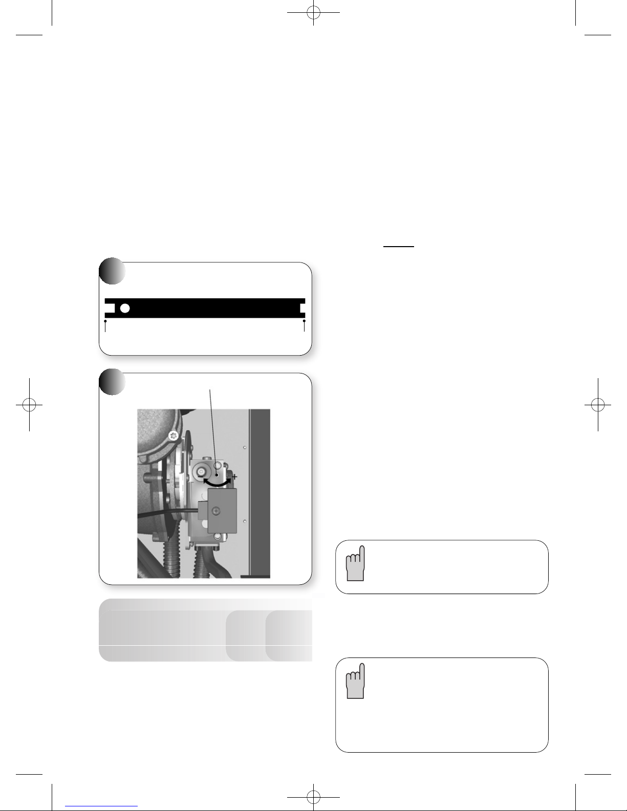
SINGLE PAGES 20/9/10 10:01 Page 34
RE-COMMISSIONING
Before commissioning the appliance, the whole gas
installation including the meter must be purged and
!
IMPORTANT: Open all doors and windows; extinguish naked flames
a) Before switching the appliance ON ensure that the Throttle
• FULLY wind out the throttle adjuster screw by rotating it counter
• Using the relevant end (Nat Gas or LPG as shown in fig.38) of the
38
USE THIS END FOR NAT GAS USE THIS END FOR LPG
39
tested for gas tightness.
and do not smoke whilst purging the gas installation pipe work.
Adjuster screw (Fig. 39) is adjusted to the correct dimension as
follows:-
clockwise using a conventional flat bladed screw driver.
tool provided, rotate the throttle adjuster screw clockwise until the
tool bottoms out on the body of the gas valve. The dimension from
the valve body to the top of the throttle adjuster screw head should
then correspond with ‘Dimension X’ shown in the Combustion setup table below.
THROTTLE ADJUSTMENT TOOL
MAX. THROTTLE ADJUSTER
• Switch the appliance on and ensure that the clock and room
thermostat (if fitted) are calling for heat and that all radiators are
open.
c) To set the boiler into Service Mode at Minimum rate:-
• Set the control knob clockwise until it stops in approximately the 5
o’clock position. Note:- the knob will turn past the horizontal
maximum temperature mark. The boiler is now in ‘
with the fan speed at Minimum rate and the digital display will show
a flashing ‘
• Check the Minimum rate combustion readings are within the required
values shown in section 2.3.
d) For service mode at Maximum rate first set the boiler to minimum
rate (see ‘c’ above) :-
• Turn the CH control knob back to normal operation mode and within
3 seconds back to ‘
Maximum rate.
e. Check the Maximum
required values shown in section 2.3.
• If the combustion readings are outside the values shown in section
2.3 then adjustment of the gas valve is required (See Section 6).
ADJUSTMENT OF GAS VALVE
Refer to section 2.3 for the Carbon Dioxide (CO
Maximum Gas Rate.
• Set the boiler into Service mode at Maximum rate (see sections ‘c’
& ‘d’ above).
Adjust the CO
39.
NOTE: Only turn the throttle in small steps of no more than 1/8th of
a turn and wait for 1 minute after each adjustment for the
combustion reading to stabilise.
Anti-clockwise to increase CO
Clockwise to decrease CO
• After setting the Carbon Dioxide (CO2) in accordance with section
2.3 put the boiler into Service mode at Minimum rate (See sections
‘c’ above)
• Check the Minimum rate combustion readings are within the
required values shown in section 2.3.
• Once all adjustments are complete seal the throttle adjustment screw
and ensure the sampling cap is replaced on the flue sample point.
COMPLETION
H
’
Service mode
by turning the Max Throttle Adjuster as shown in fig.
2
’. The fan speed will now increase to
rate combustion readings are within the
2
2
Service mode
) set points at
2
’
Combustion Set up table
Dimension ‘X’ (measured from valve
body to top of screw) (nominal)
Applies to all models
b) Combustion checks
The CO (Carbon Monoxide) & CO
values quoted in Section 2.3. Combustion checks must be carried out
at Minimum and Maximum Gas rate.
• A suitable, calibrated flue gas analyser is required. The appliance
incorporates a flue sampling point on the flue socket. The cap of the
sampling point should be removed and the sample tube inserted into
32
the middle of the inner flue pipe.
(Carbon Dioxide) must be within the
2
Nat Gas Propane
4.5mm 3.0mm
If CO2(Carbon Dioxide) and CO (Carbon Monoxide) are not
within the range stated in Section 2.3 please call Halstead
Glen Dimplex service helpline for additional information
about adjustment of the gas valve. Tel: 0844 371 1111.
Finally, set the heating and hot water controls to the user’s
requirements. Where fitted ensure that the clock override switch is in
the timed position and check that the time clock is set at the desired
time periods. Set the room thermostat and tank/cylinder thermostat, (if
fitted) to the required setting(s)
If the gas control valve is changed, then it is imperative
that it is commisioned as per the instructions provided
with the new gas valve. The flue gas CO
the values quoted in section 2.3 of this manual. If this is
not the case then contact: Halstead Glen Dimplex service
helpline Tel: 0844 371 1111.
Always seal the gas valve adjustment screw withpaint
after adjustment.
must be within
2
Page 35
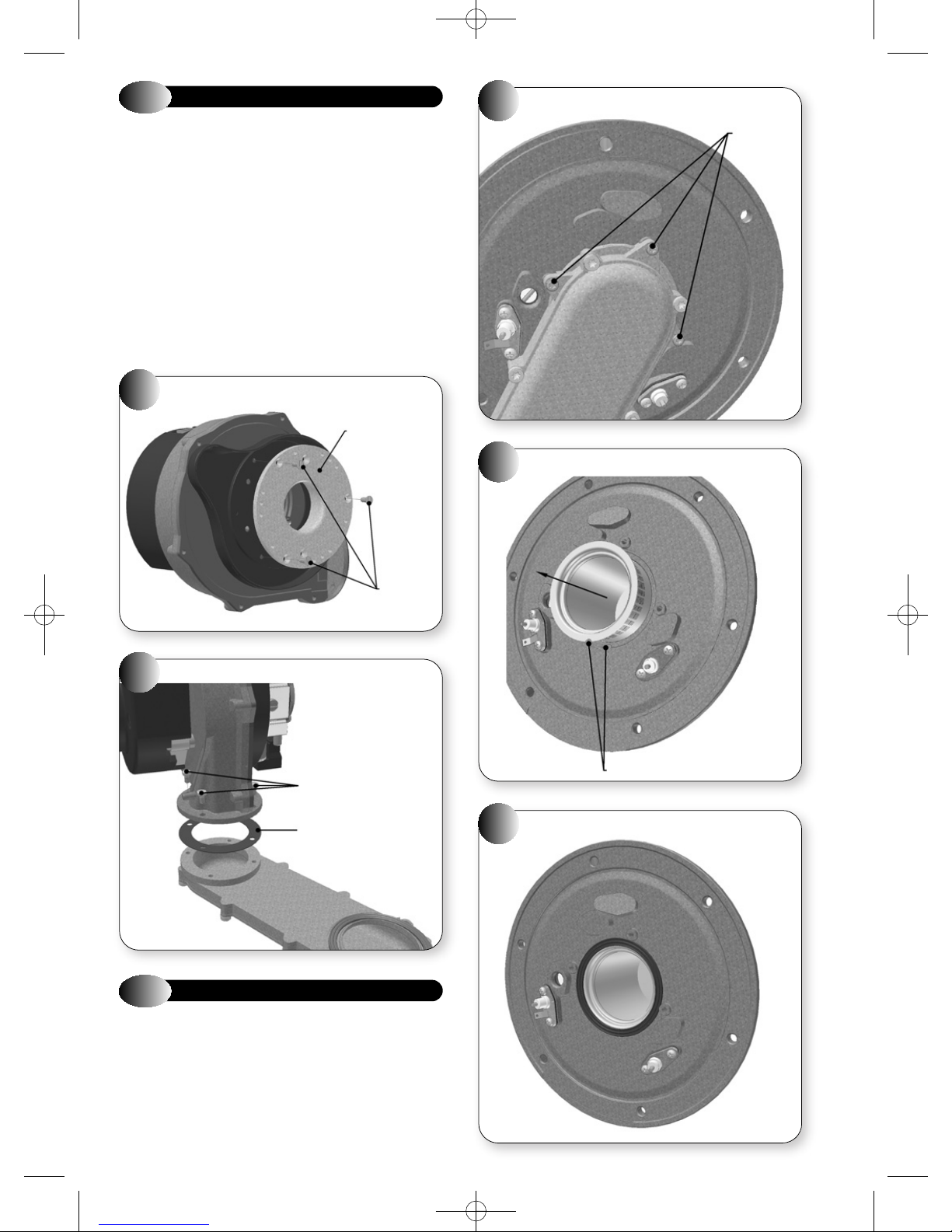
SINGLE PAGES 20/9/10 10:01 Page 35
9.4
Refer to Figures 37, 40 and 41.
a) Ensure supply voltage is isolated, and that the gas supply is isolated.
b) Remove the gas control valve, fan & burner assembly; refer to
c) Remove the gas control valve; refer to section 9.3.
d) Unscrew the three screws holding the gas valve mounting plate,
e) Unscrew the four screws holding the fan to the burner manifold, and
f) Attach and secure the replacement fan, replace the gasket.
g) Re-assemble in reverse order; ensure that all joints and seals are
40
FAN
section 6.2.
remove plate; refer to Figures 36 and 40.
remove fan; refer to Figure 41.
correctly re-fitted.
GAS VALVE MOUNTING PLATE
GAS VALVE
MOUNTING PLATE
MANIFOLD MOUNTING SCREWS
42
43
WITHDRAWING BURNER
3 TORX
SCREWS
3 SCREWS
FAN MOUNTING SCREWS
41
4 SCREWS
GASKET
9.5
Refer to Figures 42, 43 & 44
a) Ensure supply voltage is isolated, and that the gas supply is isolated.
b) Remove the gas control valve, fan & burner assembly; refer to
c) Unscrew the three torx screws, (T-25), holding the manifold to the
BURNER
section 6.2.
combustion chamber front cover, and remove the manifold; refer to
Figure 42.
44
LOCATING TAB
BURNER GASKET
33
Page 36
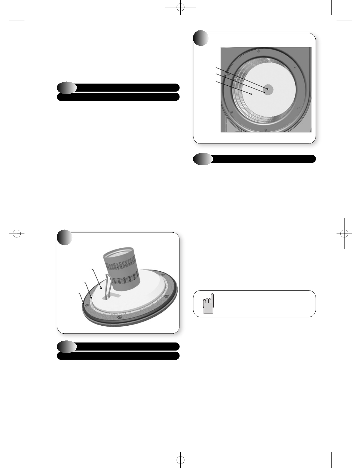
SINGLE PAGES 20/9/10 10:01 Page 36
d) Remove the gasket, and withdraw the burner; refer to Figure 43.
e) Fit replacement burner, taking care not to damage the insulation,
and ensure burner is correctly located by lining up the locating tab.
f) Fit new gasket; refer to Figure 44.
g) Re-assemble in reverse order; ensure that all joints and seals are
correctly re-fitted.
9.6
COMBUSTION CHAMBER
FRONT INSULATION
The design of the appliance is such that the combustion chamber
insulation should not require replacement unless mechanically
damaged. It is recommended that to prevent dust, the insulation be
dampened prior to removal, and that a protective mask is worn when
changing or handling the insulation material.
Refer to Figure 45
a) Ensure supply voltage is isolated, and that the gas supply is isolated.
b) Remove the gas control valve, fan & burner assembly; refer to
section 6.2.
c) Remove the electrodes; refer to section 9.1.
d) Remove the burner: refer to section 9.5.
e) Replace the combustion chamber front insulation.
f) Re-assemble the burner and electrodes, using new gaskets.
g) Check the position of the electrodes: refer to section 6.4.
h) Re-assemble in reverse order; ensure that all joints and seals are
correctly re-fitted.
COMBUSTION CHAMBER FRONT INSULATION
45
FRONT
INSULATION
INNER
SEAL
OUTER
SEAL
COMBUSTION CHAMBER REAR INSULATION
46
SCREW
WASHER
REAR
INSULATION
9.8
Refer to Figures 14 & 47
a) Ensure supply voltage is isolated, and that the gas supply is isolated.
b) Remove the gas control valve, fan & burner assembly; refer to
c) Disconnect the electrical leads to the flue sensor, flow sensor and
d) Drain down the appliance.
e) Disconnect the flue system from the appliance, 4 screws, and lift up
f) Remove the retaining clip from the heat exchanger flow outlet; refer
g) Gently pull up (or down, depending on installation) to disengage the
h) Remove the retaining clip from the heat exchanger return inlet.
i) Rotate the return pipe clockwise and gently pull down to disengage
HEAT EXCHANGER
section 6.2.
return sensor.
to disengage the flue from the flue hood; refer to Figure 14.
to Figure 47.
flow pipe from the heat exchanger.
the return pipe from the heat exchanger.
It may be necessary to cut both flow and return pipes
to disengage them from the heat exchanger.
9.7
COMBUSTION CHAMBER
REAR INSULATION
Refer to Figure 46
a) Ensure supply voltage is isolated, and that the gas supply is isolated.
b) Remove the gas control valve, fan & burner assembly; refer to
section 6.2.
c) Use an Allen key to undo the central screw holding the rear
insulation in place.
d) Remove old insulation and fit replacement, ensuring locating
washer is in front.
e) Re-assemble in reverse order; ensure that all joints and seals are
34
correctly re-fitted.
j) Disconnect the condensate drainpipe from the condensate drainpipe
sump adaptor; refer to section 9.12.
k) Unscrew the three nuts holding the heat exchanger to the back
panel; refer to Figure 47.
l) Remove the heat exchanger.
m) Disconnect the condensate drainpipe sump adaptor from the heat
exchanger.
n) Remove the flue hood from the heat exchanger, two screws, and fit
the flue hood onto the new heat exchanger, Check integrity of the
flue hood seals and replace as necessary. Remove the manual air
vent and vent tube from the heat exchanger and fit onto to new heat
exchanger; refer to Figure 47.
o) Fit the condensate drainpipe sump adaptor to the heat exchanger
and flue hood.
p) Re-assemble in reverse order; check integrity of the flow and return
pipe 'O' rings and fibre washers and replace as necessary. Ensure
that all joints and seals are correctly re-fitted.
Page 37
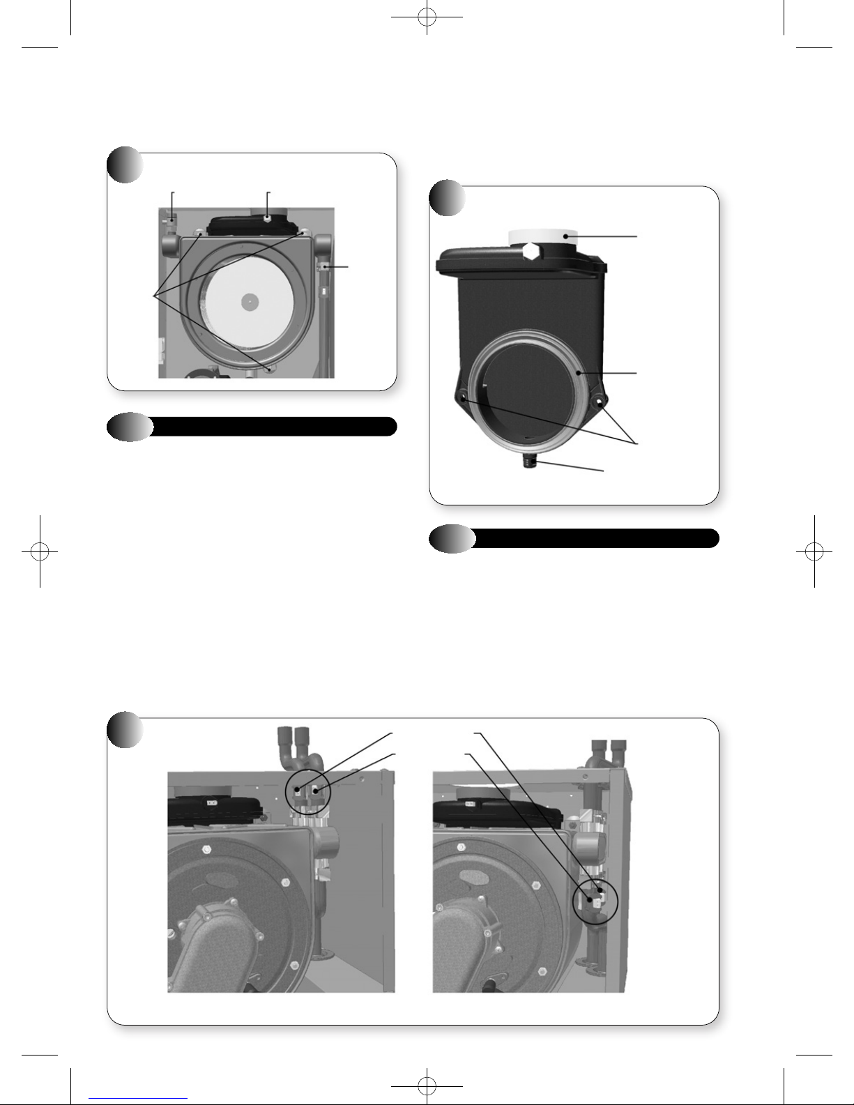
SINGLE PAGES 20/9/10 10:01 Page 37
q) Open the isolating cocks and vent air from the system using the
manual air vent. Re-pressurise the system as necessary and check
for water leaks.
Note: It is likely that the heat exchanger will still contain water.
HEAT EXCHANGER
47
MANUAL AIR VENT FLUE SENSOR
RETAINING
CLIP
FIXING
POINTS
9.9
Refer to Figures 48
a) Ensure supply voltage is isolated, and that the gas supply is isolated.
b) Remove the gas control valve, fan & burner assembly; refer to
c) Remove the heat exchanger: refer to section 9.8.
d) Disconnect the condensate drainpipe sump adaptor from the heat
e) Remove the existing flue hood from the heat exchanger, two screws,
f) Fit the condensate drainpipe sump adaptor to the heat exchanger
g) Unscrew the flue sensor from the existing flue hood and fit onto the
FLUE HOOD
section 6.2.
exchanger; refer to section 9.12.
and fit the replacement flue hood onto the heat exchanger; use new
flue hood seals; refer to Figure 48.
and flue hood.
new flue hood; refer to section 9.16.
h) Re-assemble in reverse order; check integrity of the flow and return
pipe 'O' rings and fibre washers and replace as necessary. Ensure
that all joints and seals are correctly re-fitted.
i) Open the isolating cocks and vent air from the system using the
manual air vent. Re-pressurise the system as necessary and check
for water leaks.
48
9.10
Refer to Figure 49
a) Ensure supply voltage is isolated.
b) Disconnect the electrical lead from the sensor to be changed.
c) Unclip the sensor from the pipe and remove.
d) Clip the replacement sensor onto the pipe and position as shown in
e) Reconnect the electrical lead.
FLUE HOOD
WATER TEMPERATURE SENSORS
Figure 49.
FLUE SEAL
FLUE HOOD
GASKET
FIXING POINTS
CONDENSATE DRAIN
FLOW SENSOR
49
TEMPERATURE SENSOR POSITION WHEN
USING STANDARD TOP OUTLET PIPEWORK
RETURN SENSOR
FLOW SENSOR
TEMPERATURE SENSOR POSITION WHEN
USING OPTIONAL BOTTOM OUTLET PIPEWORK
35
Page 38
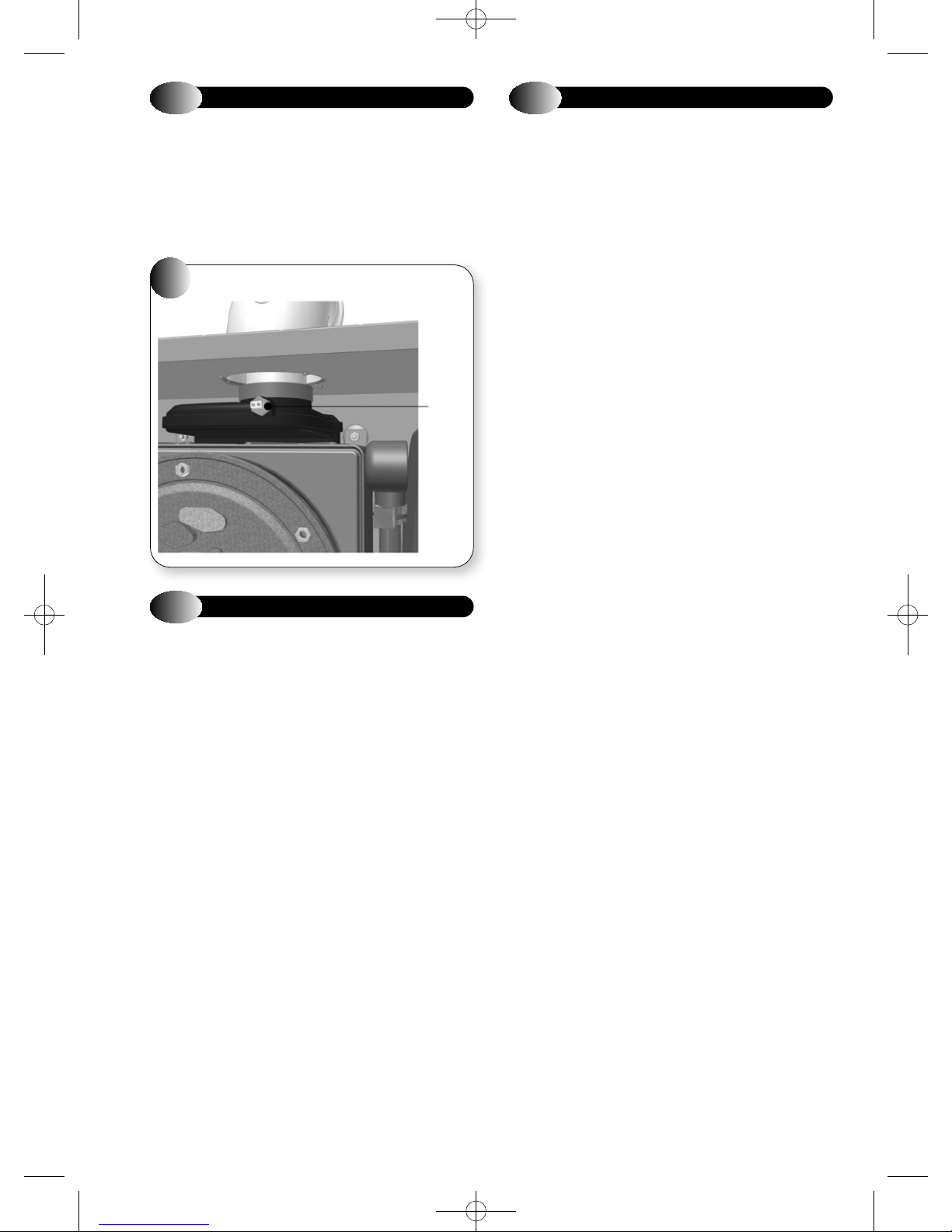
SINGLE PAGES 20/9/10 10:01 Page 38
9.11
Refer to Figure 50
a) Ensure supply voltage is isolated.
b) Disconnect the electrical lead from the flue sensor.
c) Unscrew the flue sensor and remove from the flue hood.
d) Fit the replacement flue sensor and reconnect the electrical lead (blue
50
FLUE SENSOR
plug).
FLUE SENSOR
FLUE
SENSOR
9.13
Note:- When replacing the control PCB it is important that the
instructions supplied with the new PCB are followed. Do not use any
old BCC cards.
The following is only a guide. Refer to Figures 22, 27 & 30
a) Ensure supply voltage is isolated.
b) Unclip the user interface from its housing (see figure 22).
c) Lower the controls front.
d) Unplug the electrical leads from the PCB. Refer to section 7.
e) Remove the PCB plastic cover.
f) Unclip the PCB and withdraw.
g) Fit the new PCB and BCC if required.
h) Re-assemble in reverse order.
i) If the boiler requires resetting turn the CH Temperature Control
CONTROL PCB
knob anti-clockwise to 'STANDBY' position and then back to 'ON'
within two seconds. Refer to section 5.4.
After fitting a new PCB always re-check the combustion of the boiler
to ensure it is within the values quoted in section 2.3.
If the combustion figures are not within the values quoted then
contact Halstead Glen Dimplex service helpline Tel: 0844 371 1111.
9.12
Refer to Figure 30
a) Ensure supply voltage is isolated.
b) Open the drain sump cap, while holding a receptacle beneath to
c) Disconnect the condensate drainpipe from the appliance.
d) Undo the two locknuts holding the system in place.
e) Detach the condensate drainpipe sump adaptor, by gently pulling
f) Remove the condensate drain system, clean or replace as
g) Re-assemble in reverse order; ensure that all joints and seals are
CONDENSATE DRAIN SYSTEM
capture any condensate.
down.
necessary.
correctly re-fitted.
36
Page 39
SINGLE PAGES 20/9/10 10:01 Page 39
10
SHORT PARTS LIST
Refer to Figure 51
Key G C Part No. Description No off Makers Pt No.
1 Ignition Electrode 988526
2 Detection Electrode 988527
3 Spark Generator Unit 500665
4 Gas Control Valve 988315
5 Fan Assembly 601016
6a Burner VBX 30 700602
6b Burner VBX 18 700600
7a Heat Exchanger (VBX 30) 451033
7b Heat Exchanger (VBX 18) 451034
8 Water Temperature Sensor 500661
9 Flue Sensor 500660
10 Manual Bleed Valve 300730
11 Control PCB 988491
12 User Interface 988492
Heat Exchanger Seal Kit 988489
37
Page 40
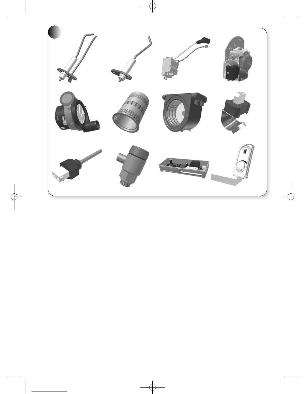
SINGLE PAGES 20/9/10 10:01 Page 40
51
1
5
9
2
6
10
3
7
11
4
8
12
38
Page 41
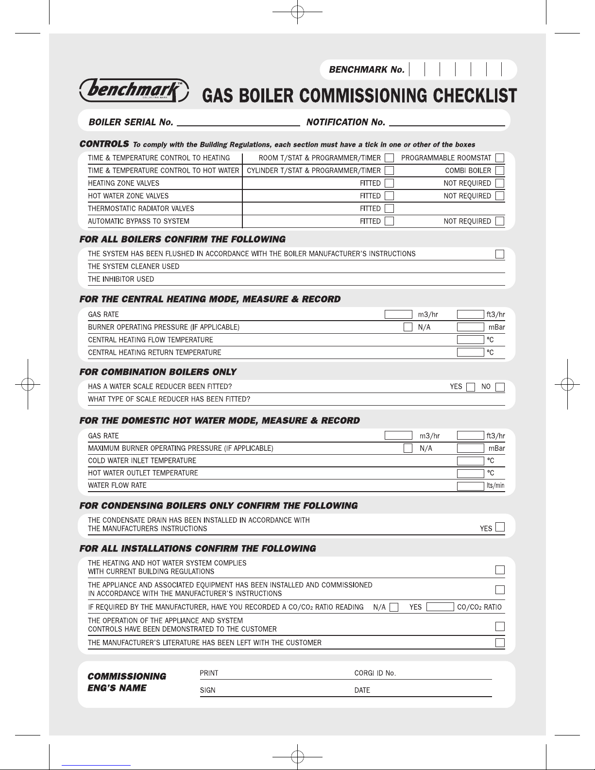
SINGLE PAGES 20/9/10 10:01 Page 41
Page 42
SINGLE PAGES 20/9/10 10:01 Page 42
Page 43

SINGLE PAGES 20/9/10 10:01 Page 44
Glen Dimplex Boilers, Stoney Lane, Prescot Merseyside L35 2XW.
For telephone enquiries call: 0844 371 1111.
Website: www.glendimplexboilers.com
Part of the Glen Dimplex Group
Glen Dimplex Boilers is continuously improving its products and may therefore change specifications without prior notice.
The statutory rights of the consumer are not affected.
07/10 751053 Issue 4
SALES AND SERVICE HELPLINE: 0844 371 1111
 Loading...