


G. C. APPLIANCE No. 41 333 77 Ace G. C. APPLIANCE No. 41 333 78 Ace High
0086
Ace and Ace High
Wall Mounted Gas Combination Boiler
Installation and Servicing Instructions
To be left with user adjacent to gas meter
EC 0087/BM/37

CONTENTS INTRODUCTION
1
The Halstead Ace and Ace High are fully automatic wall-mounted,
fan-assisted, balanced flue, gas combination appliances for use with
natural gas (G20). They incorporate a microprocessor based, fully
modulating, gas control system with direct burner ignition. The Ace High
has a higher domestic hot water heat output and provides a higher flow
rate.
Both the Halstead Ace and Ace High feature an attractive white stove
enamelled casing with an inset control panel. The flue elbow and air
ducts are also white stove enamelled to give a clean, attractive
appearance to the installation.
The Ace High provides both central heating and instantaneous domestic
hot water at outputs between 11 kW (37,500 BTU/h) and 30 kW
(102,000 BTU/h). The Ace provides both central heating and
instantaneous domestic hot water at outputs between 8.8 kW (30,000
Btu/h) and 24 kW (82,000 Btu/h).
Heat output is controlled according to demand (in both domestic hot
water and central heating mode) by the modulating gas control valve.
The appliance always gives priority to domestic hot water supply.
The appliance is supplied with a standard telescopic concentric air and
flue duct system suitable for flue lengths of up to 820mm (32in). The duct
assembly is connected to the boiler via a turret which can exit the boiler
in any horizontal direction. Horizontal extension ducts may be fitted in
accordance with and up to the maximum dimensions stated in these
instructions.
A vertical outlet kit is also available for installations where an outside
wall is not accessible and it is desired to fit the duct ‘through the roof’.
Installation using the standard flue kit is described in the main text of
these instructions and supplementary instructions at the rear of this
booklet describe installation involving the vertical outlet kit. NO OTHER
FLUE KITS OR EXTENSIONS MAY BE USED WITH THIS
APPLIANCE.
The appliance can be installed from inside the room without access to
the external wall providing that a wall liner is fitted and that the wall
thickness is less than 0.5m (19in).The wall liner is available as an
optional extra. See section 4 for further details. (Note: If the vertical
outlet kit is to be used, access to the roof is necessary).
The appliance is designed for use with sealed primary water systems
and incorporates a circulation pump, diverter valve assembly, pressure
gauge, flow switch, safety valve and system expansion vessel. A
separate DHW expansion vessel is not required. Isolation valves are
fitted to the service connections, and an automatic heating bypass is
fitted to maintain an adequate flow rate through the boiler.
If thermostatic radiator valves are installed we recommend that one
radiator is fitted with lockshield valves (normally in the bathroom) to
allow pump overrun circulation.
Internal frost protection is fitted as standard equipment. The boiler may
be used with any certified mains voltage room thermostat.
An electro-mechanical 24hr time clock is fitted as standard.
NOTE: British Standard BS7593: 1992 stresses the
importance of cleansing and flushing of the system to
ensure it continues to run efficiently with the minimum of
maintenance necessary. Halstead Boilers fully support this
professional approach and recommend that the system is
cleansed with an effective chemical cleanser and protected
long term with a suitable inhibitor. Such products are
available from Fernox and Sentinel.
Gas Consumer Council
The Gas Consumer Council (GCC) is an independent organisation which
protects the interest of gas users. If you need advice, you will find the
telephone number in your local directory under ‘Gas’.
1 GENERAL DESCRIPTION
2 TECHNICAL SPECIFICATIONS . . . . . . . . . . . . . . .1
2.1 Gas Categories . . . . . . . . . . . . . . . . . . . . . . . . . . . . .1
2.2 Performance data, Halstead Ace & Ace High . . . . . . . . . .1
2.3 Minimum clearances, Halstead Ace & Ace High . . . . . . .1
2.4 General specifications, Halstead Ace & Ace High . . . . . .1
2.5 Overall appliance dimensions . . . . . . . . . . . . . . . . . . . .1
2.6 Concentric air/flue duct specifications . . . . . . . . . . . . . .3
2.8 Exploded diagram . . . . . . . . . . . . . . . . . . . . . . . . . . . .6
2.9 Hydraulic circuit . . . . . . . . . . . . . . . . . . . . . . . . . . . . .7
3 INSTALLATION REQUIREMENTS . . . . . . . . . . . . . .8
3.1 Statutory requirements . . . . . . . . . . . . . . . . . . . . . . . . .8
3.2 Boiler location . . . . . . . . . . . . . . . . . . . . . . . . . . . . . . .8
3.3 Flue terminal position . . . . . . . . . . . . . . . . . . . . . . . . . .9
3.4 Ventilation requirements . . . . . . . . . . . . . . . . . . . . . . . .9
3.5 Gas supply . . . . . . . . . . . . . . . . . . . . . . . . . . . . . . . . .9
3.6 Central heating system . . . . . . . . . . . . . . . . . . . . . . . . .9
3.7 Domestic hot water systems . . . . . . . . . . . . . . . . . . . . .10
3.8 Electricity supply . . . . . . . . . . . . . . . . . . . . . . . . . . . .10
3.9 External controls . . . . . . . . . . . . . . . . . . . . . . . . . . . .10
4.0 INSTALLING THE APPLIANCE . . . . . . . . . . . . . . .12
4.1 Unpacking the appliance . . . . . . . . . . . . . . . . . . . . . .12
4.2 Preparing the wall . . . . . . . . . . . . . . . . . . . . . . . . . . .12
4.3 Mounting the boiler . . . . . . . . . . . . . . . . . . . . . . . . . .13
4.4 Service connections . . . . . . . . . . . . . . . . . . . . . . . . . .13
4.5 Gas connection . . . . . . . . . . . . . . . . . . . . . . . . . . . . .13
4.6 Pressure relief valve connection . . . . . . . . . . . . . . . . . .13
4.7 Air/flue duct installation . . . . . . . . . . . . . . . . . . . . . . .14
4.8 Wiring instructions . . . . . . . . . . . . . . . . . . . . . . . . . . .17
5 COMMISSIONING AND TESTING . . . . . . . . . . . .18
5.1 Filling the water system . . . . . . . . . . . . . . . . . . . . . . . .18
5.2 Commissioning the appliance . . . . . . . . . . . . . . . . . . .19
5.3 DHW flow rate . . . . . . . . . . . . . . . . . . . . . . . . . . . . .20
5.4 Final checks . . . . . . . . . . . . . . . . . . . . . . . . . . . . . . .20
5.5 Ignition lockout . . . . . . . . . . . . . . . . . . . . . . . . . . . . .20
5.6 Overheat thermostat . . . . . . . . . . . . . . . . . . . . . . . . . .20
5.7 Frost protection . . . . . . . . . . . . . . . . . . . . . . . . . . . . .20
5.8 Other features . . . . . . . . . . . . . . . . . . . . . . . . . . . . . .20
5.9 User’s instructions . . . . . . . . . . . . . . . . . . . . . . . . . . .20
5.10 Boiler logbook . . . . . . . . . . . . . . . . . . . . . . . . . . . . .20
6 ROUTINE SERVICING INSTRUCTIONS . . . . . . . . .21
7 INTERNAL WIRING DIAGRAMS . . . . . . . . . . . . .23
7.1 Functional flow diagram . . . . . . . . . . . . . . . . . . . . . . .23
7.2 Illustrated wiring diagram . . . . . . . . . . . . . . . . . . . . . .24
8 FAULT FINDING . . . . . . . . . . . . . . . . . . . . . . . .25
8.1 General . . . . . . . . . . . . . . . . . . . . . . . . . . . . . . . . . .25
8.2 Diagnostic indicator LED’s . . . . . . . . . . . . . . . . . . . . . .25
8.3 Ignition faults . . . . . . . . . . . . . . . . . . . . . . . . . . . . . .25
8.4 DHW fault finding . . . . . . . . . . . . . . . . . . . . . . . . . . .25
8.5 Central heating fault finding . . . . . . . . . . . . . . . . . . . .25
9 REPLACEMENT OF PARTS . . . . . . . . . . . . . . . . .27
9.1 Heat exchanger . . . . . . . . . . . . . . . . . . . . . . . . . . . . .27
9.2 Combustion chamber insulation . . . . . . . . . . . . . . . . . .27
9.3 Fan assembly . . . . . . . . . . . . . . . . . . . . . . . . . . . . . .27
9.4 Burner . . . . . . . . . . . . . . . . . . . . . . . . . . . . . . . . . . .27
9.5 Ignition and detection electrodes . . . . . . . . . . . . . . . . .27
9.6 Multifunctional gas control . . . . . . . . . . . . . . . . . . . . .27
9.6.1 Gas control replacement . . . . . . . . . . . . . . . . . . . . . . .27
9.6.2 Gas control and PCB burner pressure setting procedure . .27
9.7 Air Pressure switch . . . . . . . . . . . . . . . . . . . . . . . . . . .28
9.8 Overheat thermostat . . . . . . . . . . . . . . . . . . . . . . . . . .28
9.9 PCB . . . . . . . . . . . . . . . . . . . . . . . . . . . . . . . . . . . .28
9.10 CH/DHW Microswitches . . . . . . . . . . . . . . . . . . . . . .29
9.11 Thermistors D.H.W. or Heating . . . . . . . . . . . . . . . . . .29
9.12 Water flow regulator . . . . . . . . . . . . . . . . . . . . . . . . .30
9.13 DHW heat exchanger . . . . . . . . . . . . . . . . . . . . . . . .30
9.14 DHW flow switch body . . . . . . . . . . . . . . . . . . . . . . .30
9.15 Pump . . . . . . . . . . . . . . . . . . . . . . . . . . . . . . . . . . . .30
9.16 Pressure relief valve . . . . . . . . . . . . . . . . . . . . . . . . . .30
9.17 Pressure gauge . . . . . . . . . . . . . . . . . . . . . . . . . . . . .30
9.18 Auto air vent . . . . . . . . . . . . . . . . . . . . . . . . . . . . . . .30
9.19 System expansion vessel . . . . . . . . . . . . . . . . . . . . . . .31
9.20 Time clock. . . . . . . . . . . . . . . . . . . . . . . . . . . . . . . . .31
10 SHORT PARTS LIST . . . . . . . . . . . . . . . . . . . . . .31
11 Supplementary instructions for flue systems
with a vertical outlet. . . . . . . . . . . . . . . . . . . . . . . . . .32

Central
Heating
DHW
Max. gas rate (after 10 mins operation i.e. hot) 2.81 m3/h (100 ft3/h)
Factory set gas rate (after 10 min operation) 2.0 m3/h (71 ft3/h)
Min. domestic hot water flow rate 2.8 l/min (0.6 gpm)
Design domestic hot water performance 9.8/min (2.1 gpm) raised 35°C
Max. domestic hot water temperature 73+/-2°C
Max. mains water inlet pressure 10 bar (146 psi)
Min. mains water inlet pressure for operation 0.3 bar (4.4 psi)
Min. mains water inlet pressure for max heat output 1.0 bar (14.6 psi)
Max gas rate (after 10 mins operation, i.e. hot) 2.81 m3/h (100 ft3/h)
1
TECHNICAL SPECIFICATIONS
2
HALSTEAD ACE
HALSTEAD ACE HIGH
2.2
PERFORMANCE DATA
1
.
.
.
.
.
.
.
.
.
.
.
.
.
100mm DIA.
325mm
188mm
225mm
760mm
455mm
900mm
95mm
.
.
.
1(a)
200mm
5mm
200mm
5mm
SEE
NOTE
•
•
•
•
•
•
•
•
•
•
The appliances are Certified to comply with the requirements of
EN 483 and EN 625 for use in GB and IE (Great Britain and
Ireland) using the following gas categories:
Ace/Ace High: I
2H
(G20 with a governed gas supply at 20 mbar
(8 in.wg) inlet pressure)
The appliance classification (as defined in EN 483) may be any of the
following depending on the chosen flue option: C12 or C32.
2.1
GAS CATEGORIES AND
APPLIANCE CLASSIFICATION
2.3
MINIMUM CLEARANCES
Main burner injector ø 1.30 mm x 13
Total water capacity 1 litre
Minimum CH system pressure (static head) - Cold 0.5 bar
Maximum CH system pressure (static head) - Hot 2.5 bar
Empty weight 45.5kg
Max lift weight 35kg
Total weight (full) 46.5kg
Electrical supply 230V - 50 Hz Fuse at 3A
Internal fuses
F 4 amp ceramic
Maximum power consumption 160W
Max CH flow temperature 85°C 185°F
Integral expansion vessel capacity 8 ltr. capacity
Minimum clearances for installing and servicing the appliance refer to Fig. 1(b) below.
Gas 15mm compression
Central heating flow 22mm compression
Central heating return 22mm compression
Domestic water inlet 15mm compression
Domestic water outlet 15mm compression
Pressure relief valve outlet 15mm tail
CONNECTION SIZES
2.4
GENERAL SPECIFICATIONS
1(b)
NOTE:
10mm for normal
operation 450mm for
installation and servicing
2.5
OVERALL DIMENTIONS AND MINIMUM CLEARANCES
The Seasonal Efficiency (SEDBUK) is 78.1 % and conforms with Band D. The efficiency value
is used in the UK Government Standard Assessment (SAP) for energy rating of dwellings.
Central Max 24 (82,000) 26.6 (90,900) 29.5 (100,890) 9.5 (3.8)
Heating Min. 11.6 (39,670) 13.5 (46,220) 15.0 (51,300) 2.5 (1.0)
DHW Max 24 (82,000) 26.6 (90,900) 29.5 (100,890) 9.5 (3.8)
Min. 8.8 (30,000) 11.1 (36,360) 11.8 (40,350) 1.4 (0.5)
Factory 16.7 (57114) 18.6 (60000) 20.6 (70430) 6.0 (2.3)
set CH
MODE RATE OUTPUT INPUT INPUT BURNER
Net Gross PRESSURE
kw (Btu/h) kw (Btu/h) kw (Btu/h) mbar (in.wg)
GENERAL
Central
Heating
DHW
Max gas rate (after 10 mins operation, i.e. hot) 3.6 m3/h (128 ft3/h)
Factory set gas rate (after 10 min operation) 2.0 m3/h (100 ft3/h)
Min. domestic hot water flow rate 2.8 l/min (0.6 gpm)
Design domestic hot water performance 13.01 l/min (2.9 gpm) raised 35∞C
Max. domestic hot water temperature 73+/-2°C
Max. mains water inlet pressure 10 bar (146 psi)
Min. mains water inlet pressure for operation 0.3 bar (4.4 psi)
Min. mains water inlet pressure for max heat output 1.0 bar (14.6 psi)
Max gas rate (after 10 mins operation, i.e. hot) 3.6 m3/h (100 ft3/h)
The Seasonal Efficiency (SEDBUK) is 78.5 % and conforms with Band D. The efficiency value
is used in the UK Government Standard Assessment (SAP) for energy rating of dwellings.
Central Max 30 (102,400) 32.6 (111,547) 36.2 (123,800) 14.6 (5.8)
Heating Min. 11.0 (37,620) 13.5 (46,220) 14.2 (48,564) 2.4 (1.1)
DHW Max 30 (102,400) 32.6 (111,547) 36.2 (123,800) 14.6 (5.8)
Min. 8.8 (30,000) 11.1 (36,360) 11.8 (40,350) 1.4 (0.5)
Factory 16.7 (57,114) 18.6 (60,000) 20.6 (70,430) 6.0 (2.3)
set CH
MODE RATE OUTPUT INPUT INPUT BURNER
Net Gross PRESSURE
kw (Btu/h) kw (Btu/h) kw (Btu/h) mbar (in.wg)
GENERAL

2
2
EXAMPLES OF ALTERNATIVE FLUE SYSTEMS
•
STANDARD
TELESCOPIC
FLUE
•
FLANGED ELBOW
2(a) HORIZONTAL
STRAIGHT FLUE
SUPPLIED AS STANDARD
•
•
•
•
•
FLANGED ELBOW
STANDARD DUCT
(telescopic flue outer)
EXTENSION
DUCT
2(b) HORIZONTAL
STRAIGHT FLUE
•
TERMINAL
DUCT
•
EXTENSION DUCT
•
90° EXTENSION
ELBOW
•
STANDARD DUCT
•
VERTICAL
TURRET
SOCKET
2(c) RAISED
HORIZONTAL
STRAIGHT FLUE
3 COMPONENTS
AS SHOWN
•
TERMINAL
DUCT
•
EXTENSION
DUCT
•
VERTICAL
TURRET
SOCKET
•
90° EXTENSION
ELBOW
•
STANDARD
DUCT
•
90° EXTENSION
ELBOW
•
EXTENSION
DUCT
2(d) FLUE
WITH
90° BEND
•
TERMINAL
DUCT
•
STANDARD DUCT
•
FLANGED ELBOW
•
90° EXTENSION
ELBOW
•
•
EXTENSION
DUCTS
2(e) HORIZONTAL
FLUE WITH 90° BEND
2(f) VERTICAL
STRAIGHT FLUE
•
VERTICAL
COWL
•
EXTENSION
DUCT
•
EXTENSION
DUCT
•
EXTENSION
DUCT
•
STANDARD
DUCT
•
VERTICAL
TURRET
SOCKET
2(g) OFFSET
VERTICAL FLUE
•
•
EXTENSION
DUCTS
•
90° EXTENSION
ELBOW
•
FLANGED
ELBOW
•
STANDARD
DUCT
EXITS APPLIANCE
AT REAR OR
EITHER SIDE
2(h) TYPICAL VERTICAL
INSTALLATION USING
45° ELBOWS
•
VERTICAL
COWL
•
45° ELBOW
•
EXTENSION
DUCT
•
45° EXTENSION
ELBOW
•
STANDARD
DUCT
•
VERTICAL
TURRET
SOCKET
•
VERTICAL
COWL
TERMINAL DUCT
(telescopic flue inner)
EXTENSION
DUCT

3
The appliance is supplied complete with a standard telescopic flue
kit. This comprises a standard duct and a terminal duct and can
be used for flue lengths between 506mm and 820mm without
cutting the ducts. To use terminal duct for flue length between 300
and 506 mm the ducts need cutting. Avoid swarf and sharp edges
to maintain telescopic function
The following additional concentric kits are available as optional extras.
Extension duct (each extension extends the flue length by up to
767 mm)
90° Extension Elbow (Allows an additional bend in the flue
and has an ‘equivalent length’ of 767 mm.) This elbow is
mechanically different from the flanged elbow supplied as
standard with the appliance, but has the same equivalent length of
767mm.
45° Extension Elbow Allows an additional bend in the flue and
has an ‘equivalent length’ of 384mm.
Vertical Turret Socket (for use with elevated horizontal flues
and vertical cowls)
Vertical Roof Terminal. (For use where an external wall is not
available)
2.6
CONCENTRIC AIR/FLUE DUCT SPECIFICATIONS
3
SPECIFICATION FOR STANDARD AND EXTENDED STRAIGHT FLUES
(Refer to section 2.6(a) for maximum allowable lengths)
•
•
•
•
‘L’
‘S’
‘L’
‘R’
3(a)
•
•
‘L’
‘L’
3(b)
•
Fig 3a - Standard flue assembly using either
side or rear outlet.
Flue length ‘L’ (measured from the boiler outlet centre
line to the outside wall face) = max 820
‘R’ distance from boiler outlet centre to
rear of boiler = 188mm
‘S’ distance fron boiler centre to
side of boiler = 225mm
(Allow for minimum clearance of 5mm at side of boiler)
Fig 3b - Standard flue assembly with
optional straight extensions using either
side or rear outlet
Maximum flue length ‘L’ (measured from the boiler
outlet centre line to the outside wall face).
Ace = 4000mm, Ace High = 2000mm
These optional kits may be used with the standard flue kit to
produce an extensive range of flue options. Examples are illustrated
in Figure 2. Variations upon these illustrations may be used
providing that the following rules are strictly obeyed.
a) The maximum/minimum permissible allowable length of the flue
system is:
Ace
horizontal flue terminal - maximum 4000 mm (118 in)
vertical flue terminal - maximum 4618 mm (182 in)
horizontal flue terminal - minimum 300mm
vertical flue terminal - minimum 565 mm
Ace High
horizontal flue terminal - maximum 2000 mm (157 in)
vertical flue terminal - maximum 3851 mm (151 in)
horizontal flue terminal - minimum 300mm
vertical flue terminal - minimum 565 mm
•
•
•

4
4
SPECIFICATION FOR FLUE SYSTEMS
WITH AN EXTRA 90° ELBOW
a
b
Fig 4 - Use of the flanged elbow, extension(s), 90°
extension elbow, and standard flue assembly.
Maximum allowable flue length of ‘a’ + ‘b’ = Ace 3233mm,
Ace High 1233mm.
(i.e maximum horizontal flue lengths minus resistive length of
767mm for 90° extension elbow.)
5
SPECIFICATION FOR FLUE SYSTEMS
WITH AN ELEVATED FLUE SYSTEM
6
SPECIFICATION FOR FLUE SYSTEMS
WITH AN ELEVATED FLUE SYSTEM
INCORPORATING BENDS
•
•
b
a
•
•
•
•
•
•
•
b
a
c
Fig 5 - Use the vertical turret
socket, 90° extension elbow,
standard flue assy &
extension(s)
‘a’ measured from the top of the
boiler casing to the centre line of the
extension elbow.
‘b’ measured from the centre line of
the extension elbow to the outside
wall face .
Maximum allowable flue length of
‘a’ + ‘b’ = Ace 4000mm, Ace High
2000mm.
Fig 6 - As fig. 5 but with
additional 90° extension elbow.
‘a’measured from the top of the boiler
casing to the centre line of the extension
elbow
‘b’ measured from the centre line of the
extension elbow to the centre line of the
second extension elbow
‘c’ measured from the centre line of the
second extension elbow to the outside wall
face.
Maximum allowable flue length of
‘a’ + ‘b’ + ‘c’= Ace 3233mm, Ace High
1233mm.
•
•
•

5
7
SPECIFICATION FOR VERTICAL FLUE SYSTEMS
Refer to Figures 3 to 7 to determine which option kits are required
before commencing the installation.
Installation instructions for installing the appliance with a standard
flue and straight extension ducts (Fig. 3) are included in the main
text of these instructions (section 4.7). Additional instructions for
flue systems incorporating a vertical outlet (Fig. 7) are given in the
supplements at the rear of this booklet.
b) The standard terminal must always be fitted horizontally. The
vertical terminal must always be used if a vertical outlet is
required.
c) The flue must only terminate in a horizontal or vertical
position. However 90° flue elbows may be used to drop the
height of the flue system by 500mm.
d) The flue system must use either a flanged elbow or a vertical
flue turret socket at the entry/exit to the appliance.
e) All joints must be correctly made and secured in accordance
with the installation instructions.
7(a)
L
•
•
7(b)
b
a
•
•
•
•
Fig 7(a) Vertical flue assembly with:
Vertical turret socket, standard duct, vertical roof terminal
and extension(s) where required.
‘L’ measured from the top of the boiler casing to the
underside of the air cowl.
Maximum allowable flue length of ‘L’ = Ace 4618mm, Ace
High 3851mm
Fig 7(b) - Offset vertical flue
‘a’ measured from the boiler outlet centre line to the centre
line of the exension elbow
‘b’ measured from the centre line of the extension elbow to
the underside of the air cowl..
Maximum allowable flue length of ‘a’ + ‘b’ = Ace 3084mm,
Ace High 2317mm

8
EXPLODED DIAGRAM (for key no. references see spare parts catalogue)
Drawing amended 8/6/00
6

7
9
HYDRAULIC CIRCUIT
AUTOMATIC AIR VENT
EXPANSION
VESSEL
Heating
Return
PRESSURE
GAUGE
PUMP
Cold
Water IN
Plate Heat
Exchanger
Overheat
Stat
DHW
out
Heating
Flow
By-Pass
3 bar
Pressure
Relief Valve
DOMESTIC HOT WATER
MODE
AUTOMATIC AIR VENT
EXPANSION
VESSEL
Heating
Return
PRESSURE
GAUGE
PUMP
Cold
Water IN
Overheat
Stat
DHW
out
Heating
Flow
By-Pass
3 bar
Pressure
Relief Valve
CENTRAL HEATING MODE
Plate Heat
Exchanger
8
INSTALLATION REQUIREMENTS
3
The following limitations MUST be observed when siting the boiler:
a) The boiler is not suitable for external installation. The position
selected for installation should be within the building, unless
otherwise protected by a suitable enclosure, and MUST allow
adequate space for installation, servicing, and operation of
the appliance, and for air circulation around it. (Section 2.3
and 3.4)
b) This position MUST allow for a suitable flue system and
terminal position. (Section 2.6 and 3.3) The combination
boiler must be installed on a flat vertical wall which is capable
of supporting the weight of the appliance and any ancillary
equipment.
c) If the combination boiler is to be fitted in a timber framed
building it should be fitted in accordance with the British Gas
publication ‘Guide for Gas Installations In Timber Frame
Housing’, Institute of Gas Engineers document IGE/UP-7. If in
doubt, advice must be sought from the Local Gas Supplier.
d) If the appliance is to be installed in a room containing a bath
or a shower, any electrical switch or control utilising mains
electricity must be so situated that it cannot be touched by a
person using the bath or shower. Attention is drawn to the
requirements of the current l.E.E. Wiring Regulations
(BS7671), and in Scotland the electrical provisions of the
Building Regulations applicable in Scotland.
e) A compartment used to enclose the appliance MUST be
designed and constructed specifically for this purpose. An
existing cupboard, or compartment, may be used provided it
is modified accordingly. BS 6798 gives details of the essential
features of cupboard / compartment design, including airing
cupboards.
f) Where installation will be in an unusual location, special
procedures may be necessary. BS 6798 gives detailed
guidance on this aspect.
3.1
STATUTORY REQUIREMENTS
3.2
BOILER LOCATION
It is the law that all gas appliances are installed by a registered
person, in accordance with the rules in force. Failure to install
appliances correctly could lead to prosecution. It is in your own
interest, and that of safety, to ensure that the law is complied with.
In addition to the above regulations, this appliance must be
installed in accordance with the current IEE Wiring Regulations for
electrical installation, (BS 7671), local building regulations, the
Building Standards (Scotland) (Consolidation) Regulations, bye
laws of the local water undertaking and Health and Safety
Document No. 635 ‘The Electricity at Work Regulations 1989’.
It should also be in accordance with the relevant recommendations
in the current editions of the following British Standards and Codes
of Practice: BS5449, BS5546, BS5440-1:2000, BS5440-2:2000,
BS6798, BS6891, Institute of Gas Engineers document IGE/UP-7,
BS7074 (Expansion vessels)
.
IMPORTANT NOTE: Manufacturer’s instructions must NOT be
taken in any way as overriding statutory obligations.
12
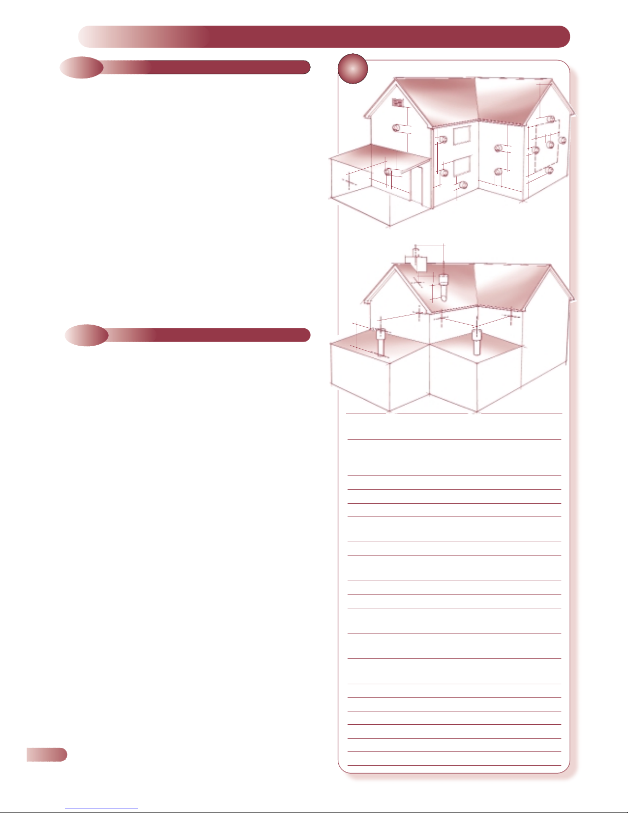
FLUE TERMINAL POSITION
Position Minimum
spacing
A Directly below an openable window, 300mm 12in
air vent, or any other ventilation
opening
B Below gutter, drain/soil pipe 75mm 3in
C Below eaves 200mm 8in
D Below a balcony 200mm 8in
E From vertical drain pipes and 150mm 6in
soil pipes
F From internal or external corners 300mm 12in
G Above adjacent ground or
balcony level 300mm 12in
H From a surface facing the terminal 600mm 24in
I Facing terminals 1200mm 48in
J From opening (door/window) in 1200mm 48in
carport into dwelling
K Vertically from a terminal on the 1500mm 60in
same wall
L Horizontally from a terminal on the 300mm 12in
same wall
M Adjacent to opening 300mm 12in
N Below carport 600mm 24in
O From adjacent wall 300mm 12in
P From adjacent opening window 1000mm 40in
Q From another terminal 600mm 24in
R Minimum height 300mm 12in
GAS SAFETY (INSTALLATION AND USE) REGULATIONS (CURRENT EDITION)
•
A
•
•
G
•
•
D,N
•
•
H,I
•
•
F
•
•
•
J
•
•
B,C
•
•
K
•
•
M
•
•
E
•
•
A
•
•
G
•
•
B,C
•
•
K
•
•
F
•
•
F
•
•
C
•
•
K
•
•
K
•
•
G
•
•
L
•
•
L
•
•
P
•
•
300mm
MIN.
•
•
•
•
Q
•
•
R
•
O
430 mm
MIN.
•
•
O
SPECIAL REQUIREMENTS FOR A
VERTICALLY BALANCED FLUE

3.3
FLUE TERMINAL POSITION
Detailed recommendations for flue installation are given in
BS 5440:1. The following notes are for general guidance.
a) The boiler MUST be installed so that the terminal is exposed to
the external air.
b) It is important that the position of the terminal allows free
passage of air across it at all times.
c) It is ESSENTIAL TO ENSURE that products of combustion
discharging from the terminal cannot re-enter the building, or
any other adjacent building, through ventilators, windows,
doors, other sources of natural air infiltration, or forced
ventilation / air conditioning.
d) The minimum acceptable dimensions from the terminal to
obstructions and ventilation openings are specified in Fig.12.
e) If the terminal discharges into a pathway or passageway
check that combustion products will not cause nuisance and
that the terminal will not obstruct the passageway.
f) Where the lowest part of the terminal is fitted less than 2m
(78ins) above ground, above a balcony or above a flat roof
to which people have access, the terminal MUST be protected
by a purpose designed guard. (Available as an optional extra)
h) The air inlet / flue outlet duct MUST NOT be closer than
25mm (1in) to combustible material.
i) In certain weather conditions the terminal may emit a plume of
steam. This is normal but positions where this would cause a
nuisance should be avoided.
Detailed recommendations for air supply are given in BS 5440:2.
The following notes are for general guidance.
a) It is not necessary to have a purpose provided air vent in the
room or internal space in which the appliance is installed.
b) If the boiler is to be installed in a wall cupboard permanent air
vents are required for cooling purposes in the cupboard at both
high and low levels. Both air vents must communicate with either
the same internal room / space or be on the same wall to
external air. Each air vent communicating with another room or
internal space must have a minimum effective area of:
Ace - 300cm
2
(46.5in2)
Ace High - 337cm
2
(52.in2)
If the ventilation is direct to air from outside the building,
the necessary areas quoted above may be halved.
If the cupboard or compartment is full room height (2.3 m
min.) then NO purpose made ventilation is required.
3.5
GAS SUPPLY
a) The Gas Supplier should be consulted at the installation
planning stage in order to establish the availability of an
adequate supply of gas.
b) An existing service pipe MUST NOT be used without prior
consultation with the Gas Supplier.
c) A gas meter can only be connected by the Gas Supplier or by
their contractor.
d) An existing meter and/or pipework should be of sufficient
size to carry the maximum boiler input plus the demand of
any other installed appliance. (BS 6891: 1988). A
minimum of 22mm dia. pipework is required to
within 1 metre of the appliance gas cock.
e) The governor at the meter must give a constant outlet pressure
of 20mbar (8 in.wg) when all appliance’s on the system are
running.
f) The gas supply line should be purged. WARNING: Before
purging open all doors and windows, also extinguish any
cigarettes, pipes, and any other naked lights.
g) The complete installation must be tested for gas soundness .
3.6
CENTRAL HEATING SYSTEMS
a) This appliance is designed for connection to sealed central
heating water systems. Refer to Fig. 15 for a typical system
design.
b) A sealed system must only be filled by a competent person.
c) The available pump head is given in Fig. 13.
d) A minimum heating flow rate corresponding to a heating
differential of 15°C must be obtained at all times.
e) An automatic heating bypass is fitted within the appliance.
However if thermostatic radiator valves are fitted, a radiator
must be fitted with two lockshield valves.
f) The following paragraphs outline the specifications of the
items fitted to the boiler.
PUMP
The available head shown in Fig. 13 is that in excess of the
appliance hydraulic resistance, i.e. that available for the system.
13
AVAILABLE PUMP HEAD
3.4
VENTILATION REQUIREMENTS
0 2 4 6 8 101214161820 22
7
6
5
4
3
2
1
Flow Rate ltr/min
Available Head Metres
2m HEAD
Ace Ace High
Bth/hr. Kw Flow rate ∆t°C Flow rate ∆t°C
82,000 24.00 17.5l/m 20.0 19.5l/m 17.7
72,000 21.00 17.5l/m 17.7 19.5l/m 15.5
65,000 19.00 17.5l/m 15.5 19.5l/m 14.6
61,500 18.00 17.5l/m 13.3 19.5l/m 13.8
30,700 9.00 17.5l/m 7.5
9

10
EXPANSION VESSEL
The table below shows the maximum system volume that the
integral expansion vessel can sustain under different charge
pressure conditions (pre-charged to 0.75 bar). If the system
volume exceeds that shown, an additional expansion vessel must
be fitted and connected to the heating system primary return pipe
as close as possible to the appliance. If an extra vessel is
required, ensure that the total capacity of both vessels is
adequate. Further details are available in the current issues of
BS5449 and BS6798.
NOTE: If the pressure gauge indicates 2.65 bar or greater when the
appliance is at maximum temperature with all radiators in circulation an
extra expansion vessel is required.
PRESSURE GAUGE A pressure gauge is situated on the
appliance control panel.
PRESSURE RELIEF VALVE A pressure relief valve set at 3 bar
(43.5 psi) is supplied with the appliance.
a) Check that the mains water pressure is sufficient (as stated in
2.4 “General Specification”) to produce the required DHW
flow rate, but does not exceed the maximum DHW pressure
(10 bar). If necessary, a pressure reducing valve must be
fitted to the mains supply before the DHW inlet connection.
b) The final 600mm (24in) of the mains supply pipe to the boiler
must be copper.
c) Avoid long DHW pipe runs and several hot water draw off
points
d) Insulate the Hot water pipes if accessible to minimise the heat
losses within the pipes to keep the water hot longer.
e) A domestic hot water regulator is fitted within the group set to
control the maximum water flow rate. This may be removed to
obtain higher flow rates. Higher flow rates will not damage
the appliance but may reduce the water temperature below an
acceptable level.
f) If the appliance is installed in an area where the temporary
hardness of the water supply is high, say over 150ppm, the
fitting of an in-line scale inhibitor may be an advantage.
Consult the Local Water Supplier if in doubt.
g) For specific information relating to fittings (eg. Showers,
Washing Machines etc) suitable for connection in the DHW
circuit, consult the Local Water Supplier. However the
following information is given for guidance:
DOMESTIC HOT/COLD WATER SUPPLY TAPS AND
MIXING TAPS. All equipment designed for use at mains
water pressure is suitable.
SHOWERS & BIDETS. Any mains pressure shower or bidet
complying with the Local Water Undertaking bylaws is suitable.
h) Consider IRN 116 and Byelaw 90 + 91. Ensure that
necessary action have been carried out to account for thermal
expansion of water. If thermal expansion is not provided then
high water pressure may result in damaging to fittings and
devices.
a) Wiring external to the appliance must be in accordance with
the current l.E.E. Wiring Regulations (BS 7671) for electrical
installation and any local regulations which apply.
b) The mains cable must be at least 0.75mm
2
(24/0.2mm)
PVC Insulated to BS6500 table 16.
c) THIS APPLIANCE MUST BE EARTHED. (Failure to provide
a satisfactory Earth connection will result in appliance
malfunction)
d) The method of connection to the mains supply must facilitate
complete electrical isolation of the appliance. Either a 3A
Fused three pin plug and unswitched shuttered socket outlet,
both complying with BS1363, or a 3A fused double pole
switch having a 3mm contact separation in both poles and
serving only the boiler (and its external controls) may be used.
The appliance may be used with any Certificated mains voltage
room thermostat and/or single channel programmer as described
in section 4.8.
3.7
DOMESTIC HOT WATER SYSTEM
3.8
ELECTRICITY SUPPLY
3.9
EXTERNAL CONTROLS
EXPANSION VESSEL REQUIREMENTS
Vessel charge and initial
system pressure
Total water content of system
using 8ltr. (1.54gal) capacity expansion
vessel supplied with appliance
For systems having a larger
capacity multiply the total system capacity
in litres (gallons) by the factor to obtain the
total minimum expansion vessel capacity required litres (gallons)
bar 0.5 0.75 1.0 1.5
psi 7.3 11 14.5 21.8
96ltr 84ltr 73ltr 50ltr
21gal 18gal 16gal 11gal
0.0833 0.093 0.109 0.156
14
ALTERNATIVE METHODS OF FILLING A SEALED SYSTEM
•
MAINS WATER
SUPPLY
•
•
•
DOUBLE
CHECK
VAL VE
ASSEMBLY
•
STOP
VAL VE
•
STOP
VAL VE
•
HEATING SYSTEM
RETURN
•
CISTERN &
OVERFLOW
•
MAINS
WATER SUPPLY
•
PRESSURE PUMP
& REDUCING VALVE
IF REQUIRED
•
STOP
VAL VE
•
HEATING
SYSTEM
RETURN
FLEXIBLE HOSE UNION
TEMPORARY CONNECTION
To be removed immediately after filling
RECOMMENDED AND APPROVED METHOD FOR
FILLING A CLOSED CIRCUIT IN A HOUSE.
(R24-2a WATER REGULATIONS GUIDE)

15
TYPICAL SYSTEM DESIGN
Note: The boiler incorporates an automatic bypass, hence no other
system bypass is necessary. However, it is recommended to fit TRV’s on
all radiators except in rooms with a room thermostat.
If no room thermostat is fitted, at least one radiator (preferable in the
bathroom) must be permanently open, i.e. fitted with two lockshield
valves.
•
APPLIANCE
•
CH FLOW
•
•
DOMESTIC HOT
WATER OUT
•
GAS SUPPLY
•
MAINS IN
•
CH RETURN
•
RADIATOR WITH
2 LOCKSHIELD VALVES
IN OPEN POSITION
PRESSURE RELIEF VALVE
OUTLET TO DRAIN
•
DOMESTIC HOT
WATER
•
DOMESTIC COLD
WATER
•
PRESSURE REDUCING
VALVE IF REQUIRED
•
BS STOP VALVE
(FIXED SPINDLE)
•
MAINS WATER
•
DRAIN COCK
AT LOWEST POINT(S)
OF SYSTEM
11
INSTALLING THE APPLIANCE
4
17
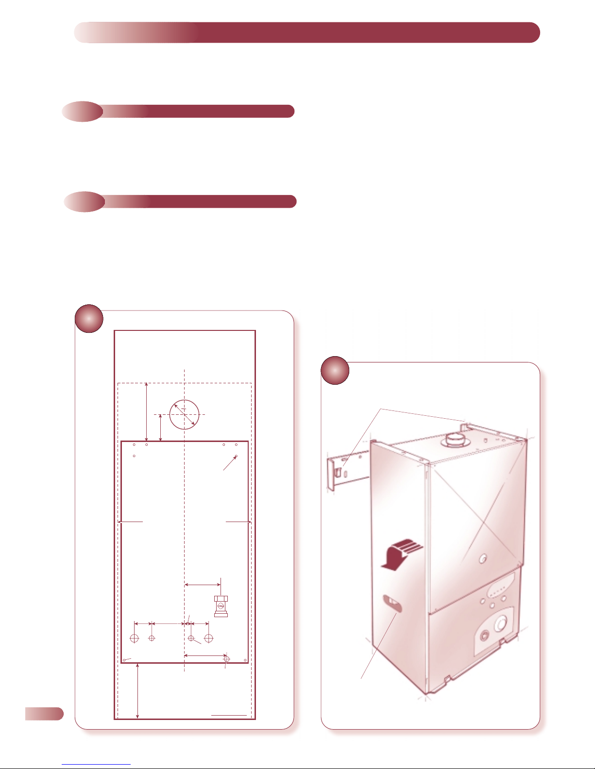
MOUNTING THE BOILER
16
PAPER TEMPLATE
Before installing the appliance, check that the chosen location is
suitable (section 3.2), and that the requirements for flue position
(section 3.3), and minimum clearances (Fig. 1b) are satisfied.
a) Fix the paper template in the required position (ensuring that
the necessary clearances are achieved) and mark the position
of the fixing holes as shown in Fig. 16. Three holes are
provided at each side of the wall bracket.
4.2
PREPARING THE WALL
4.1
UNPACKING THE APPLIANCE
The appliance and standard flue kit are supplied in a single box.
In addition, various optional flue kits are available as described in
section 2.6. If the appliance is to be installed without access to an
external wall, a wall liner kit is also required.
LOCATING TABS
LIFTING POINT
•
•
•
Mark the position of the flue outlet as described in Fig. 18.
Mark the position of pressure relief outlet if required and the
water and gas connections. Remove the paper template and
proceed as follows.
b) Cut the hole in the wall for the air/flue duct. The diameter
must not be less than 100mm and the hole must be horizontal.
If the hole is not accessible from outside, it’s minimum
diameter must be sufficient to allow insertion of the wall liner
(130mm, 5
1
/4in). The wall liner is available as an optional
extra and must be sealed in position with mortar (or
equivalent). It is recommended that the flue assembly falls
slightly downwards away from the boiler.
c) Drill two fixing holes using a 8mm drill and insert the wall
plugs provided in the hardware pack. If any of the holes fail
to provide a secure fixing, use one of the adjacent holes
instead.
d) Fix the bracket into position and secure to the wall using the
two screws provided. Ensure it is level.
94
FLUE
0 100
WALL FIXING HOLES
WALL FIXING HOLES
5 SIDE CLEARANCE 5 SIDE CLEARANCE
65 115
130
18.5
65
146
PRESSURE
RELIEF
CH FLOW
GAS INLET
1/2" BSP
DHW HOT OUTLET
COLD
INLET
CH
RETURN
200 CLEARANCE
ABOVE CASE
200 CLEARANCE
BELOW CASE
CENTRE LINE OF BOILER
12

13
18
DETERMINING THE POSITION OF THE
AIR/FLUE DUCT HOLE
19
a) Commission the central heating system as described in section
5.1, then proceed to section 4.5.
a) Use a 15mm copper tube or bend to connect to the gas
service cock to a 15mm compression fitting.
a) Lift the boiler into position using the lifting points shown in
Fig. 17. Position the top of the boiler approximately 10mm
above the top of the wall bracket and use the tabs on the wall
bracket to locate the boiler in a horizontal direction, then
carefully lower the boiler ensuring the two locating tabs are
securely engaged (see Fig. 17).
b) Locate and tighten the water and gas valves to the boiler.
(Seals are pre-fitted).
c) Connect the central heating system to the boiler flow and
return using the connections shown in Fig. 19.
d) Connect the mains water supply and outlet to the appropriate
connections as shown in Fig. 19.
4.4
SERVICE CONNECTIONS
4.3
MOUNTING THE BOILER
4.5
GAS CONNECTION
•
PRESSURE
RELIEF
45mm
SERVICE CONNECTIONS (rear view)
a) Connect a suitable discharge pipe to the pressure relief valve
tube. The pipe should be a minimum diameter of 15mm
copper and should avoid any sharp corners or upward pipe
runs where water may be retained. The discharge pipe must
terminate in an area where any discharge will not cause a
hazard but will be noticed.
4.6
PRESSURE RELIEF VALVE
PIPE CONNECTION
•
CENTRAL
HEATING
FLOW
•
DOMESTIC
HOT WATER
OUT
•
GAS COCK
•
MAINS
COLD
WATER IN
•
CENTRAL
HEATING
RETURN
65mm
65mm
133mm
63mm
78mm
18(b) SIDE FLUE
18(a) REAR FLUE
POSITION OF
DUCT HOLE
•
•
POSITION OF
WALLPLATE
•
•
94mm
227.5mm
227.5mm
188mm
94mm

4.7
AIR/FLUE DUCT INSTALLATION
4.7.1
PREPARING THE AIR/FLUE DUCTS
20
MEASURING THE EXACT FLUE LENGTH
21
AIR/FLUE DUCT ASSEMBLY
If the wall thickness is less than 800mm (31 in) the air/flue duct
may be fitted without access to the external wall providing that the
optional wall liner is used. (This is necessary to seal any cavity
and to allow the sealing ring to pass through from inside but still
open and provide an adequate seal). The wall liner is a tube
diameter 130mm with a wall thickness of 0.8mm.
a) Measure the required flue length as shown in Figure 20. Refer
to section 2.6 to determine whether any extension kits are
required. Installations using only the standard ducts or standard
ducts with straight extensions are described in this section.
Installation instructions for all other flue systems are described
in the supplements at the rear of this booklet.
b) Fit the external sealing ring to the terminal assembly and
assemble the air/flue ducts as shown in Figure 21. The
standard duct is always used at the entry / exit to the boiler,
and the sliding (telescopic) terminal is always slid into the end
of the standard or extension duct (where appropriate).
c) Achieve the correct flue length using Figure 22 as a guide.
Note that the flue length is measured to the inside of the
external wall sealing ring. In most cases it will be possible to
achieve the required flue length without cutting the ducts,
however where necessary the plain ends of the extension ducts
may be cut. Never cut the swaged end, and always
ensure that the cut is square and free of burrs or debris. The
minimum overlap of the telescopic section is 50mm (2 in).
d) Assemble the flue using Figure 23 as a guide. It is important
that the steps are carried out in the order stated in Figure 23.
When securing the ducts in position always drill two 3.3 mm
diameter holes in each extension air duct joint and use the self
tapping screws provided to secure each joint.
NOTE IT IS ESSENTIAL THAT THE TERMINAL IS FITTED THE
CORRECT WAY UP See Fig 21 (i.e. rainshield at the top).
•
•
STANDARD DUCT
Fits Outside Elbow
•
EXTENSION DUCT(S)
Fits Over Duct
•
STANDARD
TERMINAL
Fits Inside Duct
•
EXTERNAL SEALING
RING
•
TOP
FAN OUTLET
EXTERNAL
Dia. 60mm
•
TOTAL FLUE LENGTH FROM
FLUE OUTLET CENTRE TO
OUTSIDE WALL FACE:
= LENGTH
L
WALL
L
•
•
•
•
Ensure the “O” ring
(fitted in the flanged
end of the flue elbow
only) is located correctly.
14

15
22
ACHIEVING THE CORRECT FLUE LENGTH
23
ASSEMBLING THE FLUE SYSTEM
•
•
•
INSIDE EDGE OF
EXTERNAL SEAL IN
POSITION ON AIR
DUCT
•
•
•
•
•
•
•
•
767mm
EXTENSION
MIN. OVERLAP
50mm (2in)
425mm
L
76mm
MAX. 319mm
•
TOP
•
•
•
•
1 SLIDE EXTERNAL SEALING RING UPTO FLUE TERMINAL
L
2
STANDARD DUCT
Push ducts fully over elbow
and drill two 3·3mm dia.
holes. Secure with self
tapping screws
•
•
•
•
3 EXTENSION
Push extension duct
(if required) over standard
duct, engage fully.
Drill two 3·3mm dia. holes
and secure with
self-tapping screws
6
Drill and screw
telescopic
overlap
5 STANDARD
TERMINAL
Slide telescopic
section to achieve
length ‘L’
4
Check terminal
is correctly
aligned
(see Fig. 27)
•
INTERNAL
SEALING
RING
•
•
17mm

24
25
•
FITTING THE FLUE RESTRICTOR
•
FLUE RESTRICTOR
•
APPLIANCE TOP
FLUE RESTRICTOR LOCATION
(Do not disturb if extension ducts are to be fitted)
90° ELBOW
ALUMINIUM
FAN OUTLET
RESTRICTOR
•
•
•
16
4.7.2
FLUE RESTRICTOR
A flue restrictor is supplied with the appliance for use, only
if no extensions or additional flue extension elbows are
fitted.
If any extension ducts or additional elbows etc are to be used,
proceed to section 4.7.3.
If only the standard flue components (i.e. those packed in the same
carton as the appliance) are to be used fit the restrictor as follows:
a)) Note the position of the flue restrictor ring. This is fitted on top
of the appliance and is secured by the air pressure switch
bracket screws (Fig. 24). Loosen the air pressure switch screw
by 1/2 turn only, to release the ring, and tighten the two screws.
b) Fit the restrictor ring inside the flue elbow bottom as shown in
figure 25 ensuring that it is the correct way round.
NOTES
(i) Failing to fit the restrictor when installing the appliance with a
standard flue system will not provide optimum appliance performance.
(iii)Fitting the restrictor on a flue system incorporating extensions
or additional bends will adversely affect performance and
TOP
4.7.3
INSTALLING THE AIR/FLUE DUCT
FROM INSIDE THE ROOM
Wall thickness up to 800 mm (31in) only.
a) Push the terminal through the wall liner taking care to ensure that
the terminal is the correct way round and the external wall sealing
ring does not become dislodged.
b) Pull the flue system towards the boiler to seat the external sealing
ring against the outside wall and secure the elbow to the boiler
using the four screws provided.
c) Finally use the internal sealing ring to make good the internal
hole, and check that the terminal is correctly located on the
outside wall (Where possible this should be visually checked
from outside the building).
Figure 26 shows a view of the flue system correctly installed.
d) Assemble as shown in Figure 26.
26
•
•
•
•
2 ALIGN ASSEMBLED
FLUE SYSTEM ELBOW TO
APPLIANCE AND SECURE
3 SLIDE INTERNAL
WALL SEALING RING TO
WALL TO FORM
A GOOD SEAL
1 INSERT
ASSEMBLED FLUE
SYSTEM FROM
INSIDE THE ROOM.
EXTERNAL WALL
SEALING RING
OPENS
•
EXTERNAL
WALL
SEALING
RING
130mm Dia.
HOLE WITH
WALL LINER
INTERNAL WALL
SEALING RING
TOP
•
FIBRE
SEAL FITTED
INSTALLING THE FLUE SYSTEM FROM
INSIDE THE ROOM
may constitute a safety hazard.
(iii)Failing to comply with these instructions will invaildate the
appliance Certification and therefore may contravene the
appropriate EC legislation and local statutory requirements..

28
ELECTRICAL CONNECTIONS (rear view)
27
INSTALLING THE FLUE SYSTEM FROM OUTSIDE THE BUILDING
4.8
WIRING INSTRUCTIONS
Connect the electricy supply and external controls (using suitable
mains cable) as follows:
Wire the cable(s) into the appropriate connections in the electrical
plug provided (Figure 28). Live supply to L2, Neutral and Earth as
indicated. Check that L1 and L3 are linked.
To provide correct cable retention, fit the piece of tubing supplied
over the cable as it passes through the clamping arrangement. The
cable will be held in position as the plug cover is fitted.
If a room thermostat is to be fitted remove the red link between L1
and L3 and connect the thermostat across these terminals. Any
external controls fitted must be rated at 230V 50Hz and have voltfree contacts.
NOTE: Assuming that the appliance is to be
commissioned immediately after installation it is not
necessary to fit the casing panels at this stage.
•
•
•
•
•
4 REFIT AND SECURE
ELBOW TO AIR DUCT,
THEN TO APPLIANCE
1 FIT ELBOW
(AFTER SETTING CORRECT
LENGTH AND ALIGNMENT)
3 SLIDE INTERNAL
WALL SEALING RING
OVER AIRDUCT. PUSH
AGAINST THE WALL TO
FORM A GOOD SEAL
2 INSERT FLUE
LENGTHS FROM
OUTSIDE THE
ROOM. ENSURE
EXTERNAL WALL
SEALING RING
FORMS A GOOD
SEAL
•
EXTERNAL
WALL
SEALING
RING
TOP
100mm
Dia. HOLE
INTERNAL WALL
SEALING RING
•
FIBRE SEAL FITTED
(Flue hole diameter 100mm - wall liner not necessary)
a) Secure the flue elbow with seals and flue adaptor (where
necessary) to the appliance using the 4 screws provided.
b) Fit external wall sealing ring over flue and then from outside
the building, push the flue system through the wall taking care
to ensure that the terminal is the correct way around.
c) Fit the internal wall sealing ring over the inside end of the flue,
then fit the air duct to the elbow, drill and secure with the two
screws.
d) Pull the flue system towards the boiler to seat the external
sealing ring against the outside wall and secure the air duct to
the elbow using the two screws provided.
e) Finally use the internal sealing ring to make good the internal
hole. Check that the external wall sealing ring is correctly
located, on the outside wall from outside the building.
Figure 27 shows a view of the flue system, correctly installed.
4.7.4
INSTALLING THE AIR/FLUE DUCT
FROM OUTSIDE THE BUILDING
17
Note: If room thermostat is to
be fitted remove the link and
connect room thermostat
across L1 and L3.

18
Note: It is recommended, where possible, to flush the CH system without the boiler fitted, to avoid debris
and flux blocking the plate heat exchanger.
1 Check that the CH flow and return valves are in the open position.
2 Fill the system with water using one of the approved methods described in section 3.6 to about 2.0 bar. Vent the system via the
radiator valves and system air vents in accordance with normal practice. Ensure that all system air vents are closed.
3 Check the system for soundness.
4 Check the operation of the pressure relief valve (Fig. 32) by rotating the plastic head anticlockwise 1/4 of a turn and checking
that water is discharged. Ensure that the valve seats correctly and does not leak. If the valve leaks or is stuck closed, replace
it..
5 Drain the entire system to flush out any debris, and refill to 0.2 bar above the system design pressure (between 0.5 and 1.5
bar) by repeating the above procedure. Follow the commissioning procedure described below, then repeat this instruction with
the system hot. It is recommended that the system is cleaned with a recognised system cleaner such as Fernox or Sentinel.
6 Open the DHW inlet valve and open and close each hot water tap in turn to clear all the air from the pipes and the boiler.
7 Remove the pump end cap and rotate the rotor, replace the cap.
8 If filling loop is used, disconnect filling loop.
9 Prior to firing up the boiler to check the gas rates, the Central Heating and Boiler system should be checked for circulation by
running the boiler and pump with gas turned off, to ensure no air locks occur.
COMMISSIONING AND TESTING
5
5.1
FILLING THE WATER SYSTEMS
29
Before commissioning the appliance, the whole gas installation
including the meter MUST be purged and tested for gas soundness
in accordance with BS 6891:1988.
IMPORTANT: Open all doors and windows, extinguish
naked lights, and DO NOT SMOKE whilst purging the gas
line.
Before commencing the commissioning procedure, ensure that the
gas service cock is turned on, the electricity supply is isolated, and
that the DHW and CH pipe work is complete.
Fill the water systems by following the procedure detailed below
Fig 29, steps 1 to 9.
VALVE POSITIONS FOR COMMISSIONING THE
WATER SYSTEM
(rear view)
•
PRESSURE
RELIEF
•
CENTRAL
HEATING
FLOW
•
DOMESTIC
HOT WATER
OUT
•
GAS COCK
•
MAINS
COLD
WATER IN
CENTRAL
HEATING
RETURN
•

5.2
COMMISSIONING THE APPLIANCE
a) Loosen the screw and connect a manometer to the burner
pressure test point on the gas valve (Fig. 35).
b) Turn the hot water control (Fig. 30) to maximum (fully
clockwise). Turn on the electrical supply and select the Hot
Water position on the Main Switch – the Power On LED will
be illuminated.
c) Fully open any DHW tap and the ignition sequence will
commence. The Hot Water and the Burner On LEDs will be
illuminated. If the burner fails to light, ignition lock-out occurs.
In the event of ignition Lock-out the safety Lock-out LED will be
illuminated. To re-set the appliance and initiate a further
ignition attempt it is necessary to turn the Main Switch through
to the Reset position (spring return).
d) After ignition, allow the boiler to run for at least 10 minutes
and check that the burner pressure is as stated on the data
badge ±10%. The DHW burner pressure is factory set and
should not require adjusting. If the burner pressure is low,
check that the appliance has not started to modulate (This will
occur if the DHW flow rate is low. If modulation is suspected,
open all DHW taps to maximise flow and re-check burner
pressure) If it is necessary to adjust the DHW burner pressure
the method is described in section 9.6 Gas valve replacement.
e) Close the DHW tap and ensure that the Burner On LED (Fig. 30)
goes off, the burner goes out, and the pump stops after an
overrun period.
f) Ensure that the room thermostat (if fitted) is calling for heat. Turn
the Main Switch to Heating & Water and turn the heating
control knob (Fig. 30) to maximum (fully clockwise), and finally
turn the clock override switch (Fig. 30) to the I position. The
burner will light at an ignition gas rate of approx. 5 mbar. After
ignition the burner pressure drops to approx. 1.3 mbar and
over a period of time the heating load will ramp up to factory
set burner pressure.
NOTE: that the central heating burner pressure is
factory set to 6.3 mbar (app. 19.5kW or 66,000 Btu/h,
gross heat input) and should not require adjusting. If it
is necessary to adjust the CH burner pressure the
method is described in section 9.9.1 Gas valve
replacement.
g) Set the clock to the desired times by setting the tabs.
h) Slide the clock override switch to the 'timed' position and
check the operation of the clock and room thermostat (If fitted).
30
FASCIA PANEL AND CONTROLS
19
•
ARROW
INDICATES
CURRENT TIME
•
CLOCK OVERRIDE
= Continuous ON
= Timed
= OFF
•
TABS OUT
= ON PERIOD
•
TABS IN
= OFF PERIOD

20
5.3
DOMESTIC HOT WATER FLOWRATE
5.4
FINAL CHECKS
31
FITTING THE CASING PANELS
5.7
FROST PROTECTION
5.8
OTHER FEATURES
5.9
USERS INSTRUCTIONS
A flow regulator is supplied factory fitted to the appliance to ensure
that no adjustment is necessary. Should the mains flow rate be below
the minimum required it is possible to remove the flow regulator from
the appliance as instructed in section 9 (Fig. 37).The nominal preadjusted flow rate may vary by ± 5% due to factory tolerances and
mains water pressure fluctuation.
a) Turn the appliance off and remove the manometer and tighten
the burner pressure test point screw. Re-light burner and test for
gas soundness.
b) Fit the boiler casing as described and illustrated in Figure 31: Fit
each side panel (both are identical) with two screws at the top
and bottom of each panel. Fit the front panel in position and
locate by gently sliding it downwards over the supporting tabs.
Screw into position using the single fixing screw at the top of the
casing.
c) Set the heating and hot water controls (Fig. 30) to the required
settings. Ensure that the clock override switch is in the timed
position, and check that the time clock is set at the desired time
periods. Set the room thermostat (if fitted) to the required setting.
This appliance is fitted with an overheat thermostat. In the event of
overheating, the appliance will shut down and the safety lockout
LED will light. If an overheat condition occurs, allow the appliance
to cool, then press the overheat reset button once (located
underneath the appliance at the left hand side). The Ignition safety
lockout LED will also be illuminated and require re-setting. To re-set,
turn the main switch through to the Reset position (spring return).
5.5
IGNITION LOCKOUT
5.6
OVERHEAT THERMOSTAT
In the event of an ignition failure, the safety lockout LED will be
illuminated. To re-set, turn the main switch through to the Reset
position (spring return).
This appliance is fitted with a frost protection device. In the event of
very cold conditions the pump may operate and the boiler may light
for a few minutes to protect the appliance and system from potential
frost damage. This can only function if the gas and electricity
supplies are maintained and the main switch on the appliance is left
either in the Hot Water or Heating & Water mode. The clock can be
switched to the off setting.
The following additional features are included in the appliance
specification:
ANTI-CYCLE DEVICE: When the appliance cycles on it’s central
heating control setting, a slow cycle device operates. The timer (set to
3 mins) is activated after the end of burn cycle to prevent rapid cycling
of the burner.
ANTI PUMP SEIZURE DEVICE:
Providing that a power supply is maintained and the Main Switch is
either in the Hot Water or Heating & Water mode, the pump will
operate for at least 20 seconds every 23 hours (regardless of heat
demand) to prevent pump seizure during periods where the appliance
is not used.
WATER FLOW SWITCH:
This device prevents the burner from firing if there is inadequate water
flow through the main heat exchanger.
Upon completion of commissioning and testing the system, the
installer should draw the user's attention to the following.
a) Give the 'Users Instructions' to the householder and emphasise
their responsibilities under the 'Gas Safety (Installation and Use)
Regulations 1996' (as amended).
a) Explain and demonstrate the lighting and shutdown procedures.
b) Advise the householder on the efficient use of the system,
including the use and adjustment of all system controls for both
DHW and CH.
c) Advise the user of the precautions necessary to prevent damage
to the system, and to the building, in the event of the system
remaining inoperative during frost conditions.
d) Explain the function of the boiler overheat thermostat, and how
to re-set it. Emphasise that if cut-out persists, the boiler should be
turned off and the installer or service engineer consulted.
e) Stress the importance of an annual service by a registered
heating engineer.
f) The electrical mains supply to the appliance must remain ON
and the Main Switch must left either in the Hot Water or
Heating & Water mode for the frost protection circuit to
operate.
5.10
BOILER LOGBOOK
A logbook is supplied with this appliance to record installation and
commissioning details and make future servicing of the appliance
easier.
This logbook forms part of the industry's Benchmark code of practice
for the installation, commissioning and servicing of central heating
systems.
Please ensure that the logbook is fully completed and left with the
customer for future reference along with Users Instructions and this
Installation and Servicing Instruction manual.

ROUTINE SERVICING
6
32
LOCATION OF
SERVICEABLE
COMPONENTS
6.1
MAIN BURNER ASSEMBLY
6.2
BURNER INJECTOR
6.3
IGNITION AND DETECTION ELECTRODES
To ensure continued efficient operation of the appliance, it is
recommended that it is checked and serviced as necessary at
regular intervals. The frequency of servicing will depend upon the
particular installation conditions and usage but in general once a
year should be adequate. It is the law that any service work must
be carried out by a competent person, such as British Gas or
other CORGI registered personnel.
The boiler incorporates a flue sampling point on the top panel in
front of the flue outlet. If the service engineer has suitable
equipment to analyse the flue gas, the plastic cap may be
removed and a 6mm inside diameter sample tube fitted. Do not
forget to replace the plastic cap after use.
Before commencing any service operation, ISOLATE the mains
electrical supply, and TURN OFF the gas supply at the main
service cock.
Service the appliance by following the full procedure detailed
below:
a) Remove the casing front panel by unscrewing the panel
retaining screw and lifting off the panel.
b) Remove the sealed chamber front panel (4 screws).
c) Remove the combustion chamber front panel (7 screws). Take
care not to damage the insulation.
Do not attempt to light the burner with Front Panel
removed.
d) Remove the 4 screws securing the burner on the gas manifold.
e) Unscrew and remove the two screws securing the control
panel in the upright position and pivot the panel forwards.
f) Remove the two spark and one detection electrode leads from
the electrodes.
Check that the injectors fitted in the gas manifold are free from dirt
and debris. If necessary clean the injector orifice carefully using a
soft brush or vacuum cleaner. Do not use a wire brush or any
abrasive material.
It is not necessary to remove the injectors. If there are
signs of injector(s) being blocked please call the Halstead Service
Department.
a) Inspect the ignition and detection electrodes in situ. If
necessary clean using a soft brush. If either the electrode or
the ceramic insulation show signs of damage or wear, replace
the electrode(s).
b) Check that the alignment of the ignition and detection
electrodes are as shown in Figure 34. Adjust by carefully
bending the tip of the electrode rod whilst supporting the base
of the rod. Do not put any pressure on the ceramic insulation.
g) Remove the burner by lifting it forward with reference to
Figure 33.
h) Inspect and if necessary clean the main burner ports using a
soft brush or vacuum cleaner. Do not use a wire brush or any
abrasive material.
•
COMBUSTION CHAMBER
FRONT PANEL FIXING
SCREWS (7)
•
•
•
•
•
•
•
•
•
•
•
•
AUTO AIRVENT
FAN ASSEMBLY BASE
PLATE SCREWS
PUMP
GROUP SET
CONTROL
COVER
AIR PRESSURE
SWITCH & PIPES
DETECTION ELECTRODE
BURNER
IGNITION ELECTRODES
•
GAS CONTROL VALVE
•
PRESSURE RELIEF
VAL VE
FAN ASSEMBLY
•
PRESSURE
GAUGE
•
OVERHEAT THERMOSTAT
•
CONTROL PANEL
21

22
33
BURNER REMOVAL
34
ELECTRODE ALIGNMENT
6.5
AIR PRESSURE SWITCH PIPES
6.6
HEAT EXCHANGER
6.7
GENERAL
6.8
RE-ASSEMBLY
6.9
RE-COMMISSIONING
6.10
SEALED WATER SYSTEMS
6.11
FINAL CHECKS
Check that the pressure switch sensing pipes are not blocked or
damaged. It is not necessary to remove the air pressure switch,
this is not adjustable and does not require any servicing.
a) Inspect the heat exchanger from both above and below the
fins. If necessary, clean the fins with a soft, non metallic brush.
a) Check that the combustion chamber insulation is not
damaged.
b) Clean the inside of the sealed chamber using a soft brush or
(preferably) a vacuum cleaner.
c) Check that the sealed chamber front panel seal is intact and in
good condition. Replace if necessary.
d)
Always wear a protective mask when cleaning the
appliance.
Re-assemble all components in reverse order except do not pivot
the fascia panel back into position or fit the casing front panel
until the servicing work has been completed.
When re-fitting the burner it is essential to ensure that the burner is
level as shown in Figure 33 and that it is correctly assembled into
the injector.
Check that all joints and seals are correctly fitted. Note that fan
polarity is immaterial.
a) Loosen the screw at the burner pressure test point and connect a
pressure gauge to this point (Fig. 35). Turn on the gas and
electricity supply and light the boiler as described in section 5.2
b) Check the operation of the appliance in both central heating
and DHW modes and ensure that the DHW maximum and
minimum burner pressures after ten minutes running are as stated
on the data badge.
c) Remove the pressure gauge and tighten the sealing screw.
Re-light the appliance and test for gas soundness.
a) Carefully disconnect the tab connectors on the fan wiring from
the fan.
b) Disconnect the air pressure switch sensing pipes from the fan,
noting their positions
c) Remove the fan assembly by unscrewing the two screws,
lowering the assembly and lifting it forwards.
d) Inspect the fan assembly (especially the impeller and the
venturi) for dirt, damage, or signs of wear. If necessary clean
the impeller or/and venturi using a soft brush or vacuum
cleaner. Spin the impeller and check that it rotates freely,
without noise, and without imbalance. If there is any sign of
deterioration or damage, replace the fan.
a) Check the operation of the pressure relief valve as described
in section 5.1.
b) Check the correct operation of the pressure gauge by noting
the reading when cold and check that the pressure increases
with temperature. Replace the gauge if readings are suspect.
c) Check that the system is at it's original (cold) design pressure
(indicated by the pointer on the pressure gauge). If necessary,
re-pressurise the system as described in section 5.1 and
search for and rectify any leaks causing loss of water.
a) Pivot the fascia panel into the upright position and secure with
the two screws, then re-fit the front casing panel (Fig. 31).
b) Return all appliance and external controls (if fitted) to their
original settings.
IGNITION ELECTRODE
DETECTION ELECTRODE
(flame sensor)
6.4
FAN ASSEMBLY
12.2
20.0
2.5 ± 0.5
•
•
•

INTERNAL WIRING DIAGRAMS
7
7.1 : FUNCTIONAL FLOW WIRING DIAGRAM
23

7.2 : ILLUSTRATED WIRING DIAGRAM
24

25
FAULT FINDING
8
8.1
GENERAL
8.2
DIAGNOSTIC INDICATOR LED’S
8.3
IGNITION FAULTS
8.4
DHW FAULT FINDING
8.5
CENTRAL HEATING FAULT FINDING
Before looking for a fault condition, check that:
The mains electrical supply is turned on.
The clock and / or room thermostat (if fitted) are calling for heat
(CH 'faults' only)
The gas service cock is open.
The DHW and CH isolation cocks are open.
The system is at design pressure.
Before attempting any electrical fault finding, always conduct the
preliminary electrical system checks as described in the Instructions
for the British Gas Multimeter or other similar instrument.
On completion of any service or fault finding operation involving
making or breaking electrical connections always check for EARTH
CONTINUITY, POLARITY, and RESISTANCE TO EARTH.
Detailed procedures for replacing faulty components are described
in section 9 (Parts Replacement)
The LEDs on the fascia panel (Fig. 30) show the status of the boiler
as described below:
Power ON LED illuminated. (Green): Boiler is in service. If no
other LEDs are illuminated, the appliance is awaiting a demand for
heating or hot water.
Burner ON LED illuminated (Green): Burner is alight.
Hot Water LED illuminated (Green): Boiler is in DHW mode.
Heating LED illuminated (Green): Boiler is in Heating mode.
Safety Lockout LED illuminated (Red): Burner has failed to light
and gone to ignition lock-out and possibly overheat cut-out. Re-set
the appliance by turning the mains switch through to the Reset
position (spring return) and if necessary, re-set the button on the
overheat thermostat (left hand underside of casing).
NOTE: There may be a fault condition preventing ongoing
operation of the appliance. Follow fault finding procedure.
In the event of the boiler failing to light, investigate the problem by
following the flow chart.
When the hot water tap is turned on, the controls should carry out
a set of start up checks (flow chart 1) followed by an ignition
sequence (flow chart 2)
If the control has powered up correctly but does not respond to a
DHW demand, investigate in the following order:
Check for 0V d.c. across pins 10 and 11 on X4. If 5V is present
across pins 10 and 11 check water flow switch and wiring.
If 0V is present, check DHW thermistor and wiring. If DHW
thermistor and wiring are OK, replace PCB.
If DHW temperature heavily fluctuates during a long draw off
and occasionally goes in an overheat Lock-out condition, check
the secondary plate heat exchanger for debris and replace.
Upon a demand for Central Heating, (closure of the time switch
and room thermostat if fitted) the appliance should respond to the
demand.
If the control does not respond to a CH demand, investigate in the
following order:
If 230 Va.c. is present across pins 1 and 2 on X1 but no start up
procedure occurs ensure that the control is not in anti-cycle mode
by removing power from the control and restoring it after a delay
of 10 seconds, or open a hot water tap for a few seconds.
If the control still does not carry out start up checks, check CH
thermistor (pins 12 and 13 on X4) and wiring.
If CH thermistor and wiring are okay, replace PCB.
NOTE: Whenever a CH demand is removed, either by the
timer, the room thermostat or the boiler internal
temperature control, an anti cycle mode is initiated which
prevents the boiler firing in CH mode for 3 minutes.

26
FLOW CHART 1: START/POWER UP FAULT FINDING
FLOW CHART 2: IGNITION SYSTEM FAULT FINDING
YES YES
Is APS in closed
position
Check overheat thermostat and
RESET if necessary
YES
When fan stops is
red LED (Safety lockout)
illuminating?
YES YES
Replace flow switch
Check water pressure. Switch
mains off to reset flow switch.
Does green LED continue to blink
When fan stops is green
LED (Power ON) blinking?
YESNO YES
Is APS in closed
position?
Is 230V present across
pins 7 and 8 on X6?
Replace
PCB
NO
Start
YES
YES
NO
YES
YES
NO
NO NO
YES
NO
NO
Is 230V present across
pins 1 and 2 on X1
Gain access to boiler
control then switch on
electrical supply
Turn Main Switch to
Heating & Water mode
Is green LED (Power ON)
illuminating?
Activate a heat demand via
Timer/Roomstat or open
a hot water tap
Is the pump running?
Is the fan running?
NO
Replace APS
Re-check main connector at
the back including fused outlet
Check PCB F4 Amp fuse, if
blown replace. If fuse OK
replace board
Check pump rotation
Is 230V present across
pins 1 and 3 on X3?
Replace
PCB
Replace fan
YES
Start
YES
YES
YES
YES
YES
YES
NO
NO
NO
NO
NO
NO
NO
YES
YES
YES
Is green LED (Power ON)
illuminating, primary flow
switch contacts closed?
Replace
flow switch
Turn Mains Switch to
Heating and Water mode
PCB should carry out APS,
pump flow switch and
overheat checks
Is red LED (Safety Lockout)
illuminating?
Are sparks present at
the spark electrode?
Is the burner light and
the green LED (Burner ON)
illuminated?
Does burner remain lit?
Ignition sequence complete
Is green LED (Power ON)
blinking
See Chart 1
Is spark gap distance to
burner as described in Fig. 35?
Re-adjust as necessary
Is 230V DC present across
pins 4 & 3 0n X6
Check polarity, i.e. is Live and
Neutral to boiler crossed
Check Detection electrode.
Replace as necessary
Check water pressure.Switch
mains off to reset flow switch.
Does green LED continue to blink.
Replace PCB
Replace gas valve
Replace PCB
Note: An anti-cycle timer is built into the control system. If the appliance does not light, wait a
minimum of three minutes before restarting the boiler.

27
REPLACEMENT OF PARTS
9
9.1
HEAT EXCHANGER
9.2
COMBUSTION CHAMBER INSULATION
9.3
FAN ASSEMBLY
9.4
BURNER
9.5
IGNITION & DETECTION ELECTRODES
9.6.1
GAS CONTROL REPLACEMENT
a) Remove the casing front panel by unscrewing the retaining
screw (on top of panel) and lifting off the casing panel.
b) Remove the sealed chamber front panel (4 screws).
c) Remove the nut securing the burner to the burner locating
bracket (and burner earth wire).
d) Remove the combustion chamber front panel and burner locating
bracket (7 screws). Take care not to damage the insulation.
e) Unscrew and remove the two screws securing the fascia panel
in the upright position and pivot the control panel forwards.
f) Remove the three electrode leads from the electrodes and
unclip the grommet in the bulkhead below the burner to
release the earth, ignition, and detection wires.
g) Unscrew and remove the four screws securing the burner to
the gas manifold and remove the burner by sliding it forwards
with reference to Figure 33.
h) Turn the CH flow and return valves to the closed position to
isolate the boiler. Drain the appliance.
i) Carefully remove the LH combustion chamber insulation panel,
the clip must first be removed from the rear LH lower corner of
the combustion chamber, to reveal an access hole to the heat
exchanger union connections.
j) Using a suitable spanner, unscrew the heat exchanger
connections from inside the combustion chamber.
k) Lift the heat exchanger clear of the two pipes, then remove the
heat exchanger by sliding it forwards.
l) Replace the heat exchanger and re-assemble in reverse order.
Ensure that all joints and seals are correctly re-fitted and recommission the system using the procedure in section 5.1.
a) Remove the burner as described in section 9.1 steps (a) to (g).
b) Transfer the ignition and detection electrodes to the new
burner and check that their alignment is as detailed in figure
34.
c) Replace the burner (with reference to figure 33) and re-
assemble in reverse order. Ensure that all joints and seals are
correctly re-fitted.
a) Remove the burner as described in section 9.1 steps (a) to (g).
b) Replace the ignition and /or detection electrode(s) and check
that both electrodes are aligned as detailed in figure 34.
Re-assemble in reverse order. Ensure that all joints and seals
are correctly re-fitted.
a) Remove the casing front panel (as described in section 9.1
step (a) and lower the controls fascia panel after removing the
two retaining screws.
b) Carefully pull off the electrical connector plug from the
multifunctional gas control (Fig. 35)
c) Check that the gas service cock is turned off, and unscrew the
union on the gas cock followed by the four screws securing
the inlet flange of the gas control
d) Remove the four screws securing the outlet flange to the gas
control.
e) Replace the multifunctional gas control and reassemble in
reverse order ensuring that the ‘O’ rings are correctly fitted.
The design of the appliance is such that the combustion chamber
insulation should not require replacement unless mechanically
damaged. It is recommended that the insulation is dampened prior
to removal to prevent dust.
a) To replace the combustion chamber insulation front panel
remove the front panel as described in section 9.1 steps (a) to
(c) and replace the insulation.
b) To replace the combustion chamber insulation side and rear
panels remove the heat exchanger as described in section 9.1
and replace the insulation.
c) Re-assemble in reverse order. Ensure that all joints and seals
are correctly re-fitted and re-commission the system (if
necessary) using the procedure in section 5.1.
It is recommended that a protective mask is worn
when changing or handling the insulation material.
a) Gain access to the fan assembly by following section 9.1
steps (a) to (d).
b) Carefully disconnect the tab connectors on the fan wiring.
c) Disconnect the air pressure switch sensing pipes from the fan,
noting their position.
d) Remove the fan assembly by unscrewing the two screws,
lowering the assembly and lifting it forwards.
e) Replace the fan assembly and re-assemble in reverse order.
Ensure that all joints and seals are correctly re-fitted. (Polarity
is immaterial on the fan connections.)
Before commencing any service operation, ISOLATE the mains electrical
supply, and TURN OFF the gas supply at the main service cock.
It is the law that any service work must be carried out by a registered
person.
9.6
MULTIFUNCTIONAL GAS CONTROL

28
35
MULTIFUNCTIONAL GAS CONTROL
9.7
AIR PRESSURE SWITCH
9.8
OVERHEAT THERMOSTAT
9.9
PCB
a) Remove the casing front panel and lower the control fascia
panel as described in section 9.6.1 step (a).
b) Remove the PCB plastic cover (Fig. 32).
a) Remove the casing front panel as described in section 9.1 step
(a) and remove the sealed chamber front panel (4 screws).
b) Disconnect the pressure sensing pipes from the pressure switch
(note that the short pipe (from the flue gas sampling point) is
connected to the rear (-ve) connection on the pressure switch).
c) Unscrew the two screws securing the pressure switch, and
transfer the electrical connections to the new switch.
d) Fit the new pressure switch and re-assemble in reverse order
referring to the wiring diagrams (section 7) if necessary.
a) Remove the casing front panel and lower the controls fascia
panel as described in section 9.6 step (a).
b) Unclip the thermostat phial from the pipe, and disconnect the
two electrical connections (Fig. 36).
c) Unscrew the four screws (underneath) securing the appliance
base plate and controls fascia panel. Carefully support the
fascia panel and unscrew the nut securing the overheat
thermostat.
d) Replace the thermostat and re-assemble in reverse order.
Ensure that the phial is correctly clipped onto the pipe.
g) Set the minimum gas valve stop by adjusting the small screw
on the gas valve (Fig. 35) until the burner pressure is set to
1.3 mbar.
h) Maximum Hot Water Heat Input: On the PCB, turn
potentiometer P3 (max CH set point) to its maximum position
(fully anti-clock).
i) Set the maximum gas valve stop by adjusting the large gas
valve screw (behind the screw cap, Fig, 35) until the burner
pressure is 9.7 mbar.
j) Minimum CH heat input: Turn the potentiometer P6 until the
burner pressure is set at 2.5 mbar.
k) The maximum CH heat input may be set at any point between
the minimum and maximum gas control setting (originally
factory set at 6.3 mbar). This can be adjusted with the
potentiometer P3.
l) Isolate the appliance and remove the link between pins 1 and
2 on terminal X4A. Switch the appliance back on at the mains
isolation switch.
m) Check that the pressures are correctly set by turning on and off
the DHW tap several times and on each occasion allowing the
burner to ignite.
n) Reduce the DHW draw off rate progressivley and check that the
burner pressure reduces in response to DHW temperature rise.
o) Close the DHW tap and ensure that the burner is extinguished
and the pump stops (after a brief overrun period). Remove the
pressure gauge, open the DHW tap to re-light the burner and
test for gas soundness.
p) Close the DHW tap, re-seal the adjusted potentiometers, re-
assemble the control panel and casing, then set all boiler
controls as required.
ELECTRICAL
CONNECTOR PLUG
BURNER
PRESSURE
GAS INLET
PRESSURE
a) Connect a suitable manometer to the gas inlet and burner
pressure test points (see Fig. 35). Turn on the gas supply.
Check for gas soundness taking the precautions described in
section 5 and re-commission the appliance in accordance
with section 5.3. In addition, it will be necessary to set the
heat inputs for hot water.
b) Remove PCB cover and establish link between pin 1 and 2
on terminal X4A.
c) Set the Main Switch to the Heating & Water position and the
temperature control knobs to high.
d) Set the clock to the ON position (I) and ensure any external
controls are calling for heat.
e) Ignition: Disconnect spark electrodes and open hot water tap
fully. During the 10 second ignition attempt turn the
potentiometer P4 until the burner pressure is approx. 5mbar.
f) Minimum Hot Water Heat Input: Open a hot water tap fully
and as soon as the appliance has lit turn the potentiometer
P3 (-CH set point) to its minimum (clockwise) position (Fig. 35a).
9.6.2
GAS CONTROL AND PCB BURNER
PRESSURE SETTING PROCEDURE
MAXIMUM GAS
VALVE STOP
MINIMUM GAS
VALVE STOP
35a
PCB SECTION
P3
•
P6
•
P4

37
WATER HOUSING GROUP SET
9.11
THERMISTORS - DHW OR HEATING
The thermistors are immersed in the waterways hence slight water
loss is likely during this operation. Provision should be made to
collect a small amount of water underneath the appliance.
a) Remove the casing front panel and lower the controls fascia
panel as described in section 9.6 step (a).
b) Isolate the appliance from the system as follows:
If replacing DHW thermistor turn off the inlet water valve (see
section 5) and open all DHW taps to empty the DHW circuit).
If replacing CH thermistor, turn off the boiler flow and return
from the system using the isolation valves as shown in section 5.
c) Unclip and remove the electrical connector plug from the
thermistor. Unscrew the thermistor from the waterway.
d) Replace the thermistor and re-assemble in reverse order. Ensure
the copper washers are correctly fitted to provide a sealed
joint. Re-commission the system as described in section 5.
PLATE HEAT
EXCHANGER
SOCKET HEAD
CAPSCREWS (2)
(Secure plate
heat exchanger)
DHW
FLOWSWITCH
(Pink Wires)
LARGE BRASS NUT
(Water flow
regulator behind)
DHW PRESSURE
SENSING PIPES
PRESSURE RELIEF
VAL VE
BYPASS
(Underneath)
FLOW SWITCH
SECURING
SCREWS (2)
PRIMARY/FLOWSWITCH
(Violet Wires)
LARGE
HEXAGON
NUT
‘O’ RING SEAL
FILTER
WATER FLOW REGULATOR
(Small diameter towards small
hexagonal nut)
SMALL
HEXAGONAL
NUT
PUMP
DHW
THERMISTOR
(Black Wires)
CH
THERMISTOR
(Grey Wires)
9.10
CH/DHW MICROSWITCH
a) Remove the casing front panel and lower the controls fascia
panel as described in section 9.6 step (a).
b) Release the appropriate micro switch assembly from the spindle
by sliding out the retaining spring clip (Refer to figure 37).
c) Unscrew the three screws fixing the plastic housing halves
together and slide the micro switch forwards to release it from
the housing.
d) Transfer the electrical connections to the new micro switch, fit the
new micro switch and re-assemble in reverse order.
9.9.1
a) On completion of replacing the PCB the CH maximum heat
input will require setting.
b) Connect a suitable manometer to the gas inlet and burner
pressure test points (see Fig. 35).
c) Set the clock to the ON position (I) and ensure any external
controls are calling for heat.
d) Set the Main Switch to the Heating & Water position and turn
the temperature control knobs to high.
e) Wait until appliance has lit (in CH mode only) and turn
potentiometer P3 (max CH set point) to the required burner
pressure between 9.7 and 1.3 mbar (originally factory set at
6.3mb)
PCB CH HEAT INPUT SETTING
PROCEDURE
29
36
OVERHEAT THERMOSTAT
PHIAL
PIPE CLIP
ELECTRICAL
CONNECTIONS
SECURING NUT &
OVERHEAT RESET BUTTON
c) Remove carefully the control knob clips holding the control
knob in position and pull out the three control knobs from the
front of the fascia panel (Fig. 30).
d) Unclip the electrical connector plugs from the PCB (refer to
section 7).
e) Remove the six self taping screws securing the PCB
f) Remove the PCB. Re-assembly is in reverse order

30
9.14
DHW FLOW SWITCH BODY
9.15
PUMP
9.16
PRESSURE RELIEF VALVE
9.18
AUTO AIR VENT
9.17
PRESSURE GAUGE
a) Remove the casing front panel and lower the controls fascia
panel as described in section 9.6 step (a).
b) Turn the CH flow and return valves to the closed position to
isolate the boiler (see section 5.1), then drain the appliance.
c) Remove the screw securing the electrical connections cover on
the pump, and remove the electrical connections.
d) Either unscrew the two pump unions and remove the entire
pump (using new sealing gaskets) OR unscrew the four socket
head cap screws and remove the pump head only.
e) Replace the pump (or pump head), re-assemble in reverse
order, and re-commission the system as explained in section
5.1.
a) Remove the casing front panel and lower the controls fascia
panel as described in section 9.6 step (a).
b) Turn the CH flow and return valves to the closed position to
isolate the boiler (see section 5.1), then drain the appliance.
c) Unscrew the union connections to the pressure relief valve,
and remove the valve.
d) Replace the valve, re-assemble in reverse order, and re-
commission the system as explained in section 5.1.
a) Remove the casing front panel and sealed chamber front
panel as described in section 9.1 steps (a) and (b).
b) Remove the combustion chamber front panel and burner
locating bracket (7 screws). Take care not to damage the
insulation.
c) Turn the CH flow and return valves to the closed position to
isolate the boiler (see section 5.1), then drain the appliance.
d) Remove the plastic pipe from the top of the air vent, and
unscrew the auto air vent using a suitable pipe wrench.
e) Fit replacement and re-assemble in reverse order.
a) Remove the casing front panel and lower the controls fascia
panel as described in section 9.6 step (a).
b) Turn the CH flow and return valves to the closed position to
isolate the boiler (see section 5.1), then drain the appliance.
c) Unscrew the pressure gauge connection from the valve
assembly, unclip the pressure gauge head out of the fascia
panel, and remove the pressure gauge.
d) Replace the pressure gauge, re-assemble in reverse order, and
re-commission the system as explained in section 5.1.
a) Remove the casing front panel and lower the controls fascia
panel as described in section 9.6 step (a).
b) Remove the complete controls fascia panel and base plate as
described in section 9.13.
c) Isolate the cold water inlet valve and drain the DHW circuit by
opening all DHW taps.
d) Refer to Figure 38. Unscrew the two screws securing the
switch body to the main brass block. Note the position of the
alignment pin.
e) Remove the two spring clips, which secure the pressure
sensing pipes into the switch body and pull out the pipes,
taking care to collect any residual water.
f) Remove the switch body by sliding to the right.
g) Replace the flow switch and re-assemble in reverse order.
Ensure that the alignment pin is correctly aligned.
Re-commission the hot water system as explained in section
5.1.
9.13
DHW HEAT EXCHANGER
a) Remove the casing front panel and lower the controls fascia
panel as described in section 9.6 step (a).
b) Turn the CH flow and return valves to the closed position to
isolate the boiler (see section 5.1), then drain the appliance.
c) Unscrew the pressure gauge, unplug the PCB connectors from
the PCB, unscrew and remove the base plate and the controls
fascia panel from the appliance after disconnecting one end
of the restraining lead and the earth lead.
d) Isolate the cold water inlet valve and drain the DHW circuit by
opening all DHW taps.
e) From underneath the appliance, remove the two spring clips
securing the bypass pipe, and pull out the pipe. (Collect any
discharged water).
f) Unscrew the two socket head cap screws supporting the heat
exchanger (from above the heat exchanger - see Figure 37)
and push the heat exchanger downwards to release it.
(Collect any discharged water).
g) Replace the heat exchanger, then re-assemble in reverse order,
ensure the ’O’ ring seals are correctly positioned, and recommission the heating and hot water systems as explained in
section 5.
h) Check for leaks.
9.12
WATER FLOW REGULATOR
a) Remove the casing front panel and lower the controls fascia
panel as described in section 9.6 step (a).
b) Isolate the cold water inlet valve (see section 5.1) and drain
the DHW circuit by opening all DHW taps.
c) Make provision to collect any discharged water and unscrew
and remove the large brass nut (Fig. 37) supporting the
regulator assembly.
d) Unscrew the small nut at the opposite end of the assembly and
carefully remove the plastic water regulator. Replace the water
flow regulator. Ensure that the regulator is the correct way
around (Fig. 37). The filter should be cleaned.
e) Carefully re-assemble in reverse order then re-commission the
DHW circuit as described in section 5.

38
SHORT PARTS LIST
SUPPLEMENT
11
Supplementary instructions for flue systems with a vertical outlet.
a) Read the installation requirements and flue specifications
described in section 3.
b) Follow the installation procedure described in section 4 up to
section 4.7 (but making the necessary hole(s) in the ceiling/roof
instead of the wall). Use the following instructions in place of
section 4.7.
c) Measure the vertical distance from the top of the boiler case to
the roof line (Fig. 39). Use this length to calculate the number of
extension ducts required.
d) Starting at the boiler, fit the vertical socket, standard duct and
extensions required. Then fit the adaptors. Ensure that they are in
line (level).
e) Now working from outside fit the balanced flue roof terminal,
ensuring the roof flashing and sealing components are secured to
the roof.
f) Ensure the inner and outer ducts are correctly fitted to the
adaptor.
Note: All the joints should be secured using the self-tapping screws supplied.
9.19
SYSTEM EXPANSION VESSEL
SHORT PARTS LIST
10
In the unlikely event of failure of the expansion vessel diaphragm
it is acceptable to leave the vessel in position and to fit a
replacement vessel (of similar or greater capacity) external to the
appliance but as close as possible to the CH return.
To replace the expansion vessel it is necessary to isolate the
central heating and DHW systems from the appliance, drain the
appliance and remove the appliance from the wall. The vessel can
then be unscrewed and replaced.
9.20
TIME CLOCK
a) Remove the casing front panel and lower the controls fascia
panel as described in section 9.6 step (a).
b) Unplug the four electrical connectors from the back of the
clock.
c) Remove the clock from the panel by releasing four retaining
screws, transfer the wires to the new timer (referring to the
wiring diagrams in section 7 if necessary), and re-assemble in
reverse order.
Key G C Part Description No Makers
No. off Pt No.
1 BURNER (Natural gas) 1 700560
2 MANIFOLD SET (Natural gas) 1 700561
3a IGNITION ELECTRODE L/H 1 500620
3b IGNITION ELECTRODE R/H 1 500621
4 DETECTION ELECTRODE 1 500622
5 GAS CONTROL 1 500616
6 PCB 1 500615
7 AIR PRESSURE SWITCH 1 500592
8 FAN ASSEMBLY 1 988416
9 OVERHEAT THERMOSTAT 1 550519
10 THERMISTOR 2 500590
11 MAIN HEAT EXCHANGER 1 450979
12 DHW HEAT EXCHANGER 1
450997 TEN PLATE
13 PRESSURE RELIEF VALVE 1 450987
14 AUTO AIR VENT 1 450908
15 PRESSURE GAUGE 1 450961
16a PUMP 5M (ACE) 1 851214
16b PUMP 6M (ACE HIGH) 1 851213
17 MICROSWITCH ASSEMBLY 2 500593
18 WATER FLOW REGULATOR 1
19 FLOW SWITCH BODY 1 500594
20 EXPANSION VESSEL 1 450999
21 HEATING CLOCK 1 600520
22 ACE RETURN MANIFOLD 1 500554
31
6
20
14
19
12
13
5
2
18
16
21
3a
3b
1
7
10
17
9
4
8
11
15
450985 TWELVE PLATE

32
39
FLUE SYSTEM ASSEMBLY
AND DIMENSIONS
•
•
•
•
•
•
•
•
•
•
180mm
430mm
1045mm max
30mm
767mm
767mm
767mm
425mm
50mm
ACE = 4618 (4 extensions)
BALANCED FLUE
ROOF TERMINAL
•
ROOF LINE
•
100/60mm TO
118/80mm DIA
ADAPTOR
•
100/60mm DIA
EXTENSION DUCT
•
STANDARD DUCT OUTER
SECTION TELESCOPIC
•
100/60mm DIA
EXTENSION DUCT
•
100/60mm DIA
EXTENSION DUCT
•
•
VERTICAL
SOCKET
•
•
•
•
•
SUPPLEMENT
11
Supplementary instructions for flue systems with a vertical outlet.
a) Read the installation requirements and flue specifications
described in section 3.
b) Follow the installation procedure described in section 4 up to
section 4.7 (but making the necessary hole(s) in the ceiling/roof
instead of the wall). Use the following instructions in place of
section 4.7.
c) Measure the vertical distance from the top of the boiler case to
the roof line (Fig. 39). Use this length to calculate the number of
extension ducts required.
d) Starting at the boiler, fit the vertical socket, standard duct and
extensions required. Then fit the adaptors. Ensure that they are in
line (level).
e) Now working from outside fit the balanced flue roof terminal,
ensuring the roof flashing and sealing components are secured to
the roof.
f) Ensure the inner and outer ducts are correctly fitted to the
adaptor.
Note: All the joints should be secured using the self-tapping screws supplied.

Halstead Boilers Limited, 20/22 First Avenue, Bluebridge Industrial Estate, Halstead, Essex C09 2EX
Tel: 01787 272800. Sales Direct Line: 01787 475557. Fax: 01787 474588. Service Helpline: 01926 834834
e - mail: sales@halsteadboilers.co.uk or service@halsteadboilers.co.uk Website: www.halsteadboilers.co.uk
SERVICE HELPLINE 01926 834834
Halstead Boilers are continuously improving their products and therefore reserve the right to change specifications without
prior notice and accept no liability for any error or omission in the information contained in this document.

FULLY AUTOMATIC FAN ASSISTED
BALANCED FLUE COMBINATION BOILER
FOR USE WITH NATURAL GAS
BRITISH MADE BOILERS
G. C. APPLIANCE No. 47 333 10 Ace EC 0063/AS/5304
TO BE LEFT WITH THE USER ADJACENT TO THE GAS METER
0086
USER
INSTRUCTIONS
FOR THE
HALSTEAD
Ace
Ace

BOILER LOGBOOK
It is the law that all gas appliances are installed by a registered
person, in accordance with the above regulations. Failure to install
appliances correctly could lead to prosecution. It is in your own
interest, and that of safety, to ensure that the law is complied with.
WARNING: It is essential that the appliance is correctly earthed.
An electricity supply of 230V~50Hz is required, fused at 3 Amp.
Read these instructions carefully before attempting to operate the
appliance. Comply with all applicable warnings. Do not interfere
with any sealed components, and use the appliance only in
accordance with these instructions.
The Halstead Ace is a fully automatic, wall mounted, fan
assisted balanced flue gas combination boiler for use with natural
gas only.
The appliance incorporates a microprocessor based, fully
modulating gas control system with direct burner ignition.
The Ace provides both central heating and instantaneous
domestic hot water at outputs between 8.8 kW (30,000 Btu/h)
and 24.0 kW (82,000 Btu/h).
Heat output is controlled according to demand (in both domestic
hot water and central heating mode) by the modulating gas
control. The appliance always gives priority to domestic hot water
supply.
The appliance incorporates frost protection. However this is not
operational when the main switch on the appliance is in the off
position or the electrical supply to the appliance is isolated.
An electro/mechanical 24hr time clock is fitted as standard.
GAS SAFETY (INSTALLATION AND USE)
REGULATIONS 1996 (AS AMENDED).
2
APPLIANCE OPERATION
In the event of a demand for hot water, the appliance will detect
water flow and initiate the ignition sequence. The fan (and pump)
will start, and the boiler will light.
If the hot water draw off rate is near to the design flow rate, the
appliance will run continuously at full output until the tap is either
turned off or the flow rate is reduced, in which case the heat
supplied will reduce accordingly to maintain a steady
temperature.
Hot water is made available almost immediately at the appliance
outlet, but the final temperature and time taken for the hot water to
reach a tap depends upon the thermostat setting, the rate at which
water is drawn off, and the diameter and length of the pipe
between the boiler and tap.
When the tap is turned off, the appliance will revert to heating
mode if there is a demand for heating, otherwise the burner will
be extinguished until the next demand for hot water.
4
OPERATING INSTRUCTIONS
1) Check that the gas and electricity supplies are ON and that the
water isolation valves underneath the appliance are also turned
ON.
2) If heating is required, first turn the main switch to the Heating &
Water position and the Heating temperature control to maximum
(fully clockwise). Ensure that the clock is set to an ON period
(see diagram) or set the clock over-ride switch to the ON
position. Turn up the room thermostat (if fitted). The boiler will run
through a series of tests then the burner will light and the three
green LEDs – Power On, Heating and Burner On - will be
illuminated.
3) Hot water will be supplied as soon as any Domestic Hot Water
tap is turned on and the green Hot Water LED will be
illuminated. If necessary, adjust the temperature of the hot water
using the Hot Water temperature control.
NOTE:
Priority is always given to Domestic Hot Water supply.
If the burner fails to light, ignition lock-out occurs. In the event of
ignition lock-out the red safety Lockout LED will be illuminated. To reset the appliance and initiate a further ignition attempt it is necessary
to turn the main switch through to the Reset position (spring return to
setting).
If the red safety Lockout LED illuminates again after another ignition
attempt, another fault may exist. In this case, press the overheat re-set
button situated underneath the LHS of the appliance and reset the
appliance as detailed above. If the fault persists, consult your installer
or service engineer.
TO TURN THE APPLIANCE OFF:
For short or long periods:
Switch the clock over-ride switch to the OFF position.
Note:
Frost protection is fitted as standard, but this can only function
if the gas and electricity supplies are maintained and the main switch
on the appliance is left in the hot water or heating and water mode.
The clock can be switched to the off setting. If either of these services
is to be isolated during a period when frost is likely, the water
circuits must be drained.
5
CLEARANCES AND VENTILATION
The following minimum clearances must be maintained for
installing and servicing the appliance, 200mm top and bottom,
5mm each side and 450mm in front.
If the appliance is installed in a compartment it must not be used
for storage purposes. Any ventilation provided for the appliance
during installation MUST NOT be blocked and a periodic check
must be made to ensure that vents are free from obstructions.
1
INTRODUCTION
Gas Consumer Council
The Gas Consumer Council (GCC) is an independent organisation
which protects the interests of gas users. If you need advice, you
will find the telephone number in your local directory under 'Gas'.
Please ensure that you have a Logbook supplied with your
appliance. This Logbook should be completed by your
3
installer(s)to verify that the correct installation and commissioning
procedure was followed.
Failure to complete the Logbook may result in difficulties should a
problem rise with your appliance during the guarantee period.
This Logbook forms part of the industry's Benchmark code of
practice for the installation, commissioning and servicing of central
heating systems.
All CORGI Registered Installers carry a CORGI ID card and have
a registration number. Both should be recorded in your Logbook.
You can check your installer is CORGI registered by calling
CORGI on 01256 372300

1
FASCIA PANELS AND CONTROLS
6
ROUTINE SERVICING
To ensure continued safe and efficient operation of the appliance
it is recommended that it is checked and serviced as necessary at
regular intervals. The frequency of servicing will depend upon the
particular installation conditions and usage but in general once a
year should be adequate. It is the law that any service work
MUST be carried out by a registered engineer such as British Gas
or CORGI registered personnel.
7
ADDITIONAL INFORMATION
7.1
IGNITION LOCK-OUT
In the event of an ignition failure, the red safety Lockout LED will be
illuminated. Turn the main switch through to the Reset position and
release (spring return to setting).
7.2
OVERHEAT THERMOSTAT
This appliance is fitted with an overheat thermostat. In the event of
overheating, the appliance will shut down and the red safety
Lockout LED will light. If an overheat condition occurs allow the
appliance to cool, then press the overheat reset button once. It is
located underneath the appliance at the left hand side, the ignition
7.3
FROST PROTECTION
This appliance is fitted with a frost protection device. In the event
of very cold conditions the pump may operate and the boiler may
light for a few minutes to protect the appliance and system from
potential frost damage. This can only function if the gas and
electricity supplies are maintained and the main switch on the
appliance is left in the hot water or heating and water mode. The
clock can be switched to the off setting.
7.4
PRESSURE GAUGE
The pressure gauge on the fascia panel indicates the approximate
system pressure. If the normal running pressure is seen to decrease
over a period of time there is a water leak. Consult your installer
or service engineer.
will also require re-setting before the ignition sequence can take
place. If this fault condition is repeated, contact your installer or
service engineer.
7.5
ELECTRICAL SUPPLY
This appliance requires a 230V~50Hz electrical supply fused at
3A.
THIS APPLIANCE MUST BE EARTHED.

20/22 First Avenue, Bluebridge Industrial Estate, Halstead, Essex. C09 2EX
Tel: (01787) 272800 Fax: (01787) 474588
SERVICE HELPLINE 024 7635 1424
Halstead Boilers are continuously improving their products and therefore reserve the right to change
specifications without prior notice and accept no liability for any error or omission in the information
contained in this document.
HB 08-00-750872
10
SAFETY
It is essential that these instructions are strictly followed for the safe
and economical operation of this appliance.
The appliance is a fan-assisted balanced flue gas boiler and
therefore the flue terminal MUST NOT BE OBSTRUCTED under
any circumstances. If it is damaged, turn off the appliance and
consult your installer, service engineer, or BG Service.
If it is known or suspected that a fault exists on the appliance it
MUST NOT be used until the fault has been rectified by a
competent person.
9
CLEANING
Use only a damp cloth and mild detergent to clean the appliance
outer casing. DO NOT use abrasive cleaners.
8.3
C.H. WATER FLOW SWITCH
This device prevents the burner from igniting if there is inadequate
water flow through the main heat exchanger. If the Power On LED
flashes, this indicates failure of the flow switch and your installer
or service engineer should be contacted.
8.2
ANTI PUMP SEIZURE DEVICE
Providing that a power supply is maintained, The pump will
operate for at least 20 seconds every 23 hours (regardless of heat
demand) to prevent pump seizure during periods when the
appliance is not used.
8
OTHER FEATURES
The following additional features are included in the
appliance specification:
8.1
ANTI-CYCLE DEVICE
When the appliance cycles on it’s central heating control setting, a
slow cycle device operates. This allows the water to heat up
slowly thus preventing rapid cycling of the burners.

Ace, Ace High, Wickes Combi 82 & 102 05/04
ACE, ACE HIGH, WICKES COMBI 82 & 102
 Loading...