

WC8AEEQ*1F
Halsey Taylor Owners Manual
USES HFC-134A REFRIGERANT
42
39,40,41
28
30
49
38
45
48
23
24
19
See Fig. 3 (on Page 3)
For Electric Eye Mechanism
25,43
26,27
49
20,21,22
47
46
50
35, 36, 37
52
18
44
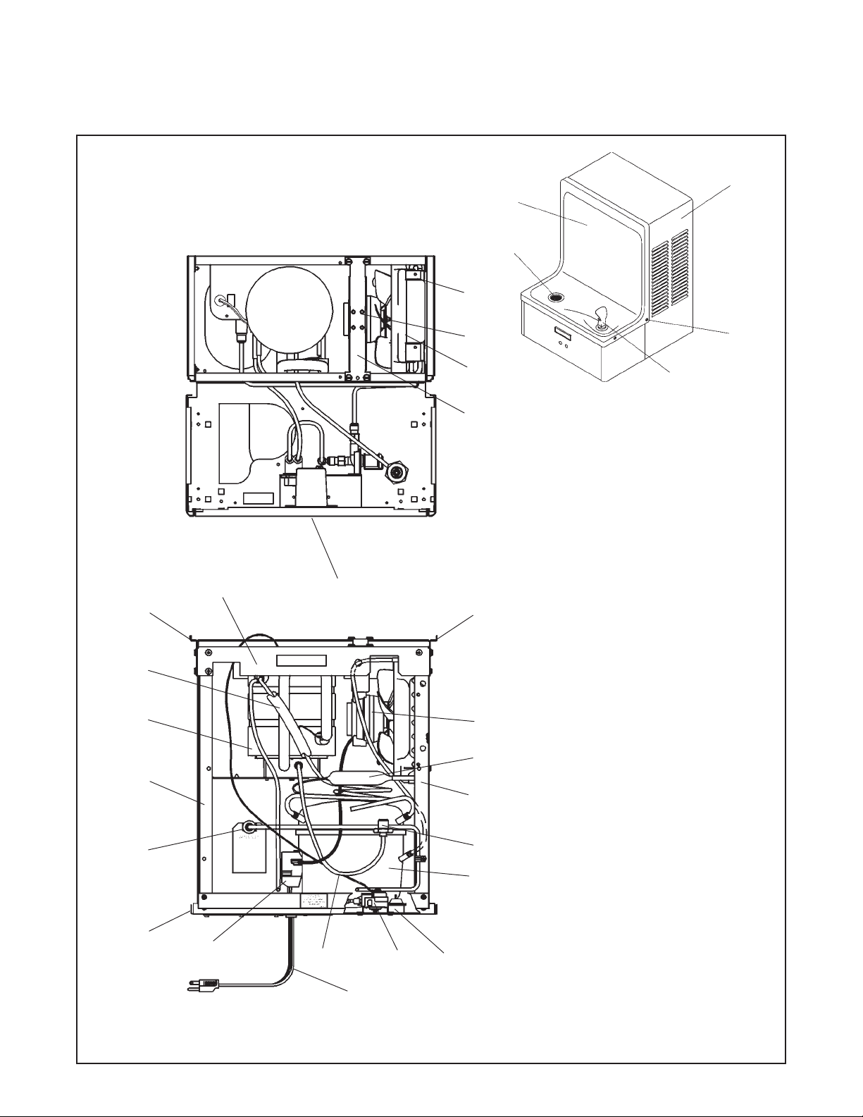
FIG. 1
PAGE 1
29
47
51
34
31,32,33
98064C (Rev. A - 8/05)
WC8AEEQ*1F
ASEGURE UNA VENTILACIÓN ADECUADA MANTENIENDO UN ESPACIO E 6" (152mm) (MÍN.) DE HOLGURA ENTRE LA
REJILLA DE VENTILACIÓN DEL MUEBLE Y LA PARED
ASSUREZ-VOUS UNE BONNE VENTILATION EN GARDANT 6" (152mm) (MIN.) ENTRE LES ÉVENTS DE L’ENCEINTE ET LE
MUR
CABLE ELÉCTRICO DE 1½ PIE, 457 mm DE LARGO
CORDON D’ALIMENTATION 1-1/2' (457mm)
UBICACIÓN ALT. DE LA TOMA DE ELECTRICIDAD
EMPLACEMENT ALTERNATIF DE LA PRISE DE COURANT
ESTE AGUJERO DE TUERCA DEBERÁ SER USADO PARA ASEGURAR LA UNIDAD A LA PARED.
ON DOIT UTILISER CE TROU DE BOULON POUR INSTALLER L’APPAREIL AU MUR.
ALTURA DEL ORIFICIO 1-1/4" (32mm) SOBRE LA CORONA
HAUTEUR DE L'ORIFICE 1-1/4" (32mm) AUDESSUS DU REBORD
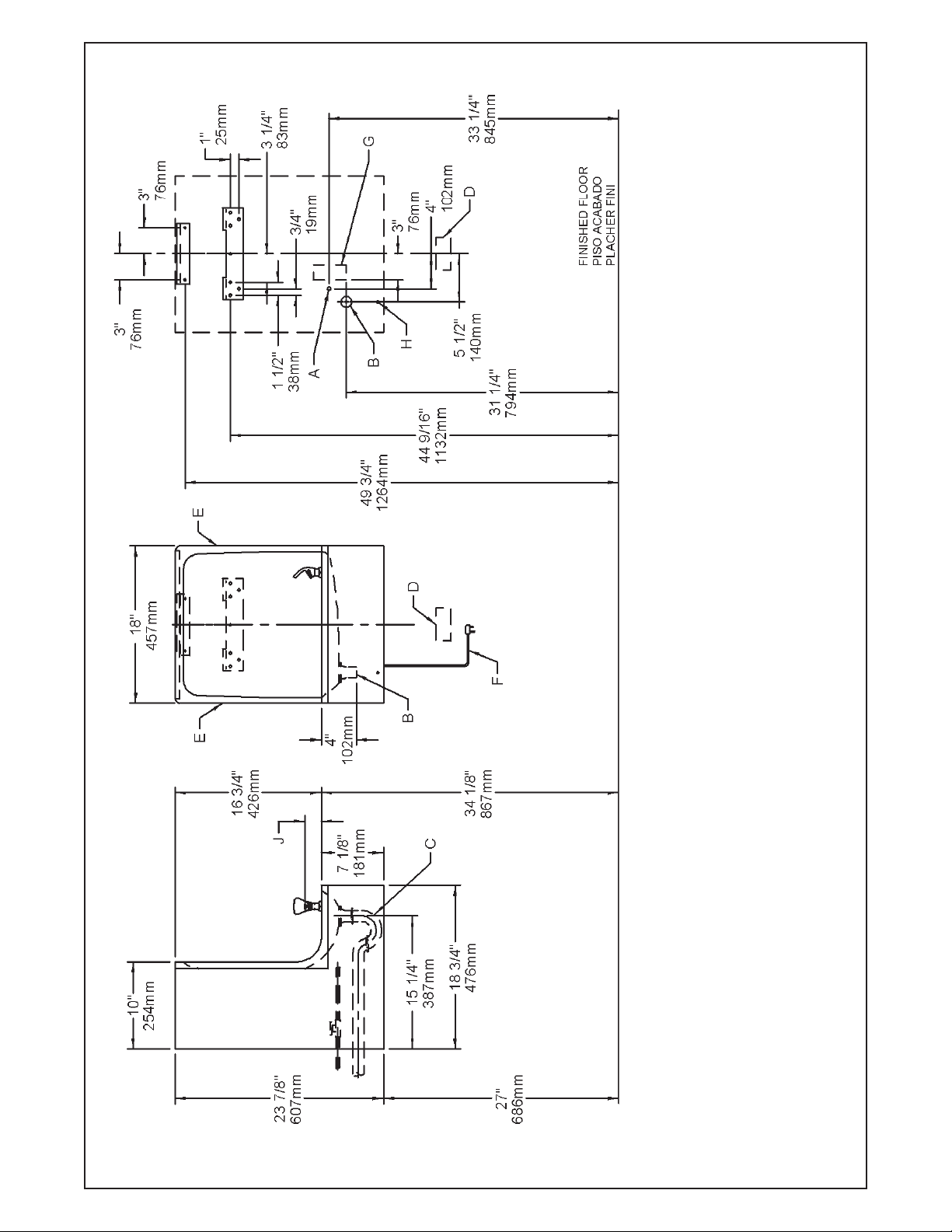
E = INSURE PROPER VENTILATION BY MAINTAINING 6" (152mm) (MIN.) CLEARANCE FROM CABINET LOUVERS TO WALL.
F = POWER CORD 1-1/2FEET (457mm) LONG
G = ALT. ELECTRICAL OUTLET LOCATION
H = THIS BOLT HOLE MUST BE USED FOR FASTENING UNIT TO WALL.
J = ORIFICE HEIGHT 1-1/4" (32mm) ABOVE RIM
FIG. 2
98064C (Rev. A - 8/05)
PAGE 2
FROM WALL SHUT OFF BY OTHERS
1/2" (38mm) FUERA DE LA LLAVE DE PASO EN LA PARED COLOCADA POR TERCEROS.
CONNECTANT UNE TUYAUTERIE DE 1-1/2 PO. (38mm) DEPUIS LE ROBINET D'ARRÊT FOURNI PAR D'AUTRES.
UBICACIÓN RECOMENDADA PARA EL DRENAJE DE SALIDA DE AGUA, DE 1¼” DE DIÁMETRO.
EMPLACEMENT RECOMMANDÉ POUR LE DRAIN DE D.E. 1-1/4" DE SORTIE D’EAU.
PURGADOR DE 1¼ NO PROPORCIONADO**
SIPHON 1-1/4 NON FOURNI**
UBICACIÓN DE LA TOMA DE ELECTRICIDAD
SE RECOMIENDA UBICAR EL TUBO CORTO DE CONEXIÓN AL TUBO DE COBRE SIN CHAPAR DE 3/8" DE DIÁM. EXT. A 1-
LEGEND/LEYENDA/LÉGENDE
A = RECOMMENDED WATER SUPPLY LOCATION 3/8 O.D. UNPLATED COPPER TUBE CONNECT STUB 1-1/2 IN. (38mm) OUT
EMPLACEMENT RECOMMANDÉ D'ALIMENTATION EN EAU PAR TUBE EN CUIVRE NON PLAQUÉ DE 3/8 PO. (9,5 mm) D.E.
B = RECOMMENDED LOCATION FOR WASTE OUTLET 1-1/4” O.D. DRAIN
C = 1-1/4 TRAP NOT FURNISHED**
EMPLACEMENT DE LA PRISE DE COURANT
D = ELECTRICAL OUTLET LOCATION

WC8AEEQ*1F
ELECTRIC EYE MECHANISM
13
6
14
FIG. 3
7
12
14
Sensor Control: If sensor fails to operate valve mechanism or operates erratically, check
the following.
a. Ensure there are no obstructions within a 40-inch radius from front of cooler.
b. Check wire connections at solenoid valve and sensor.
CAUTION: Make sure unit is unpluged before checking any wiring.
c. Ensure proper operation of solenoid valve. If there is an audible clicking sound yet no
water flows, look for an obstruction in the valve itself or elsewhere in the water supply line.
11
Range Adjustment
Screw
15
3
10
2
4
Sensor Range Adjustment: The electronic sensor used in this cooler is factory pre-set
for a "visual" range of 36 inches. If actual range varies greatly from this, or a different
setting is desired, follow the range adjustment procedure below:
a. Remove front panel of cooler.
b.Using a small tip screwdriver, rotate range adjustment screw clockwise to increase
range and counter-clockwise to decrease range. (See Fig. 3).
CAUTION: Complete range of sensor (24-46 inches) is only one turn of the adjusting screw.
c. Replace the front panel.
Note: Water Flow Direction
16
8
9
17
9
1
14
5
HANGER BRACKETS & TRAP INSTALLATION
1) Remove hanger bracket fastened to back of cooler by re-
moving one (1) screw.
2) Mount the hanger bracket and trap as shown in Figure 2.
NOTE: Hanger Bracket MUST be supported securely. Add
fixture support carrier if wall will not provide adequate support.
IMPORTANT:
y 7-3/4 in. (197mm) dimension from wall to centerline of trap
must be maintained for proper fit.
y Anchor hanger securely to wall using all six (6) 1/4 in. dia.
mounting holes.
3) Install straight valve for 3/8" O.D. unplated copper tube.
INSTALLATION OF COOLER
4) Hang the cooler on the hanger bracket. Be certain the
hanger bracket is engaged properly in the slots on the
cooler back as shown in Figure 2.
5) Loosen the two (2) screws holding the lower front panel at
the bottom of cooler base and two (2) screws at the top.
Remove the front panel and set aside.
6) Connect water inlet line--See Note 4 of General Instructions.
7) Remove the slip nut and gasket from the trap and install
them on the cooler waste line making sure that the end of
the waste line fits into the trap. Assemble the slip nut and
gasket to the trap and tighten securely.
START UP
Also See General Instructions
8) Stream height is factory set at 35 PSI. If supply
pressure varies greatly from this, adjust screw, accessible by removing front panel (Item 7, Fig. 3). CW
adjustment will raise stream and CCW adjustment
will lower stream. For best adjustment, stream should
hit basin approximately 6-1/2” (165mm) from bubbler.
9) Replace the front panel and secure by retightening
four (4) screws.
ITEM NO. PART NO.
1
2
3
4
5
6
7
8
9
10
11
12
13
14
15
16
17
26588C
26866C
36028C
31272C
35784C
See Color Table
See Color Table
See Color Table
70817C
75507C
56082C
70644C
75497C
40045C
70864C
61314C
50986C
70002C
COLOR TABLE
PANEL COLOR
Platinum Vinyl
Stainless S teel
Item No. 5
Part No.
26644C
26607C
DESCRIPTION
Panel - Bottom Dispenser
Bracket - Valve Mounting
Sensor - Clear (115v & 230v)
Solenoid Valve (115v)
Solenoid Valve (230v)
Panel - Right Side
Panel - Left Side
Panel - Front
Elbow 1/4 Stem x 1/4 O.D.
Fitting 1/4 NPTF x 1/4 O.D.
Nut- Regulator
Screw #6-32 x 1/2 Lg PHMS
Screw #10 x 1/2 Lg PHSM
Hex Nut
Screw #8 x 5/8 Lg Torx/Slotted
Regulator
Regulator Holder
Screw #10 x 1/2 Lg HHSM
Item No. 6
Part No.
26614C
26637C
Item No. 7
Part No.
26740C
26733C
PAGE 3
98064C (Rev. A - 8/05)

PARTS LIST 115V
WC8AEEQ*1F
ITEM NO. PART NO.
18
19
20
21
22
23
24
25
26
27
28
29
30
31
32
33
34
35
36
37*
38
39
40
41
42
43
44
45
46
47
48
49
50
51
52
31483C
27095C
30664C
70018C
31490C
70009C
56237C
70142C
51544C
100322740560
66743C
66703C
26680C
22708C
50144C
70184C
70150C
36094C
36158C
35768C
35959C
66576C
40572C
40575C
50074C
26664C
75536C
31513C
66534C
55996C
27093C
27094C
27096C
27097C
56159C
56092C
DESCRIPTION
Power Cord
Fan Bracket
Fan Blade
Hex Nut - Fan Blade
Fan Motor
Screw - (Fan Motor)
Shroud - Fan
Clip (Front and Rear Panels)
Bubbler - Chrome
Gasket - Bubbler (upper and lower)
Condenser
Drier
Wrapper - Platinum
Wrapper-Stainless Steel
Grommet - Compressor Mtg.
Hair Pin - Cotter
Washer
Compressor Serv. Pak EMI 70 HNR
Overload
Cover - Relay
Relay
Heat Exchanger
Tailpipe
Strainer Assy - Basin
Gasket - Tailpipe
Basin - Stainless Steel
Screw - Basin Mtg.
Cold Control
Evaporator Assembly
Strainer
Angle - Front Corner
Bracket - Front Support
Bracket - Basin Mounting
Frame - Back/Bottom
Nipple - Bubbler
Poly Tubing (Cut To Length)
WIRING DIAGRAM
This Drawing is merely for illustrating the
components of the electrical system.
*INCLUDES RELA Y & OVERLOAD. IF UNDER WARRANTY , REPLACE
WITH SAME COMPRESSOR USED IN ORIGINAL ASSEMBLY.
NOTE: All correspondence pertaining to any of the above water
coolers or orders for repair parts MUST include Model No. and Serial
No. of cooler, name and part number of replacement part.
CORRECT STREAM HEIGHT
FIG. 4
2222 CAMDEN COURT
OAK BROOK, IL 60523
630.574.3500
PRINTED IN U.S.A.
FOR PARTS, CONTACT YOUR LOCAL DISTRIBUTOR OR VISIT OUR WEBSITE WWW.HALSEYTAYLOR.COM
98064C (Rev. A - 8/05)
PAGE 4
 Loading...