

Halsey Taylor SJ10-Q User Manual
MODEL:
■■
SJ5-Q
■■
SJ8-Q
■■
SJ10-Q
RREEMMOOTTEE CCHHIILLLLEERRSS
MMooddeell GGPPHH CCaappaacciittyy BBaassee FF..LL.. SShhiippppiinngg RRaatteedd
NNoo.. CCoooolleedd ttoo 5500°° FF** RRaattee AAmm ppss WWeeiigghhtt WWaatttt
AAmmbbiieenntt AAiirr TTeemmpp
CCaapp.. llbb.. UUssaaggee
7700°°FF 8800°°FF 9900°°FF†110000°°FF
SSJJ55--QQ
6.8 6.3 5.7 5.1 5.0 3.5 72 320
SSJJ88--QQ
9.6 8.8 8.0 7.2 8.0 3.5 47 325
SSJJ1100--QQ
11.5 10.6 9.6 8.6 10.0 6.0 73 490
**
With projector service at 1 ft. from outlet and supply water at 80° F
†
UL listed and complies with ARI Standard 1010
NOTE: A service supply stop (not included) should be installed at the cooler inlet line.
Remote Chillers
www.halseytaylor.com
SJ5-Q
SJ8-Q
SJ10-Q
JOB NAME:
ENGINEER/CONTRACTOR NAME:
APPROVAL:
DATE:
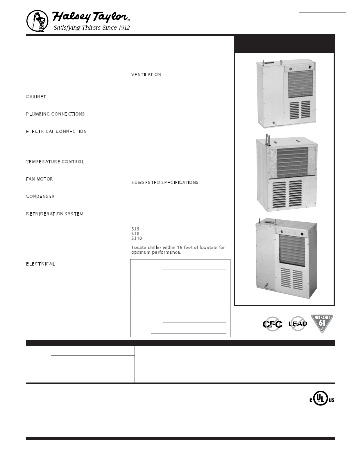
AB IN E T
Manufactured of rust-resistant heavy gauge
galvanized steel. Removable service panels.
P LUMB ING C ON NE C TIONS
3
⁄8" O.D. inlet and outlet (SJ5-Q and SJ10-Q)
1
⁄4" O.D. inlet and outlet (SJ8-Q)
E LE C TR IC AL CON NE CTIO N
7
⁄8" diameter opening for conduit connection.
COOLING COIL
Tube-type. Tube is continuous coil of
copper-tubing.
T E MP ER ATU R E C ON TR OL
Thermostat for cooling and storage tank is
factory set for 50° F water. Adjustable ± 5° F.
FA N MOT OR
Unit bearing self-lubricating type for
maintenance-free longer life.
C OND E NS E R
Copper/aluminum construction with associated
shroud.
R E FR IGE R AT IO N S YS TE M
Hermetically sealed, positive start compressor
with lifetime lubrication and built-in overload
protection, ecient capillary sizing, large
capacity dryer-strainer, and self-lubricated fan
cools copper/aluminum condenser. System
uses R134A refrigerant. Test pressures,
highside 325 psig., lowside 140 psig.
Protected by Halsey Taylor’s Limited 5 Year
Warranty.
E LE C T RIC AL
Furnished with 6" leads enclosed in junction
box for direct connection to standard 115 volt,
60 Hz, single phase.
V E NT ILATION
SJ8-Q
When mounting unit in an open area, to insure
proper ventilation, maintain a 4" (102mm)
clearance from cabinet louvers on each side
of cooler. When mounting unit in a cavity or
behind a wall, maintain a minumum space of 4"
(102mm) on each side, 4" (102mm) on the top
and a depth of 12" (305mm).
SJ5-Q and SJ10-Q
It is important to insure proper ventilation. Allow
a minimum clearace of 6" (152mm) in front and
3" (76mm) in the rear of the unit. If unit is to be
installed in an enclosure, allow the following
clearances around unit: 1 inch (25mm) on each
side, 3 inches (76mm) in the rear and 3 inches
(76mm) inches above wall.
NOTE: Continued product improvement makes
specifications subject to change without notice.
See Halsey Taylor website for most current
spec sheet.
S UG GE STE D S P E CIFIC ATIONS
Shall deliver ( ) GPH of 50°F water at 90°F
ambient and 80°F inlet water. Designed for
use with any drinking fountain. Compressor
shall be hermetically sealed. Manufacturer shall
certify unit to meet the requirements of NSF/ANSI 61
and 372 and Safe Drinking Water Act. System
controlled by adjustable thermostat. Complies
with ARI Standard 1010.
S
J 5
can serve 1 fountain
J 8
S
can serve 2 fountains
J 10
S
can serve 3 fountains
L oc ate chille r within 15 feet of fountain for
optimum performa nce.
HALSEY TAYLOR, 2222 CAMDEN COURT, OAK BROOK, ILLINOIS 60523
E3
/ 10-2013
Printed in the U.S.A.
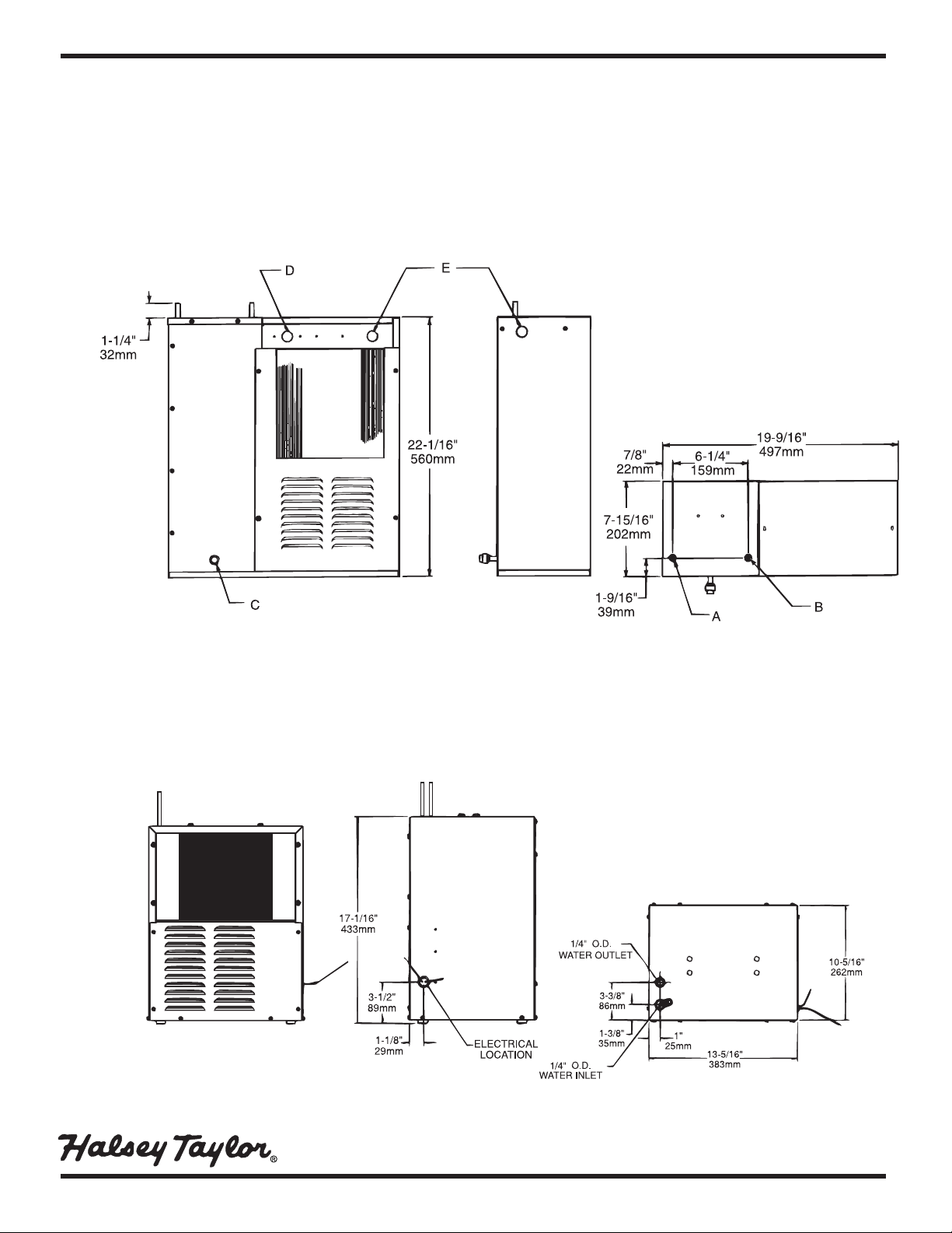
RReemmoottee CChhiilllleerrss
(CONTINUED)
MMOODDEELL::■■SSJJ55--QQ
■■
SSJJ1100--QQ
DDiimmeennssiioonn ss
19
9
/
16
"W x 7
15
/
16
"D x 22
1
/
16
"H
MMiinniimmuumm WWaallll OOppeenniinngg
21
1
/
2
"W x 10
7
/
8
"D x 25"H
Shipping weight: 67 lbs.
MMOODDEELL::■■SSJJ88--QQ
DDiimmeennssiioonn ss
13
5
/
16
"W x 10
5
/
16
"D x 17
1
/
16
"H
MMiinniimmuumm WWaallll OOppeenniinngg
21
1
/
4
"W x 13"D x 21"H
Shipping weight: 56 lbs.
OOPPEERRAATTIINNGG PPRREESSSSUURREESS::
Supply water - 105 psi maximum
FRONT VIEW SIDE VIEW TOP VIEW
FRONT VIEW SIDE VIEW TOP VIEW
LEGEND:
A = 3/8" O.D. TUBE WATER OUTLET
B = 3/8" O.D. TUBE WATER INLET
C = 3/8" O.D. TUBE TANK DRAIN
D = TEMPERATURE ADJUSTMENT
E = ELECTRICAL
NOTE: A service supply stop (not included) should be installed at the cooler inlet line.
 Loading...