

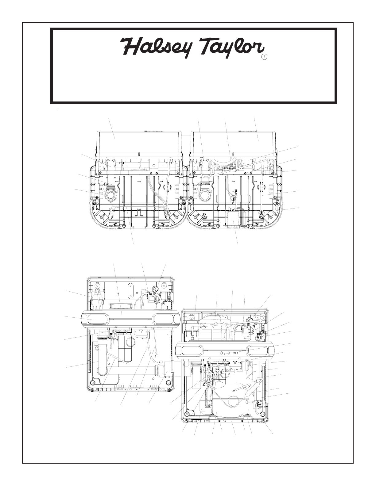
HTV8BLEEMVP*1C HTV8BLEEMVP*2C HVT8BLEEMVP*3C HTVDBLMVP*1C HTVDBLMVP*2C HTVDBLMVP*3C
OWNERS MANUAL
HTVBLEE-MVP Series Barrier-Free Water Coolers
49
41
62
56
43 53
24
34
17
23, 36, 51
64
69
54, 68 23, 36, 51
12
44
27
52
8
58
6
35
1, 47
40
22, 29
31
Fig. 1
35
35
28
45, 46
77
21, 29
33
67
30
(A) - See. Fig. 10
4, 16
15, 59, 60
13
42
55
57
63
18,
20,
26
PAGE 1 98496C (Rev. C - 7/09)
25
65
65
2, 3, 5
7
66, 70

HTV8BLEEMVP*1C HTV8BLEEMVP*2C HVT8BLEEMVP*3C HTVDBLMVP*1C HTVDBLMVP*2C HTVDBLMVP*3C
Reduzca la altura por 3” (76 mm) para
la instalación de childrens ADA más fresco.
Reduce height by 3” (76mm) for
*ADA REQUIREMENT
*REQUISITO DE A.D.A.
*EXIGENCE ADA
installation of childrens ADA cooler.
Réduire la hauteur par 3 (76 mm) pour
l’installation de childrens ADA plus frais.
NOTE: Halsey Taylor’s recommended orifice
mounting height for children 38” to 46” tall
(approx. four through seven years old) is 23”
from the finished floor.
Fig. 2
PAGE 298496C (Rev. C - 7/09)
COPPER TUBE.
LEGEND/LEYENDA/LÉGENDE
A = RECOMMENDED WATER SUPPLY LOCATION. SHUT OFF VALVE (NOT FURNISHED) TO ACCEPT 3/8” O.D. UNPLATED
La UBICACION RECOMENDADA de ABASTECIMIENTO DE AGUA. APAGUE V ALVULA (no AMUEBLADO) ACEPTAR 3/8 O. D.
UBICACIÓN RECOMENDADA P ARA EL DRENAJE DE SALIDA DE AGUA, DE 1¼” DE DIÁMETRO.
EMPLACEMENT RECOMMANDÉ POUR LE DRAIN DE D.E. 1-1/4" DE SORTIE D’EAU.
El TUBO del COBRE de UNPLATED
L’EMPLACEMENT DE PROVISION D’EAU RECOMMANDE. ETEINDRE LA SOUPAPE (P AS FOURNI) ACCEPTER 3/8 O.D. LE TUBE DE
CUIVRE DE UNPLATED.
B = RECOMMENDED LOCATION FOR WASTE OUTLET 1-1/4” O.D. DRAIN
C = 1-1/2 TRAP NOT FURNISHED**
PURGADOR DE 1-1/2 NO PROPORCIONADO**
SIPHON 1-1/2 NON FOURNI**
CAJA RECESIV A DE ALAMBRES (3) DE SUMINISTRO ELÉCTRICO
BOÎTE ENCASTRÉE D’ALIMENTATION ÉLECTRIQUE (3) FILS
ASEGURE UNA VENTILACIÓN ADECUADA MANTENIENDO UN ESPACIO E 6" (152 mm) (MÍN.) DE HOLGURA ENTRE LA REJILLA DE
VENTILACIÓN DEL MUEBLE Y LA PARED
ASSUREZ-VOUS UNE BONNE VENTILATION EN GARDANT 6" (152 mm) (MIN.) ENTRE LES ÉVENTS DE L’ENCEINTE ET LE MUR.
AGUJEROS DE LAS TUERCAS DE 5/16 PARA SUJETAR LA UNIDAD A LA PARED
TROUS D’ÉCROUS 5/16 POUR FIXER L’APP AREIL AU MUR
D = ELECTRICAL SUPPLY (3) WIRE RECESSED BOX
E = INSURE PROPER VENTILATION BY MAINTAINING 6" (152 mm) (MIN.) CLEARANCE FROM CABINET LOUVERS TO WALL.
F = 5/16 BOLT HOLES FOR FASTENING UNIT TO WALL
HTV8BLEEMVP*1C HTV8BLEEMVP*2C HVT8BLEEMVP*3C HTVDBLMVP*1C HTVDBLMVP*2C HTVDBLMVP*3C
HANGER BRACKET & TRAP INST ALLATION
1) Remove the hanger bracket fastened to back of the
cooler by removing one (1) screw.
2) Mount the hanger bracket as shown in Fig. 2 & Fig 3.
NOTE: Hanger Bracket MUST be supported securely.
Add fixture support carrier if wall will not provide
adequate support. Anchor hanger securely to wall
using all six (6) 1/4 in. dia. mounting holes.
IMPORTANT:
7 in. (178mm) dimension from wall to centerline
of trap must be maintained for proper fit.
INSTALLATION OF COOLER
3) Hang the cooler on the hanger bracket. Be certain the
hanger bracket is engaged properly in the slots on the
cooler back as shown in Figure 3.
4) Remove the two (2) screws holding the bottom cover
at the bottom of cooler. (Shown in Fig. 16) Remove the
bottom cover by pulling straight down and set aside.
5) Connect water inlet line--See Note 4 of General Inst.
6) Install trap. Remove the slip nut and gasket from the
trap and install them on the cooler waste line making
sure that the end of the waste line fits into the trap.
Assemble the slip nut and gasket to the trap and tighten
securely.
IMPORTANT: If it is necessary to cut the wasteline, loosen
the clamp (Item 62) at the drain fitting (Item 41)
and remove. Check for leaks after re-assembly.
8) Plug in electrical power and re-install bottom cover. Unit
must have electrical power to have water flow.
HANGER BRACKET (Item 10)
COOLER BACK
Fig. 3
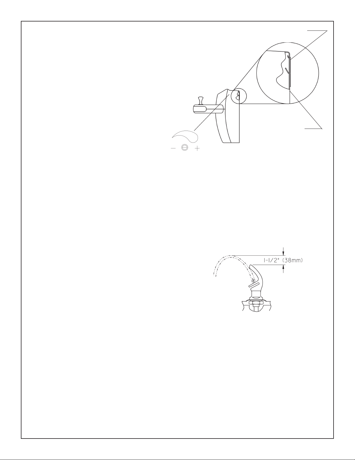
ST ART UP
Also See General Instructions
9) Stream height is factory set at 35 PSI. If supply pressure
varies greatly from this, adjust screw located on upper
side of frame (Item 43 or 44). See Fig. 3. CW adjustment
will raise stream and CCW adjustment will lower stream.
For best adjustment, stream should be 1-1/2” above
bubbler hood. (See Fig. 4)
NOTE: If continuous flow occurs at the end of the
compressor cycle, turn cold control (Item 16)
counterclockwise 1/4 turn.
CAUTION: PLASTIC COMPONENTS
Any service of this unit that requires use of a torch,
care should be taken not to melt any of the plastic
components. To keep flame away from plastic, the
use of a shield may be required.
CLEANING:
Warm, soapy water or mild household cleaning products
can be used to clean the exterior panels of the HTV
series coolers. Use of harsh chemicals or petroleum
based cleaners WILL VOID THE WARRANTY.
CORRECT STREAM
HEIGHT
Fig. 4
IMPORT ANT:
When installing cooler, do not solder 3/8” copper inlet tube
while inserted into union fitting as damage to o-ring and
plastic will result.
PAGE 3 98496C (Rev. C - 7/09)
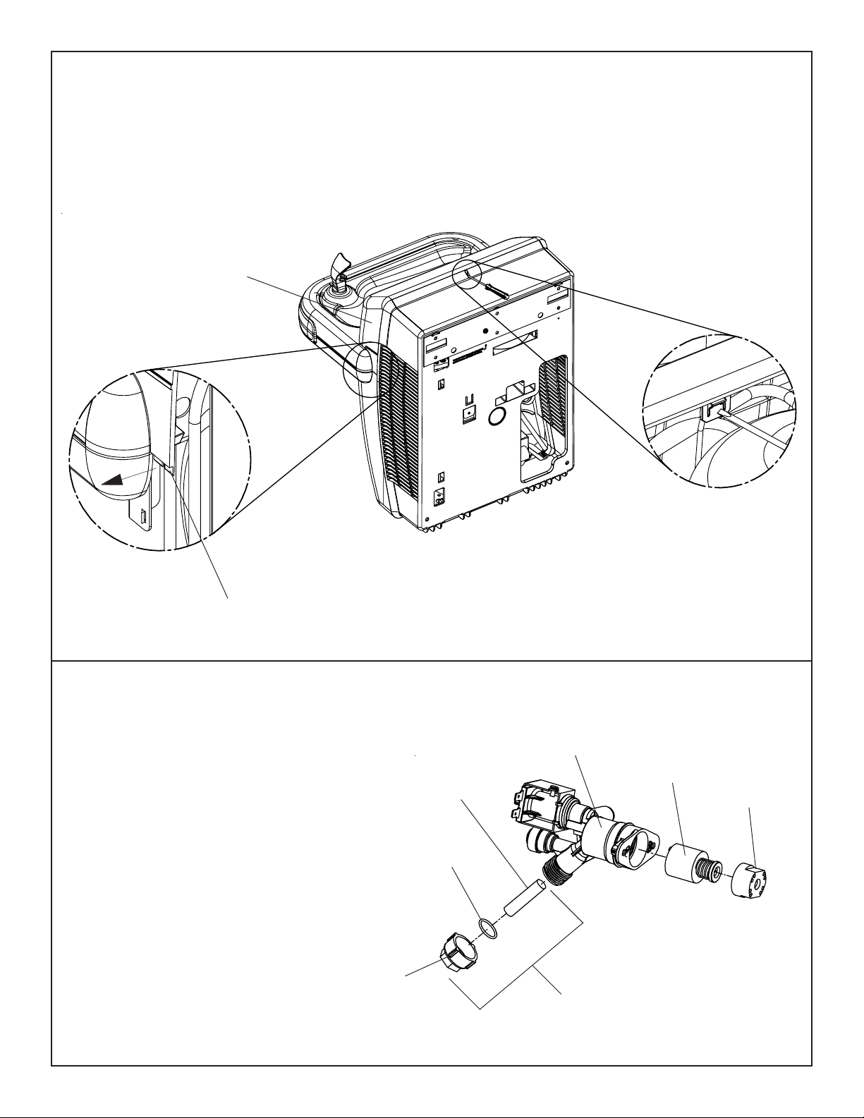
HTV8BLEEMVP*1C HTV8BLEEMVP*2C HVT8BLEEMVP*3C HTVDBLMVP*1C HTVDBLMVP*2C HTVDBLMVP*3C
Top Cover Removal
Please remove bottom cover before removing top cover. To remove top cover
(Item 37), use a small screwdriver to release the snap for the top cover as shown
in Fig. 5. Then pull the small tabs on each side of the top cover outward slightly
and slide upward to remove.
FIG. 5
37
Small tabs
Cleaning the strainer
To clean the strainer, unscrew the cap of the
solenoid valve. Remove screen and rinse
thoroughly with water. Insert screen back
into solenoid valve and screw cap on. Make
sure the o-ring is placed properly.
Retén anular
Joint Torique
Cap
Tapa
Bouchon
Screen
Malla
Ecran
O-ring
FIG. 6
23
51
36
76
PAGE 498496C (Rev. C - 7/09)

HTV8BLEEMVP*1C HTV8BLEEMVP*2C HVT8BLEEMVP*3C HTVDBLMVP*1C HTVDBLMVP*2C HTVDBLMVP*3C
Removing the basin
To remove the basin (Item 12 or 34), remove two screws (Item 58) on top of the basin
(Shown in Fig. 7). Then remove the four screws (Item 71) located underneath the
dispenser bottom (Item 39 or 50) as shown in Fig. 7. Finally pull polytube (Item 35)
out of bubbler nipple (Item 47) as shown in Fig. 8. and remove the basin.
FIG. 7
58
58
12 or 34
71
FIG. 8
1
35
33
47
See figure below for
Operation of Quick
Connect Fittings
FIG. 9
Filter Installation Detail
(Some parts hidden for clarity)
48, 65
49
PAGE 5 98496C (Rev. C - 7/09)

HTV8BLEEMVP*1C HTV8BLEEMVP*2C HVT8BLEEMVP*3C HTVDBLMVP*1C HTVDBLMVP*2C HTVDBLMVP*3C
SENSOR RANGE ADJUSTMENT: (A)
The electronic sensor used in this cooler is factory pre-set for a “visual” range of
36 inches (914 mm). If actual range varies greatly from this or a different setting
is desired, follow the range adjustment procedure below:
- Using a small tip screwdriver, locate range adjustment screw through the
small hole between the sensor lenses (A). Turn this screw clockwise to
increase range and counterclockwise to decrease range.
CAUTION: Complete range of sensor (24-46 inches/610-1168mm) is only one
turn of the adjusting screw.
SENSOR CONTROL: If sensor fails to operate valve mechanism or operates
erratically, check the following.
A. Ensure there are no obstructions within a 40 inch (1016mm) radius in front
of cooler.
B. Check wire connections at the solenoid valve and sensor.
CAUTION: Make sure unit is unplugged before checking any wiring.
C. Ensure proper operation of solenoid valve. If there is an audible clicking
sound yet no water flows,look for an obstruction in the valve itself or
elsewhere in the water supply line.
65
FIG. 10
32
Green
Yellow
50
9
27
11
74
Red
(A)
PAGE 698496C (Rev. C - 7/09)

HTV8BLEEMVP*1C HTV8BLEEMVP*2C HVT8BLEEMVP*3C HTVDBLMVP*1C HTVDBLMVP*2C HTVDBLMVP*3C
SENSOR WITH FILTER LIFE INDICATOR: (B)
The electronic sensor includes LED filter status indicators that are factory preset to monitor filter life. The sensor monitors the “ON” time
of the water valve solenoid and keeps track of total time water is dispensed. There are (3) LED’s and indicates the following:
Once power is applied to the water cooler, if all three LED’s flash then the Green LED aluminates, this indicates that there is some filter
usage memory stored. When the Green LED comes on only, this indicates that the filter life is at absolute 0% of filter life. NOTE: You
may have some very minimal filter life in memory upon receiving water cooler due to factory functional testing.
NOTE: The filter status will be retained until reset (see resetting filter monitor). The filter monitor will retain its memory even
during a loss of power.
Green LED (Good) indicates that the filter is operating within 0% - 80% of its life.
Yellow LED indicates that the filter is operating within 80% - 100% of its life.
Red LED (Replace) indicates that the filter needs to be replaced since it has reached end of filter life.
RESETTING FILTER LIFE INDICATOR: (C)
In order to reset the filter life indicator status LED’s, you must remove the finishing plug (Item 75) underneath the front dispenser. With a
straight blade screw driver or pen, reach inside opening and depress the reset button located on the back of the sensor as seen on
a minimum of 1 second. (You may need a flashlight). Reinstall finishing plug and the Green LED should be illuminated indicating that the
visual filter monitor has been reset.
(B)
(C) for
FIG. 11
(C) - Reset Button
75
PAGE 7 98496C (Rev. C - 7/09)

HTV8BLEEMVP*1C HTV8BLEEMVP*2C HVT8BLEEMVP*3C HTVDBLMVP*1C HTVDBLMVP*2C HTVDBLMVP*3C
Switch Activation Detail
FIG. 12
40
19
Closed switch
40
19
Open switch
PAGE 898496C (Rev. C - 7/09)

HTV8BLEEMVP*1C HTV8BLEEMVP*2C HVT8BLEEMVP*3C HTVDBLMVP*1C HTVDBLMVP*2C HTVDBLMVP*3C
FIG. 13
73
72
73
40
Pushbar Replacement
Please remove the basin before removing the pushbars.
Remove screw (Item 73) that holds pushbars in place. Then
simply slide the pushbars upward and remove. Do not discard the
small springs or screws. When replacing pushbars do not over
tighten screws, because the pushbars need to move freely.
See Figures 13 & 14 for proper spring placement.
FIG. 14
72
PAGE 9 98496C (Rev. C - 7/09)

HTV8BLEEMVP*1C HTV8BLEEMVP*2C HVT8BLEEMVP*3C HTVDBLMVP*1C HTVDBLMVP*2C HTVDBLMVP*3C
See
Fig. 10
40
73
12
58
62
53
33
1
1
46
73 40
58
FIG. 15
58
37
10
58
44
41
50
71
75
71
71
Bottom Cover Removal
To access the refrigeration system and plumbing
connections, remove two screws (Item 66) to remove
bottom cover (Item 38).
32, 36, 51
71
61
6
61
58
38
70
66
70
66
PAGE 1098496C (Rev. C - 7/09)

HTV8BLEEMVP*1C HTV8BLEEMVP*2C HVT8BLEEMVP*3C HTVDBLMVP*1C HTVDBLMVP*2C HTVDBLMVP*3C
FIG. 16
28
CONNECTS TO
SENSOR ON
REFRIG. SIDE UNIT
HTVD8BL-MVP - 115V
SOLENOID
17
VALVE
PURPLE
JUMPER
SMOOTH
(LINE)
RIBBED
(NEUTRAL)
WIRING DIAGRAM
GND
GREEN
FIG. 17
COMPRESSOR
BLACK
LED PCB
RED
WHITE
GREEN
WHT
BLK
SENSOR
RED
OVERLOAD
3
1
2
C
S
M
6
5
3
2
1
RELAY
FAN
SOLENOID
COLD CONTROL
SMOOTH (LINE)
RIBBED
(NEUTRAL)
MALE TERMINAL ON
WHITE SHORT LEAD
ON POWERCORD
YELLOW
PURPLE JUMPER
GRND
VALVE
GREEN
14 (Black Jumper Wire)
GND
CONNECTS TO SENSOR
ON LESS REFRIG. UNIT
WIRING DIAGRAM
HTV8BLEE-MVP - 115V
FIG. 18
28
CONNECTS TO
SENSOR TO
REFRIG. SIDE UNIT
SMOOTH LEAD
TO "L" TERMINAL
ON POWER INLET
17
PURPLE
JUMPER
GREEN LEAD TO
GROUND TERMINAL
ON POWER INLET
SOLENOID
VALVE
RIBBED LEAD
TO "N" TERMINAL
ON POWER INLET
GND
GREEN
FIG. 19
OVERLOAD
COMPRESSOR
RELAY
BLACK
LED PCB
RED
WHITE
GREEN
WHT
BLK
SENSOR
RED
SOLENOID
3
1
2
C
S
M
6
5
3
2
1
FAN
RIBBED LEAD
TO "N" TERMINAL
ON POWER INLET
GREEN LEAD TO
"GROUND" TERMINAL
ON POWER INLET
COLD CONTROL
YELLOW
PURPLE
GND
CONNECTS TO SENSOR
VALVE
GREEN
ON LESS REFRIG. UNIT
14 (Black Jumper Wire)
MALE TERMINAL ON
WHITE SHORT LEAD
ON POWERCORD
GND
SMOOTH LEAD
TO "L" TERMINAL
ON POWER INLET
WIRING DIAGRAM
HTVD8BL-MVP - 220V-50/60Hz
WIRING DIAGRAM
HTV8BLEE-MVP - 220V-50/60Hz
PAGE 11 98496C (Rev. C - 7/09)

HTV8BLEEMVP*1C HTV8BLEEMVP*2C HVT8BLEEMVP*3C HTVDBLMVP*1C HTVDBLMVP*2C HTVDBLMVP*3C
PARTS LIST
ITEM NO.
1
2
3
4
5
6
7
8
9
10
11
12
13
14
15
16
17
18
19
20
21
22
23
24
25
*
26
27
28
29
30
31
32
33
34
35
36
37
38
39
40
41
42
43
44
45
46
47
48
49
50
51
52
53
54
55
56
57
58
59
60
61
62
63
64
65
66
67
68
69
70
71
72
73
74
75
76
77
*REPLACE WITH SAME COMPRESSOR USED IN ORIGINAL ASSEMBL Y.
NOTE: All correspondence pertaining to any of the above water coolers or orders
for repair parts MUST include Model No. and Serial No. of cooler, name and part
number of replacement part.
PART NO.
100322740560
100806740570
101516143550
111411443890
19037000
28237C
28238C
28239C
28246C
28266C
28803C
28836C
30646C
30873C
31490C
31513C
33133000
35768C
35948C
35959C
36285C
35980C
36247C
36279C
36094C
36158C
36263C
36265C
38397000
38417001
45875C
75717C
51544C
55001122
56092C
56082C
56098C
56102C
56106C
56110C
56118C
56122C
56128C
56132C
56154C
56155C
56159C
56190C
56191C
56291C
66654C
66661C
45893C
66700C
66703C
45893C
66762C
70002C
70009C
70018C
75718C
70444C
70682C
70683C
75722C
75532C
75533C
75568C
75583C
75599C
75663C
75621C
75625C
75715C
75716C
98169C
36090C
DESCRIPTION
Gasket - Bubbler (upper and lower)
Grommet - Compressor Mtg.
Stud - Compressor Mtg.
Screw - #8 -36 x .38 Tri-Lobed
Clip - Compressor Mtg.
Support Brace
Compressor Base
Bracket - Fan Motor
Bracket - EE
Hanger Bracket
Bracket - Mtg.
Basin - (Filter Monitor Unit)
Fan Blade
Jumper Wire - Black
Fan Motor
Cold Control
Adapter Tab
Cover - Relay
Switch Electrical
Relay
Power Cord (Refrig. Unit)
Power Cord (Less Refrig. Unit)
Solenoid Valve
Wiring Harness
Compressor Serv. Pak EMI 70
Overload
Sensor - EE (Filter Monitor)
Jumper Wire (Purple)
Bushing - Strain Relief
Screw - #8-18 x .37 HHSM
Waste Line Assy.
Rivet - Push In
Bubbler - Chrome
Tubing - Poly (Cut To length)
Dispenser Bottom (Less Refrig. Unit)
Dispenser Bottom (Refrig. Unit)
Waste Line (Less Refrig. Unit)
Screw - #10 x 1/2” Lg. HHSM
Screw - #8-18 Flat hd. Torx Drive
Screw - #10-16 x .63” THSM
Kit - Replacement Cap/Screen/O-Ring
Basin
Regulator Nut
Top Cover
Bottom Cover
Pushbar
Fitting - Drain
Fan Shroud
Frame (Less Refrig. Unit)
Frame (Refrig. Unit)
Bushing
Drain Cover
Nipple - Bubbler
Bracket - Filter Mounting
Filter Assembly
Regulator
Heat Exchanger
Waste Line (Refrig. Unit)
Evaporator Assembly
Drier
Condenser
Screw - Fan Motor
Hex Nut
Clamp - Drain Gasket
Fitting - Tee 1/4”
Fitting - Union 1/4”
Screw - #8-18 HH Self Tap
Screw - #8 x .63 HHSM
Screw #12 x 1.50” HHSM
Fitting - Elbow 5/16” x 1/4”
Clip - Tinnerman
Screw - #10 x .50 HHSM
Spring - Pushbar
Screw - HTV Pushbar
Rivet - Push In Ratcheting
Finishing Plug
Ground Wire - Green
ITEM NO.
15
20
21
22
23
25
*
26
78
NS
ITEM NO.
15
20
21
22
23
25
*
26
78
NS
FIG. 20
220V-50Hz PARTS LIST
PART NO.
31431C
36050C
36066C
36067C
36248C
36085C
36195C
35826C
28350C
220V-60Hz PARTS LIST
PART NO.
31431C
36050C
36066C
36067C
36248C
36092C
36174C
35826C
28350C
78 (220V)
DESCRIPTION
Fan Motor
Relay
Power Cord (Refrig. Unit)
Power Cord (Less Refrig. Unit)
Solenoid Valve
Compressor Serv. Pak
Overload
Power Inlet
Bracket - Power Inlet
DESCRIPTION
Fan Motor
Relay
Power Cord (Refrig. Unit)
Power Cord (Less Refrig. Unit)
Solenoid Valve
Compressor Serv. Pak
Overload
Power Inlet
Bracket - Power Inlet
2222 CAMDEN COURT
OAK BROOK, IL 60523
630.574.3500
FOR PARTS CONTACT YOUR LOCAL DISTRIBUTOR OR VISIT OUR WEBSITE WWW.HALSEYTAYLOR.COM
REPAIR SERVICE INFORMATION TOLL FREE NUMBER 1.800.260.6640
PAGE 1298496C (Rev. C - 7/09)
PRINTED IN U.S.A.
 Loading...