

Halsey Taylor HTHB-HVRGRN8BL-NF User Manual
Satisfying Thirsts Since 1912
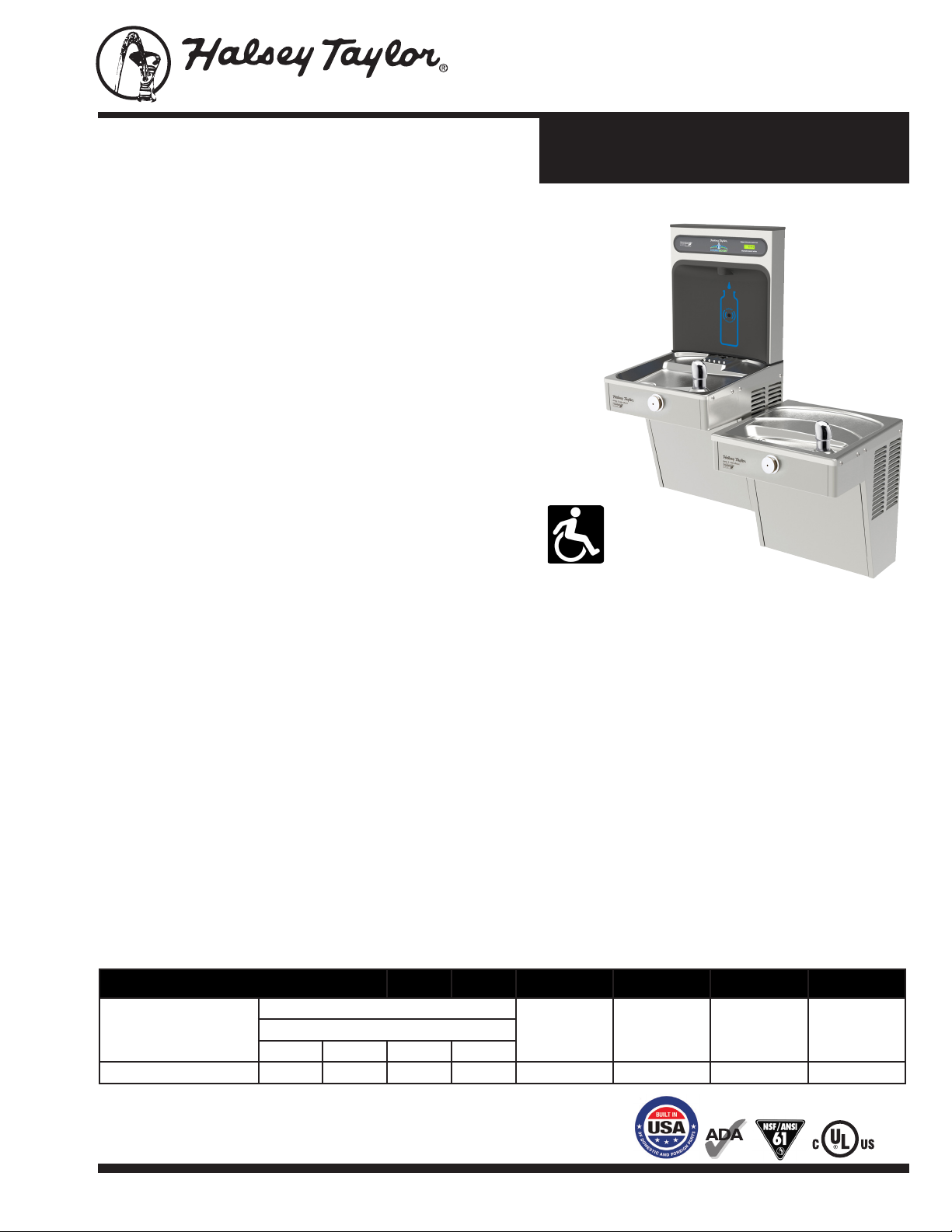
Model HTHB-HVRGRN8BL-NF
Bi-Level HVR Green Cooler with
Hydroboost® Bottle Filler
HTHB-HVRGRN8BL-NFMODEL:
GENERAL
Complete water station including HydroBoost® bottle lling
station and HVR Green Single water cooler.
GreenSpec® Listed, energy and water efcient bi-level water
cooler model. Self-contained, wall-mounted, electric,
refrigerated model. One-piece chrome-plated vandal-resistant
water conservation bubbler with integral hood. Automatic stream
height regulator is located inside unit to prevent tampering.
Includes self-closing, light touch front pushbutton actuation. Type
300 series stainless steel cooler top, with satin nish resists
stains. Anti-splash ridge reduces splatter. Contoured to insure
proper drainage.
HYDROBOOST® BOTTLE FILLING STATION
Sensor-activated enhanced with user interface graphics. Quick
ll rate is 1.1 gallons per minute. Laminar ow provides a clean
ll with minimal splash and easy maintenance. Equipped with an
automatic 20-second shut-off timer.
SILVER ION ANTI-MICROBIAL PROTECTION
Key plastic components are integrated with silver ion
anti-microbial protection to inhibit growth of mold and mildew.
GREEN COUNTER™
Visually displays count of plastic bottles saved from the landlls.
(Based on 20 oz. bottles for refrigerated models)
HVR Green Cooler
with Bottle Filler
*Rated for Indoor Use Only
Model
HTHB-HVRGRN8BL-NF
PUSHBUTTON ACTUATION MECHANISM
Self-closing, vandal-resistant pushbutton does not require
grasping or twisting.
SUGGESTED SPECIFICATION
Unit shall include a bi-level water cooler with a bottle lling
AUTOMATIC STREAM HEIGHT REGULATOR
Self-closing assembly is located inside unit to prevent tampering.
Unit resists corrosion and liming. A constant stream height is
automatically maintained under line pressures that vary from
20 to 105 psi.
station. Units shall have a high-efciency refrigeration
system and deliver 8 gph of 50°F drinking water at 90°F ambient
air and 80°F inlet water. Lower units shall have mechanically
activated pushbutton activation. Bottle ller shall include
electronic sensor for no-touch activation with automatic
20-second shut-off timer. Shall include a Green Counter™
WATER INLET - 3/8” O.D. Tubing. DRAIN OUTLET - 1-1/2” tube outlet for
1-1/2” slip joint connection. Trap and service stop not included.
displaying the count of plastic bottles saved from the landll.
Shall provide 1.1 gpm with laminar ow to minimize
splashing. Shall include anti-microbial protected plastic
REFRIGERATION SYSTEM
Hermetically sealed, positive start compressor with lifetime
lubrication and built-in overload protection, efcient capillary
sizing, large capacity dryer-strainer and self-lubricated fan cools
copper/ aluminum condenser. System uses R-134A refrigerant.
Protected by Halsey Taylor’s Limited 5 Year Warranty.
components to prevent mold and mildew. Cooler shall have
stainless steel cabinet and basin. Cooler shall include
removable drain strainer. Shall comply with ADA guidelines
for visual and motion disabilities. The manufacturer shall
certify the unit to meet the requirements of
NSF/ANSI 61 and 372, UL 399 and CAN/CSA 22.2 No. 120.
CAPACITIES CHART
Model
No.
HTHB-HVRGRN8BL-NF 9.7 8.8 8.0 7.2 8.0 3.8 85 260
NOTE: Continued product improvement makes specication sheets subject to change without notice.
** With projector service and tap water at 80°F
t
UL 399 and ASHRAE (previously ARI 1010) compliant
GPH Capacity Cooled to 50°F** Base
Ambient Air Temp
70°F 80°F 90°F
t
100°F
Rate
Cap.
F.L.
Amps
Shipping
Weight
lb.
Rated
Watt
Usage
HALSEY TAYLOR, 2222 Camden Court, OakBrook, IL 60523
halseytaylor.com
SPEC00220 04/2014
Model HTHB-HVRGRN8BL-NF
Bi-Level HVR Green Cooler with
Hydroboost® Bottle Filler
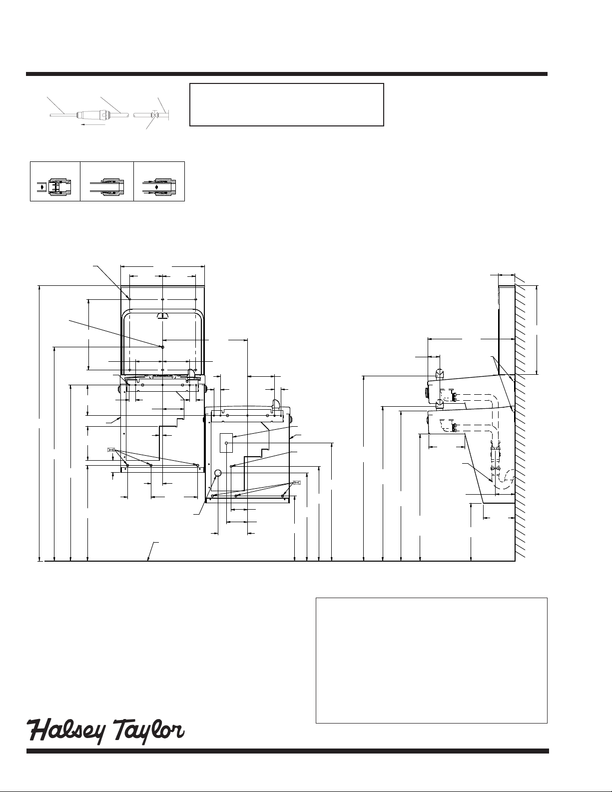
1/4” O.D. TUBE
WATER INLET
TO COOLER
OPERATION OF QUICK CONNECT FITTINGS
OPERATION OF QUICK CONNECT FITTINGS
SIMPLY PUSH IN
SIMPLY PUSH IN
TUBE TO ATTACH
TUBE TO ATTACH
A B C
3/8” O.D. TUBE CONNECT
COLD WATER SUPPLY
NOTE: WATERFLOW
DIRECTION
TUBE IS SECURED
TUBE IS SECURED
IN POSITION
IN POSITION
B CA
BUILDING WATER
SERVICE STOP
(NOT FURNISHED)
PUSH IN COLLET
PUSH IN COLLET
TO RELEASE TUBE
TO RELEASE TUBE
PUSHING TUBE IN BEFORE
PUSHING TUBE IN BEFORE
PULLING IT OUT HELPS TO
PULLING IT OUT HELPS TO
RELEASE TUBE
RELEASE TUBE
FRONT VIEW SIDE VIEW
7/16"
O
11mm
58 9/16"
1488mm
MOUNTING HOLES
ACTIVATION
SENSOR
45 9/16"
1157mm
37 1/2"
952mm
(6)
15"
381mm
5/16" (8mm) DIA.
6 1/2"
165mm
7 1/4"
185mm
20 3/8"
518mm
5 3/4"
146mm
(10 HOLES)
1 3/8"
35mm
E
F
2 9/16"
65mm
4 9/16"
116mm
5"
127mm
7"
178mm
INLET
17 7/8"
454mm
1 3/8"
35mm
C
L
254mm
FINISHED FLOOR
NOTE: A service stop (not included) must be installed at
the water inlet line.
NOTE: P-Trap (not supplied) to be installed per local
building code.
7"
178mm
18 1/16"
459mm
5 3/4"
146mm
11/16"
18mm
2 7/16"
63mm
10"
5 3/4"
146mm
1 3/8"
1 3/8"
35mm
35mm
C
L
B
6 1/4"
159mm
3 1/2"
89mm
4 1/2"
114mm
5 3/4"
146mm
13 7/8"
352mm
D
E
A
F
18 3/4"
476mm
20 1/8"
511mm
25 1/8"
638mm
39 7/16"
1002mm
ORIFICE HEIGHT
ORIFICE HEIGHT
ELECTRICAL
Hydroboost® station equipped with electric cord
and three-prong molded rubber plug for use with
15-amp minimum receptacle. Rated at 115 volt,
60 Hz, single phase.
OPERATING PRESSURES
Supply water - 105 psi maximum
Minimum 40 psi supply line pressure required
in special circumstances where both sides of
bi-level are in use simultaneously to ensure
adequate stream height. Use of water lter in
this situation is not recommended.
3 9/16"
90mm
18 5/8"
472mm
32 15/16"
837mm
2 5/8"
67mm
31 15/16"
811mm
RIM HEIGHT
27"
686mm
ADA
REQURIEMENTS
8"
203mm
105mm
HANGER BRACKET
C
4 1/8"
12 5/16"
313mm
6 3/4"
172mm
18 7/8"
479mm
REDUCE HEIGHT BY 3” FOR INSTALLATION OF CHILDRENS ADA COOLER
LEGEND:
A = Recommended Water Supply Location. Shut-off valve (not furnished) to accept
3/8” O.D. unplated copper tube. Up to 3” (76mm) maximum out from wall.
B = Recommended Waste Outlet location. To accommodate 1-1/2” nominal drain.
Drain stub 2” (51mm) out from wall.
C = 1-1/2” Trap (not furnished).
D = Electrical Supply (3) Wire Recessed Box Duplex Outlet.
E = Insure proper ventilation by maintaining 6” (152mm) minimum clearance from
cabinet louvers to wall.
F = 7/16” (11mm) Bolt Holes for fastening to wall.
**New Installations Must Use Ground Fault Circuit Interrupter (GFCI).
®
Page 2
Job Name: ____________________________________
Model: _____________________________ Qty. ______
Contact: ______________________________________
Approval Signature: _____________________________
Notes:
Printed in the U.S.A.
 Loading...