

Halsey Taylor HTERQ-E Installation Manual
HTERQ*E HTSRQ*E HTESRQ*K HTSERQ*K
HALSEY TAYLOR OWNERS MANUAL
Classic
Refrigerated Fountains with Back Panel
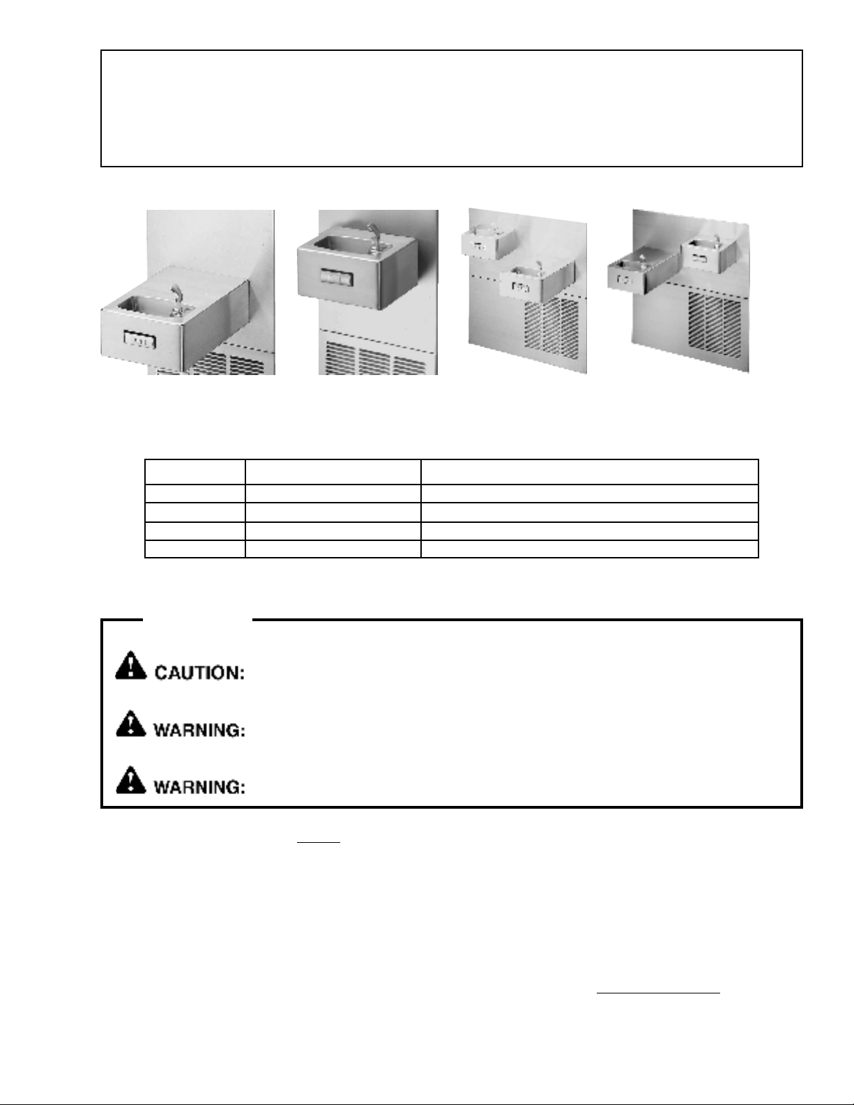
Figure 1 HTER-Q Figure 2 HTSR-Q Figure 3 HTSER-Q Figure 4 HTESR-Q
TM
Series Barrier-Free Water Coolers
Figure
1
2
3
4
Model
HTER-Q
HTSR-Q
HTSER-Q
HTESR-Q
Classic
Classic
Classic
Classic
Description
TM
Series - Extended Reach
TM
Series - Standard Reach
TM
Series - Dual Installation
TM
Series - Dual Installation
INSTALLER
Review these instructions before beginning installation. Be sure that installation
conforms to all plumbing, electrical and other applicable codes.
When installation is complete, ensure these instructions are left in the plastic bag
provided inside the installed unit for future reference.
Service to be performed by authorized service personnel only.
NOTE: It is common practice to ground electrical hardware such as telephones, computers and other devices
to available water lines. This can, however, cause electrical feedback in the plumbing circuit, which
results in an electrolysis effect occurring in the fountain. This may result in water which has a metallic
taste to it or has a noticeable increase in the metallic content of the water.
When inspecting plumbing circuit, remember the line may be grounded some distance from the
installation, and may occur outside the building or area in which the unit is being installed.
This condition can be avoided (in most cases) by using recommended materials during installation. Any
drain fittings provided by the installer should be made of plastic which will electronically isolate the
fountain from the remainder of the buildings plumbing circuits.
97877C (Rev. A 3/04)
1
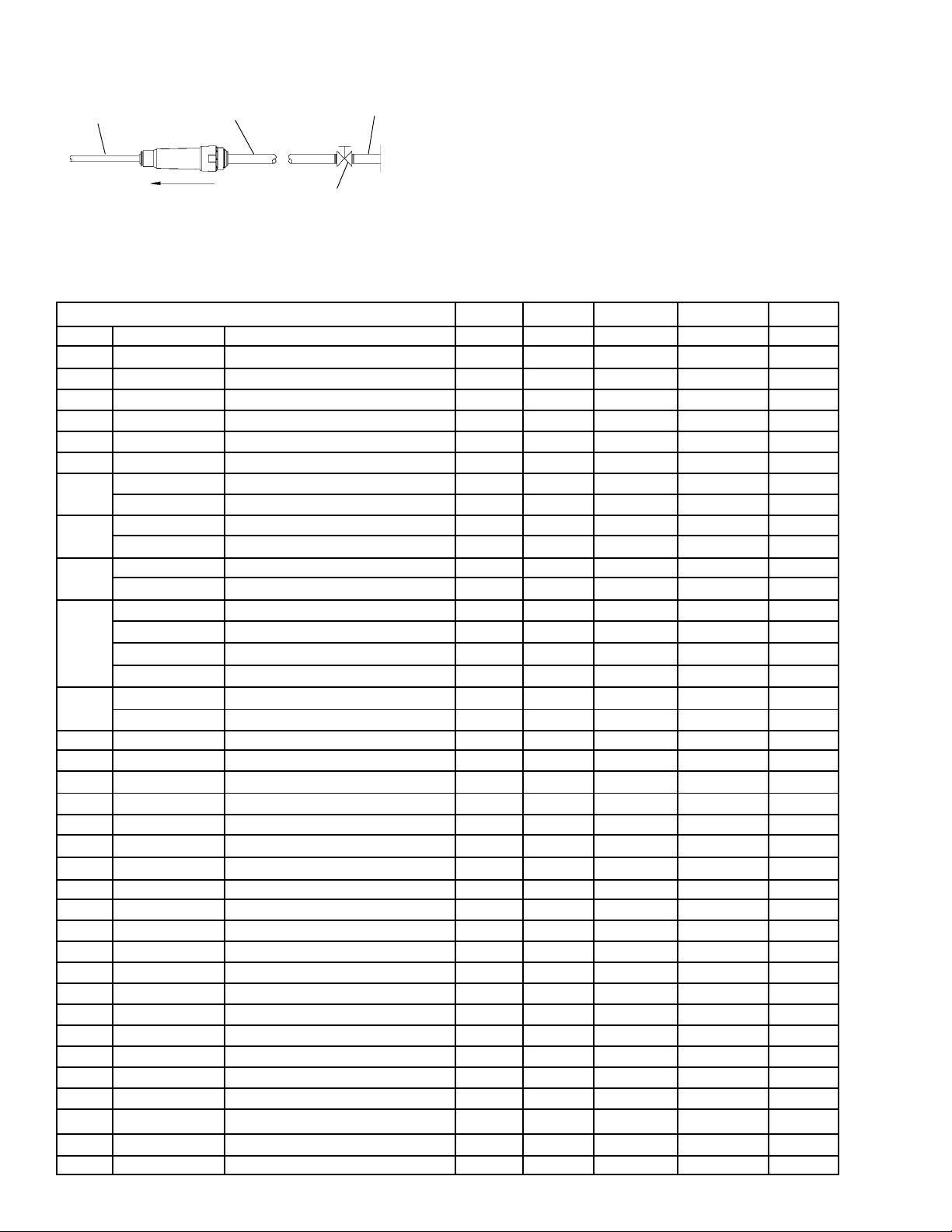
1/4" O.D. TUBE
WATER INLET
TO COOLER
NOTE: WATER FLOW
Figure 5 Water Supply Connections
3/8" O.D. UNPLATED
COPPER TUBE CONNECT
COLD WATER SUPPLY
DIRECTION
HTERQ*E HTSRQ*E HTESRQ*K HTSERQ*K
Installation Package
BUILDING WATER
INLET
SERVICE STOP
(NOT FURNISHED)
The components for installation are packed in three
separate boxes, regardless of the type of unit being
installed. The boxes contain the following:
Box No. 1: Wall Frame(s)
Box No. 2: Remote Chiller, SJ8-Q
Box No. 3: Fountain(s), Arm(s) and Panels
Additional materials, as noted in the Parts List, are also
shipped in these boxes.
Parts List
Item Part No. Description HTER-Q HTSR-Q HTSER-Q See Fig.
1
2
3
4
5
6
7
8
9
10
11
12
13
14
15
16
17
18
19
20
21
22
23
24
25
26
27
28
29
30
31
32
33
97877C (Rev. A 3/04)
51546C
66318C
10080C
100322740560
160270508640
161637308640
100147140560
66346C
66343C
28316C
28317C
23001C
23002C
26837C
26835C
27028C
26839C
26833C
27026C
56121C
75588C
75589C
55996C
70682C
70683C
56092C
26901C
26935C
27237C
75517C
70378C
75555C
75504C
55859C
101514331640
111411743620
40045C
15005C
61313C
50986C
Bubbler
Bubbler Tube Assembly
Bubbler Nipple (Included w/Item 2)
Bubbler Gasket
Strainer Plate
Drain Plug
Drain Gasket
Waste Tube (HT-ER)
Waste Tube (HT-SR)
Basin - Stainless Steel (HT-ER)
Basin - Stainless Steel (HT-SR)
Bottom Cover (HT-ER)
Bottom Cover (HT-SR)
Upper Panel (HT-ER)
Upper Panel (HT-SR)
Upper Panel (HT-ESR)
Upper Panel (HT-SER)
Lower Panel (HT-ER/SR)
Lower Panel(HT-ESR/SER)
Drain Elbow
Nut - 1-1/4 Slip Joint
Washer - Seal
Strainer (Supplied with Chiller)
Tee - 1/4
Union - 1/4
Poly Tubing (Cut To Length)
Push Lever
Mounting Bracket Assy
Bracket - Pushbar
Lever Rod
Pushbar Rod
Spring Clip
Screw - #10-24 x .38 PHMS
Pushbar - Side & Front
Pushbar Insert
Nut - 1/4 Self Thread
Regulator Hex Nut
Regulator Retaining Nut
Regulator
Regulator Holder
1
1
1
2
1
1
1
1
-
1
-
1
-
1
-
-
-
1
1
1
1
1
1
1
1
1
1
1
1
1
1
1
1
2
1
1
1
1
Number RequiredNumber Required
HTESR-Q
1
1
1
2
1
1
1
-
1
-
1
-
1
-
1
-
-
1
1
1
1
1
1
1
1
1
1
1
1
1
1
1
1
2
1
1
1
1
2
2
2
4
2
2
2
1
1
1
1
1
1
-
-
1
-
1
2
2
2
1
1
1
2
2
2
2
2
4
2
2
2
4
2
2
2
2
2
2
2
4
2
2
2
1
1
1
1
1
1
-
-
-
1
1
2
2
2
1
1
1
2
2
2
2
2
4
2
2
2
4
2
2
2
2
17, 18
18
18
18
18
18
18
18
18
18
18
18
18
18
18
18
18
18
18
18
18
18
5, 19, 20
20
19
19, 20
15
15
15
15
15
15
15
15
15
15
15
15
15
15
2
HTERQ*E HTSRQ*E HTESRQ*K HTSERQ*K
Item Part No. Description
34
35
36
37
NS
50198C
55899C
27073C
70055C
112627543890
Snap Bushing
Pad - Window Filler
Backing Plate
Speed Nut
Screw 10-24 x 1/2 PHTC
HTER-Q HTSR-Q HTSER-Q See Fig.HTESR-Q
10
8
1
1
1
8
1
1
1
10
16
2
2
2
20
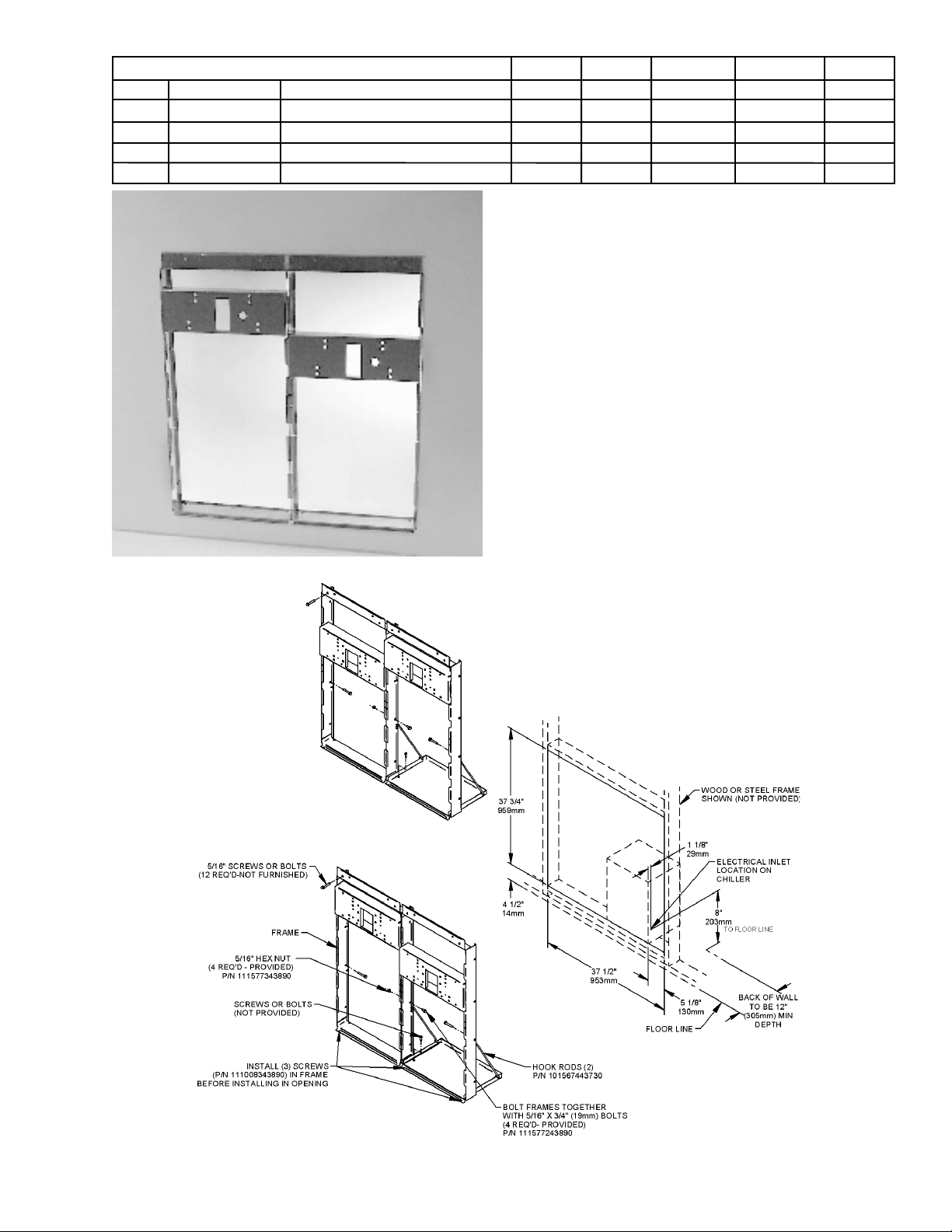
1. Cut a rectangular wall opening 37-1/2 (953 mm) W x
37-3/4 H (959 mm) and 4-1/2 (114 mm) above the
floor line (see Figure 7). The dimensions are required
to obtain proper rim and bubbler heights for
compliance with ANSI standard A117.1.
2. Reinforce the wall opening on all sides to adequately
support the water fountain. This reinforcement must
support up to 150 lbs. static load and provide a
means for securing the frame assembly in place.
NOTE: Building construction must allow for
adequate air flow on both sides and top of
remote chiller unit a minimum of 4 (102
mm) is required. See chiller installation for
additional instructions.
16
20
15
2
2
2
15
15
15
-
Figure 6 HTSER-Q Rough-In
REVERSED CONFIGURATION:
HIGHER UNIT ON THE RIGHT
3. Install plumbing and electrical rough-ins. A junction
box for a (3) wire, 10 amp branch circuit is provided on
the inside of the chiller. (Standard 120 Volts, 60 Hz,
and single phase.)
4. Remove frames and related hardware from
packaging. Release the two shelf rods by cutting
cable ties. Attach the two frames together through the
upright supports with (4) 5/16 x 3/4 (19 mm) long
bolts and nuts (provided). Tighten securely.
MAKE SURE FRAME CONFIGURATION MATCHES
THE COOLER TO BE INSTALLED
STANDARD CONFIGURATION:
HIGHER UNIT ON THE LEFT
Figure 7 Rough-In Assembly
Dual-Station Mounting Frames
3
97877C (Rev. A 3/04)
 Loading...