

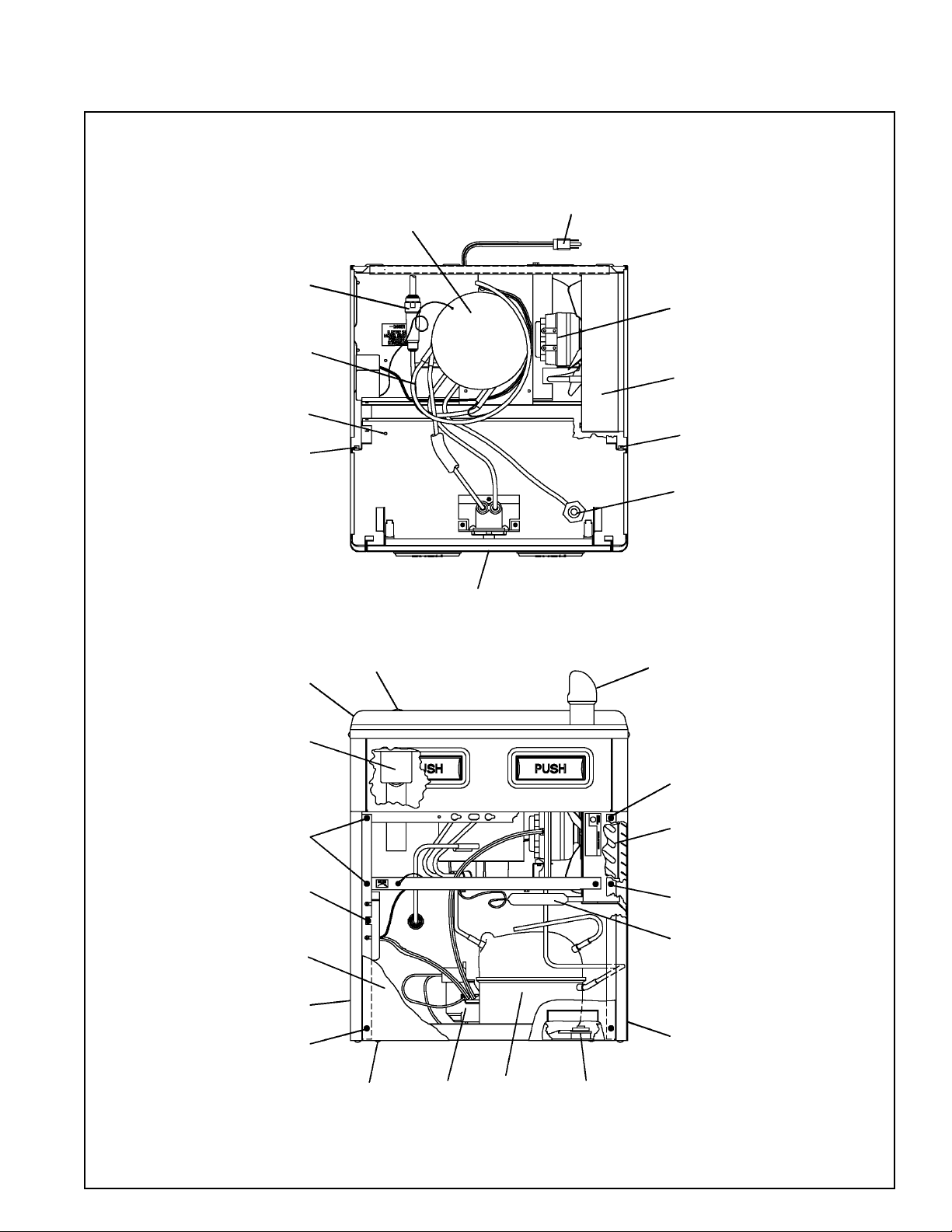
HOWC8F-Q*1B
HALSEY TAYLOR OWNERS MANUAL
USES HFC-134A REFRIGERANT
18
49
53
19,20,21,22
41
23,24
17
25
25
46
42,43,44,
45,51,52
50
26,48
34
47
27
See Fig. 3 (on Page 3)
For Push Bar Mechanism
28,29
50
30
50
31
33
50
17
39,40,
55
38
Page 1
32
35,36,37
97356C (REV A - 2/01)
HOWC8F-Q*1B
length of cooler waste line before connecting to trap (see installation instruction No.7)
cortar 1½ pulgadas del largo del tubo de desagüe del enfriador antes de conectar el purgador
(vea las instrucciones de instalación No. 7)
pouce de longueur de la canalisation résiduaire du refroidisseur avant de le raccorder au siphon
*ADA REQUIREMENT
*REQUISITO DE A.D.A.
*EXIGENCE ADA
**When replacing a Model BFC with a new unit Model HAC, installer must cut 1-1/2 inches from
**Cuando reemplace un Modelo BFC con una unidad nueva Modelo HAC el instalador deberá
(voir instruction dinstallation no. 7)
**En remplaçant un modèle BFC avec un nouveau modèle HAC, linstallateur doit couper 1 1/2
97356C (REV A - 2/01)
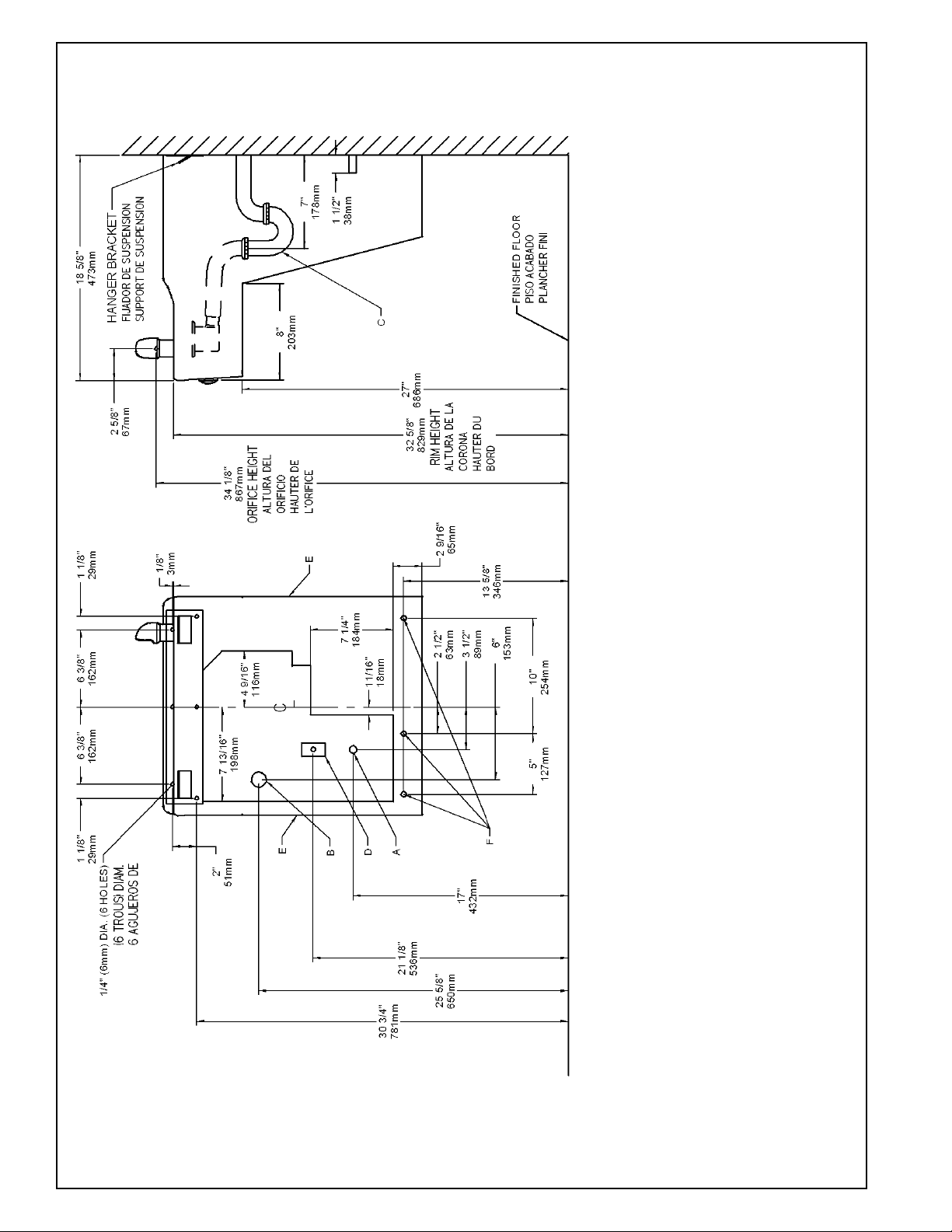
FIG. 2
Page 2
OFF BY OTHERS
DE LA LLAVE DE PASO EN LA PARED COLOCADA POR TERCEROS.
TUYAUTERIE DE 1-1/2 PO. (38 mm) DEPUIS LE ROBINET D'ARRÊT FOURNI PAR D'AUTRES.
UBICACIÓN RECOMENDADA PARA EL DRENAJE DE SALIDA DE AGUA, DE 1¼ DE DIÁMETRO.
SE RECOMIENDA UBICAR EL TUBO CORTO DE CONEXIÓN AL TUBO DE COBRE SIN CHAPAR DE 3/8" DE DIÁM. EXT. A 1-1/2" (38 mm) FUERA
LEGEND/LEYENDA/LÉGENDE
A = RECOMMENDED WATER SUPPLY LOCATION 3/8 O.D. UNPLATED COPPER TUBE CONNECT STUB 1-1/2 IN. (38 mm) OUT FROM WALL SHUT
EMPLACEMENT RECOMMANDÉ POUR LE DRAIN DE D.E. 1-1/4" DE SORTIE DEAU.
EMPLACEMENT RECOMMANDÉ D'ALIMENTATION EN EAU PAR TUBE EN CUIVRE NON PLAQUÉ DE 3/8 PO. (9,5 mm) D.E. CONNECTANT UNE
B = RECOMMENDED LOCATION FOR WASTE OUTLET 1-1/4 O.D. DRAIN
C = 1-1/4 TRAP NOT FURNISHED**
PURGADOR DE 1¼ NO PROPORCIONADO**
SIPHON 1-1/4 NON FOURNI**
CAJA RECESIVA DE ALAMBRES (3) DE SUMINISTRO ELÉCTRICO
BOÎTE ENCASTRÉE DALIMENTATION ÉLECTRIQUE (3) FILS
ASEGURE UNA VENTILACIÓN ADECUADA MANTENIENDO UN ESPACIO E 6" (152 mm) (MÍN.) DE HOLGURA ENTRE LA REJILLA DE
VENTILACIÓN DEL MUEBLE Y LA PARED
ASSUREZ-VOUS UNE BONNE VENTILATION EN GARDANT 6" (152 mm) (MIN.) ENTRE LES ÉVENTS DE LENCEINTE ET LE MUR.
AGUJEROS DE LAS TUERCAS DE 7/16 PARA SUJETAR LA UNIDAD A LA PARED
TROUS DÉCROUS 7/16 POUR FIXER LAPPAREIL AU MUR
D = ELECTRICAL SUPPLY (3) WIRE RECESSED BOX WITH GROUND FAULT CIRCUIT INTERRUPTER (GFCI)
E = INSURE PROPER VENTILATION BY MAINTAINING 6" (152 mm) (MIN.) CLEARANCE FROM CABINET LOUVERS TO WALL.
F = 7/16 BOLT HOLES FOR FASTENING UNIT TO WALL

HOWC8F-Q*1B
PUSH BAR MECHANISM
11
12
13
14
5
10
3
9
A
1
15
2
6
7
8
10
Water Valve Mechanism - ADJUSTMENT PROCEDURE:
- Turn adjustment screw (Item 16) Counter-Clockwise until water flow from
bubbler starts.
- Turn adjustment screw Clockwise until water flow stops, THEN turn an
additional 1/2 turn.
NOTE: Adjustments stated above are viewed from underneath unit (bottom side of
dispenser panel Item 1)
NOTE: If continuous flow occurs at the end of the compressor cycle, turn cold
control (Item 48) counterclockwise 1/4 turn.
ALL SERVICE TO BE PERFORMED BY AN
AUTHORIZED SERVICE PERSON
1) Remove hanger bracket fastened to back of cooler by removing
one (1) screw.
2) Mount the hanger bracket and trap as shown in Figure 2.
NOTE: Hanger Bracket MUST be supported securely. Add fixture sup-
port carrier if wall will not provide adequate support.
IMPORTANT:
7 in. (178mm) dimension from wall to centerline of trap must be
maintained for proper fit.
Anchor hanger securely to wall using all six (6) 1/4 in. dia. mounting
holes.
3) Install straight valve for 3/8" O.D. tube.
4) Hang the cooler on the hanger bracket. Be certain the hanger bracket
is engaged properly in the slots on the cooler back as shown in Fig.
4.
5) Loosen the two (2) screws holding the lower front panel at the bottom of cooler base and two (2) screws at the top. Remove the front
panel and set aside.
6) Connect water inlet line--See Note 4 of General Instructions.
7) Remove the slip nut and gasket from the trap and install them on the
cooler waste line making sure that the end of the waste line fits into
the trap. Assemble the slip nut and gasket to the trap and tighten
securely.
8) Stream height is factory set at 45-50 PSI. If supply pressure
varies greatly from this, readjust stream height to approximately 1-1/2" (38mm) above the bubbler guard by turning adjustment screw, accessible by removing front push panel,Item
No.6 (see Fig. 3).
9) Connect to electrical supply with a ground fault circuit
interrupter (GFCI) installed.
10) Replace the front panel and secure by retightening four (4)
screws.
11) If a taste, odor or sediment problem is prevalent, try installing
our water filter module, part no 73-15242-51-550
12) If the ambient air temperature drops below freezing, the cooler
needs to be drained of all water by blowing out all water lines,
evaporator (Item #49) and the drain trap.
IMPORTANT
HANGER BRACKETS & TRAP
INSTALLATION
INSTALLATION OF COOLER
START UP
Also See General Instructions
PROTECT FROM FREEZING
10
17
16
B
C
LEGEND
A) Note: Water flow direction
B) Adjust this screw to eliminate mechanism Free Play or continuous flow
from bubbler conditions. (See ADJUSTMENT PROCEDURE)
C) Stream height adjustment (see note #8)
54
4
FIG. 3
HANGER BRACKET
FIJADOR DE SUSPENSIÓN
SUPPORT DE SUSPENSION
COOLER BACK
SUPPORT DE SUSPENSION
ARRIÈRE DU REFROIDISSEUR
FIG. 4
Page 3
97356C (REV A - 2/01)

ITEMIZED PARTS LIST
ITEM
*REPLACE WITH SAME COMPRESSOR USED IN ORIGINAL ASSEMBLY.
NOTE: All correspondence pertaining to any of the above water coolers or
orders for repair parts MUST include Model No. and Serial No. of cooler, name and
part number of replacement part.
NO
38*
NS
NS
NS
1
2
3
4
5
6
7
8
9
10
11
12
13
14
15
16
17
18
19
20
21
22
23
24
25
26
27
28
29
30
31
32
33
34
35
36
37
39
40
41
42
43
44
45
46
47
48
49
50
51
52
53
54
55
PART NO
22897C
51531C
11-14117-43-620
22822C
22814C
22806C
55859C
10-15143-31-640
22900C
75499C
40045C
23003C
15005C
61314C
50986C
70935C
75500C
35870C
30699C
70018C
31490C
70009C
22899C
38417001
75524C
27124C
15008C
45392C
75564C
62152C
66202C
22862C
22854C
22955C
10-15161-43-550
10-08067-40-570
19037000
35947C
31039C
35768C
66532C
45351C
10-01471-40-560
10-26399-31-640
16-02705-08-640
22893C
10-06876-08-640
31513C
66534C
70002C
55884C
55885C
55996C
55931C
35935C
40-06609-43-730
75519C
75520C
Panel - Bottom Dispenser
Block - Pivot
Nut - 1/4 , Self-Threading
Panel - Right Side
Panel - Left Side
Panel - Front Push
Pushbar - Side & Front
Insert - Push Bar, Chrome
Bracket - Front Push
Screw #8 x 5/8" Lg. Torx
Hex Nut
Bracket - Regulator Mounting
Retaining Nut
Regulator
Holder - Regulator
Screw - Shoulder x 1/2" Lg.
Screw #10 x 1/2" Lg. Torx
Power Cord
Fan Blade
Hex Nut - Fan Blade
Fan Motor
Screw - (Fan Motor)
Shroud - Fan
Screw - #8-18 x 3/8" Lg. (Fan Shroud)
Clip (Front and Rear Panels)
Cover - Cold Control
Bubbler Nipple Assy
Bubbler
Washer - Locking
Condenser
Drier
Panel - Right Rear
Panel - Left Rear
Panel - Front Lower
Stud - Compressor Mtg.
Grommet - Compressor Mtg.
Clip - Compressor Mtg.
Compressor Serv. Pak EM65
Overload/Relay P600B/427NFBYY
Cover - Relay
Heat Exchanger
Waste Line
Gasket - Drain
Drain Plug
Strainer Plate
Basin
Plug Button
Cold Control
Evaporator Assembly
Screw - #10 x 1/2" Lg. HHSM
Elbow-Drain
Nut 1-1/4 Slip Joint
Strainer
Cover - Dispenser Bottom
Capacitor - Run
Hanger Bracket
Bit-Pinned Torx T-15
Bit-Pinned Torx T-25
DESCRIPTION
HOWC8F-Q*1B
2222 CAMDEN COURT
OAK BROOK, IL 60523
630.574.3500
PRINTED IN U.S.A.
97356C (REV A - 2/01)
FOR PARTS, CONTACT YOUR LOCAL DISTRIBUTOR OR CALL 1.800.323.0620
Page 4
 Loading...