

HAC8EEBLQ*1F , HAC8EEBLRQ*1F
HALSEY TA YLOR OWNERS MANUAL
USES HFC-134A REFRIGERANT
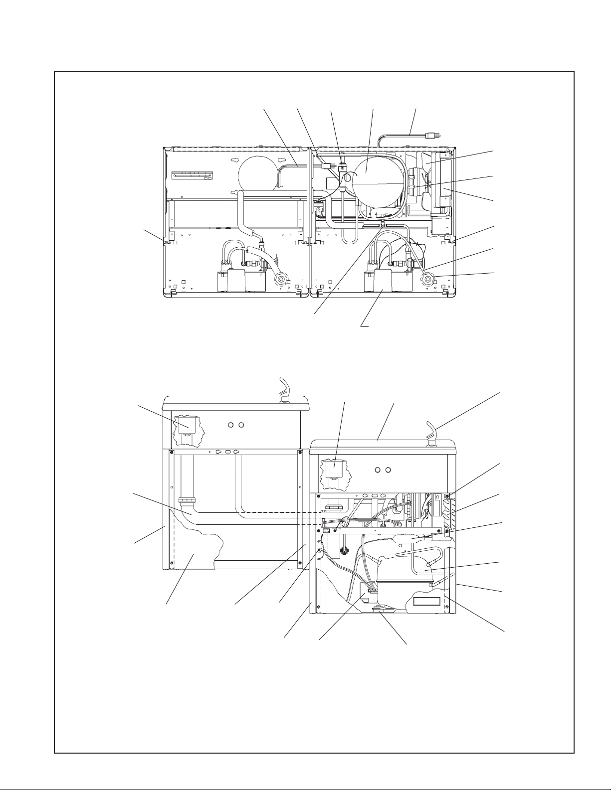
25
59
43
60
57
54
See Fig. 3 (on Page 3)
For Electric Eye Mechanism
18
19,20
21,22
23
25
24
26
45,46,47,48,
49,58,52
55
16
14
15
53
17
44
40,41,42
50,51
36,37,38
27,28
35
29
30
39
13
14
Page 1
98145C (3/05)
HAC8EEBLQ*1F , HAC8EEBLRQ*1F
cooler waste line before connecting to trap (see installation instruction No.7)
1½ pulgadas del largo del tubo de desagüe del enfriador antes de conectar el purgador (vea las
instrucciones de instalación No. 7)
de longueur de la canalisation résiduaire du refroidisseur avant de le raccorder au siphon (voir
*ADA REQUIREMENT
*REQUISITO DE A.D.A.
*EXIGENCE ADA
**When replacing a Model “BFC” with a new unit Model “HAC”, installer must cut 1-1/2 inches from length of
**Cuando reemplace un Modelo “BFC” con una unidad nueva Modelo “HAC” el instalador deberá cortar
instruction d’installation no. 7)
**En remplaçant un modèle “BFC” avec un nouveau modèle “HAC”, l’installateur doit couper 1 1/2 pouce
98145C (3/05)
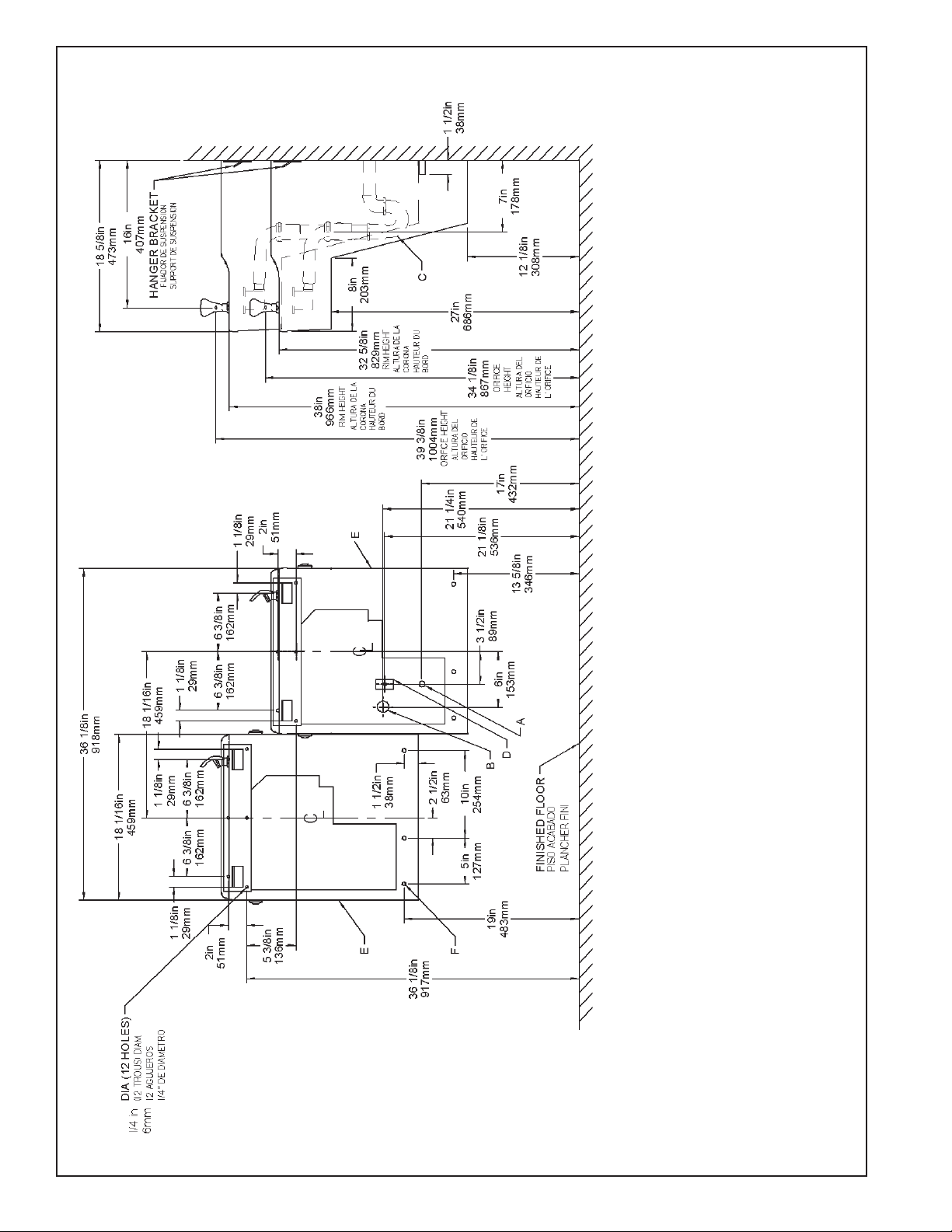
FIG. 2
Page 2
OFF BY OTHERS
DE LA LLA VE DE P ASO EN LA PARED COLOCADA POR TERCEROS.
TUYAUTERIE DE 1-1/2 PO. (38 mm) DEPUIS LE ROBINET D'ARRÊT FOURNI P AR D'AUTRES.
UBICACIÓN RECOMENDADA P ARA EL DRENAJE DE SALIDA DE AGUA, DE 1-1/2” DE DIÁMETRO.
SE RECOMIENDA UBICAR EL TUBO COR TO DE CONEXIÓN AL TUBO DE COBRE SIN CHAP AR DE 3/8" DE DIÁM. EXT. A 1-1/2" (38 mm) FUERA
LEGEND/LEYENDA/LÉGENDE
A = RECOMMENDED WA TER SUPPLY LOCATION 3/8 O.D. UNPLA TED COPPER TUBE CONNECT STUB 1-1/2 IN. (38 mm) OUT FROM WALL SHUT
EMPLACEMENT RECOMMANDÉ POUR LE DRAIN DE D.E. 1-1/2" DE SORTIE D’EAU.
EMPLACEMENT RECOMMANDÉ D'ALIMENTA TION EN EAU P AR TUBE EN CUIVRE NON PLAQUÉ DE 3/8 PO. (9,5 mm) D.E. CONNECT ANT UNE
B = RECOMMENDED LOCATION FOR W ASTE OUTLET 1-1/2” O.D. DRAIN
C = 1-1/2 TRAP NOT FURNISHED**
PURGADOR DE 1-1/2 NO PROPORCIONADO**
SIPHON 1-1/2 NON FOURNI**
CAJA RECESIV A DE ALAMBRES (3) DE SUMINISTRO ELÉCTRICO
BOÎTE ENCASTRÉE D’ALIMENTA TION ÉLECTRIQUE (3) FILS
ASEGURE UNA VENTILACIÓN ADECUADA MANTENIENDO UN ESP ACIO E 6" (152 mm) (MÍN.) DE HOLGURA ENTRE LA REJILLA DE
VENTILACIÓN DEL MUEBLE Y LA P ARED
ASSUREZ-VOUS UNE BONNE VENTILATION EN GARDANT 6" (152 mm) (MIN.) ENTRE LES ÉVENTS DE L ’ENCEINTE ET LE MUR.
AGUJEROS DE LAS TUERCAS DE 7/16 PARA SUJET AR LA UNIDAD A LA P ARED
TROUS D’ÉCROUS 7/16 POUR FIXER L’APP AREIL AU MUR
D = ELECTRICAL SUPPLY (3) WIRE RECESSED BOX
E = INSURE PROPER VENTILATION BY MAINTAINING 6" (152 mm) (MIN.) CLEARANCE FROM CABINET LOUVERS TO WALL.
F = 7/16 BOLT HOLES FOR FASTENING UNIT TO WALL

HAC8EEBLQ*1F , HAC8EEBLRQ*1F
PUSH BAR MECHANISM
RANGE
ADJUSTMENT
SCREW
33
3
6
32
7
32
11
Sensor Control: If sensor fails to operate valve mechanism or operates erratically,
check the following.
a. Ensure there are no obstructions within a 40-inch radius from front of cooler.
b. Check wire connections at solenoid valve and sensor.
CAUTION: Make sure unit is unpluged before checking any wiring.
c. Ensure proper operation of solenoid valve. If there is an audible clicking sound yet
no water flows, look for an obstruction in the valve itself or elsewhere in the water
supply line.
NOTE: WATER FLOW DIRECTION
34
31
10
8
9
35
9
1
5
32
4
56
2
12
Sensor Range Adjustment: The electronic sensor used in this cooler is factory pre-
set for a "visual" range of 36 inches. If actual range varies greatly from this, or a
different setting is desired, follow the range adjustment procedure below:
a. Remove front panel of cooler.
b.Using a small tip screwdriver, rotate range adjustment screw clockwise to increase
range and counter-clockwise to decrease range. (See Fig. 3).
CAUTION: Complete range of sensor (24-46 inches) is only one turn of the
adjusting screw.
c. Replace the front panel.
FIG. 3
ALL SERVICE TO BE PERFORMED BY AN
AUTHORIZED SERVICE PERSON
CAUTION: To preserve the quality and keep this AZTEC GOLD
finish clean and spot free, clean this surface with only mild
detergent or window cleaner and polish with a soft cloth.
DO NOT use any abrasive cleaners or harsh chemicals.
They WILL damage the finish!
1) Remove hanger bracket fastened to back of cooler by removing
one (1) screw.
2) Mount the hanger bracket and trap as shown in Figure 2.
NOTE: Hanger Bracket MUST be supported securely. Add fixture sup-
port carrier if wall will not provide adequate support.
IMPORTANT:
y 7 in. (178mm) dimension from wall to centerline of trap must be
maintained for proper fit.
y Anchor hanger securely to wall using all six (6) 1/4 in. dia. mounting
holes.
3) Install straight valve for 3/8" O.D. tube.
4) Hang the cooler on the hanger bracket. Be certain the hanger bracket
is engaged properly in the slots on the cooler back as shown in Fig.
4.
5) Loosen the two (2) screws holding the lower front panel at the bottom of cooler base and two (2) screws at the top. Remove the front
panel and set aside.
6) Connect water inlet line--See Note 4 of General Instructions.
7) Remove the slip nut and gasket from the trap and install them on the
cooler waste line making sure that the end of the waste line fits into
the trap. Assemble the slip nut and gasket to the trap and
tighten securely. Plug both power cords into duplex receptacle.
8) Stream height is factory set at 45-50 PSI. If supply pressure varies
greatly from this, readjust stream height to approximately 1-1/2"
(38mm) above the bubbler guard by turning adjustment screw, accessible by removing front panel,Item No.7 (see Fig.3 & 5).
9) Replace the front panel and secure by retightening four (4)
screws.
IMPORTANT
HANGER BRACKETS & TRAP
INSTALLATION
INSTALLATION OF COOLER
START UP
Also See General Instructions
HANGER BRACKET
FIJADOR DE SUSPENSIÓN
SUPPORT DE SUSPENSION
COOLER BACK
SUPPORT DE SUSPENSION
ARRIÈRE DU REFROIDISSEUR
CORRECT STREAM HEIGHT
FIG. 4
FIG. 5
Page 3
98145C (3/05)

HAC8EEBLQ*1F , HAC8EEBLRQ*1F
ITEM
NO
1
2
3
4
5
6
7
8
9
10
11
12
13
14
15
16
17
18
19
20
21
22
23
24
25
26
27
28
29
30
31
32
ITEMIZED P ARTS LIST
PART NO
22897C
26729C
36028C
31272C
See Color T able
See Color T able
See Color T able
70817C
75507C
56082C
70644C
75497C
See Color T able
See Color T able
See Color T able
See Color T able
See Color T able
31483C
30664C
70018C
31490C
70009C
56237C
56092C
75524C
56159C
51544C
45396C
55905C
100322740560
66743C
66703C
61314C
70864C
Panel - Bottom Dispenser
Bracket - Valve Mounting
Sensor - Clear (115V)
Solenoid Valve (1 15V)
Panel - Right Side
Panel - Left Side
Panel - Front
Elbow 1/4 Stem x 1/4 O.D.
Fitting 1/4 NPTF x 1/4 O.D.
Nut - Regulator
Screw #6-32 x 1/2" Lg. PHMS
Screw #10 x 1/2" Lg. PHSM
Panel - Right Rear (Refrig. Unit)
Panel - Front Lower
Panel - Right Rear (Left Unit)
Panel - Left Rear (Left Unit)
Panel - Left Rear (Refrig. Unit)
Power Cord
Fan Blade
Hex Nut - Fan Blade
Fan Motor
Screw - (Fan Motor)
Shroud - Fan
Tubing - Poly (Cut To Length)
Clip (Front and Rear Panels)
Nipple - Bubbler
Bubbler - Chrome
Bubbler - Aztec Gold
Bubbler - Flexible (Optional)
Gasket - Bubbler (upper and lower)
Condenser
Drier
Regulator
Screw #8 x 5/8" Lg. Torx/Slot
DESCRIPTION
ITEMIZED P ARTS LIST
ITEM
NO
33
34
35
36
37
38
39*
40
41
42
43
44
45
46
47
48
49
50
51
52
53
54
55
56
57
58
59
60
NS
PART NO
40045C
50986C
70002C
101516143550
100806740570
19037000
36094C
35959C
35768C
36158C
66576C
45351C
56121C
75588C
100147140560
102639931640
45413C
160270508640
45400C
28152C
27594C
75634C
75605C
75589C
31513C
66534C
40022C
See Color T able
55996C
45485C
31376C
70682C
400660943730
Hex Nut
Holder - Regulator
Screw #10 x 1/2" Lg. HHSM
Stud - Compressor Mtg.
Grommet - Compressor Mtg.
Clip - Compressor Mtg.
Compressor Serv. Pak EMI 70 HNR
Relay
Cover - Relay
Overload
Heat Exchanger
Waste Line Assembly
Fitting - Elbow 1-1/4
Nut - Slip Joint 1-1/4
Gasket - Drain
Drain Plug - Chrome
Drain Plug - Aztec Gold
Strainer Plate - Chrome
Strainer Plate - Aztec Gold
Basin - Stainless Steel
Basin - Aztec Gold
Screw - Basin Mtg. - Stainless Steel
Screw - Basin Mtg. - Aztec Gold
Gasket
Cold Control
Evaporator Assembly
Waste Line Assembly
Cover - Dispenser Bottom
Strainer
Waste Line Assembly
Power Cord
Fitting - Tee 1/4
Hanger Bracket
*REPLACE WITH SAME COMPRESSOR USED IN ORIGINAL ASSEMBL Y.
NOTE: All correspondence pertaining to any of the above water coolers
or orders for repair parts MUST include Model No. and Serial No. of cooler ,
name and part number of replacement part.
DESCRIPTION
PANEL
COLOR
Platinum Vinyl
Almond Vinyl
Aztec Gold
Stainless Steel
Item No. 5
Part No.
22820C
23016C
27899C
22822C
Item No. 6
Part No.
22812C
23009C
27897C
22814C
COLOR T ABLE
Item No. 7
Part No.
23135C
23162C
27907C
23137C
Item No. 13
Part No.
22860C
22968C
27911C
22862C
Item No. 14
Part No.
22844C
22954C
27905C
22955C
WIRING DIAGRAM
This Drawing is merely for illustrating the
components of the electrical system.
Item No. 15
Part No.
26806C
26772C
27903C
26776C
Item No. 16
Part No.
22852C
22961C
27909C
22854C
Item No. 17
Part No.
26798C
26765C
27901C
26800C
Item No. 56
Part No.
55931C
55931C
55930C
55931C
2222 CAMDEN COURT
OAK BROOK, IL 60523
630.574.3500
PRINTED IN U.S.A.
98145C (3/05)
REPAIR SERVICE INFORMATION TOLL FREE NUMBER 1.800.260.6640
FOR PARTS, CONTACT YOUR LOCAL DISTRIBUTOR OR VISIT OUR WEBSITE WWW.HALSEYTAYLOR.COM
Page 4
 Loading...