

Chiller Replacement Kit
This Chiller Replacement Kit is used to replace Halsey T aylor T ube on Tube Chiller Coils. Refer to the
following table for identification of the correct replacement kit number.
Replacement Kit P/N
97441C
97442C
97443C
Replaces P/N
66324C, 601548851550
66325C, 601548951550
66326C, 66327C, 601549051550,
601552851550
Unit Type
SW 4, SCWT 4, S300-2D
S500-5D, SW8, WM 8, SCWT 8
S1000-10D, SW 14, WM 14, WM 16,
SCWT14, SCWT 20, HOF 14, XP 8
W ARNING
Installation of this service kit requires sheet metal modification, refrigeration service expertise including brazing, freon recovery
and recharging. All service work must be performed by a qualified service technician. Do not attempt this
replacement if you do not fully understand these requirements. This tank replacement kit will require one or more of the
following steps:
- Brazing of refrigerant and water line (copper) connections
- Revising the mounting system on the cooler shelf including
drilling holes.
- Revising refrigeration line shape and routing
- Revising refrigeration system line hook-ups
- Revising water line sizes
- Revising water line shapes and routings
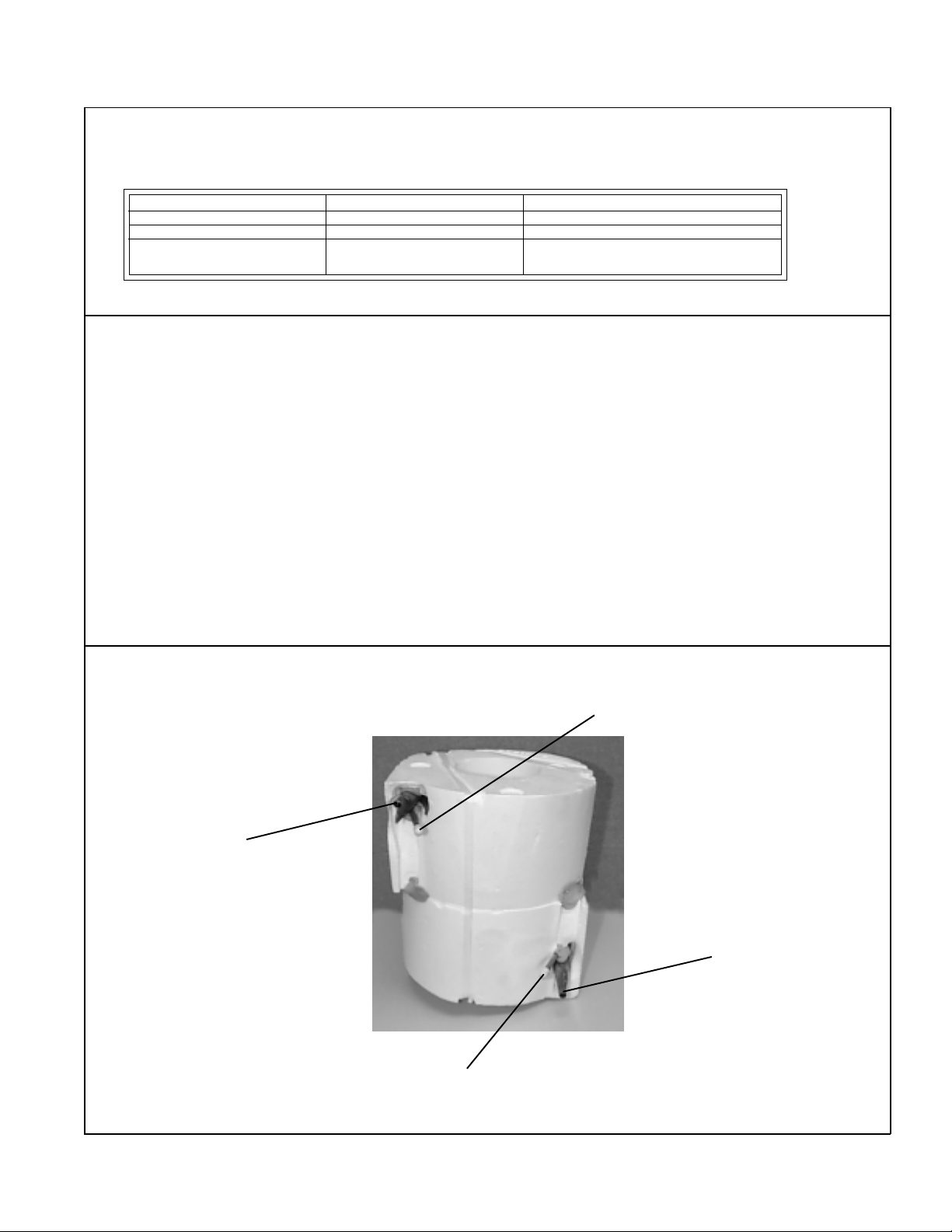
Reference Information
Tube on Tube Chiller
(Original T ank)
Water Outlet
(Large Tube)
Refrigerant Outlet
(Suction Line)
Refrigerant Inlet
(Cap Tube)
Water Inlet
(Large Tube)
FIG. 1
PAGE 1
97444C - 10/98
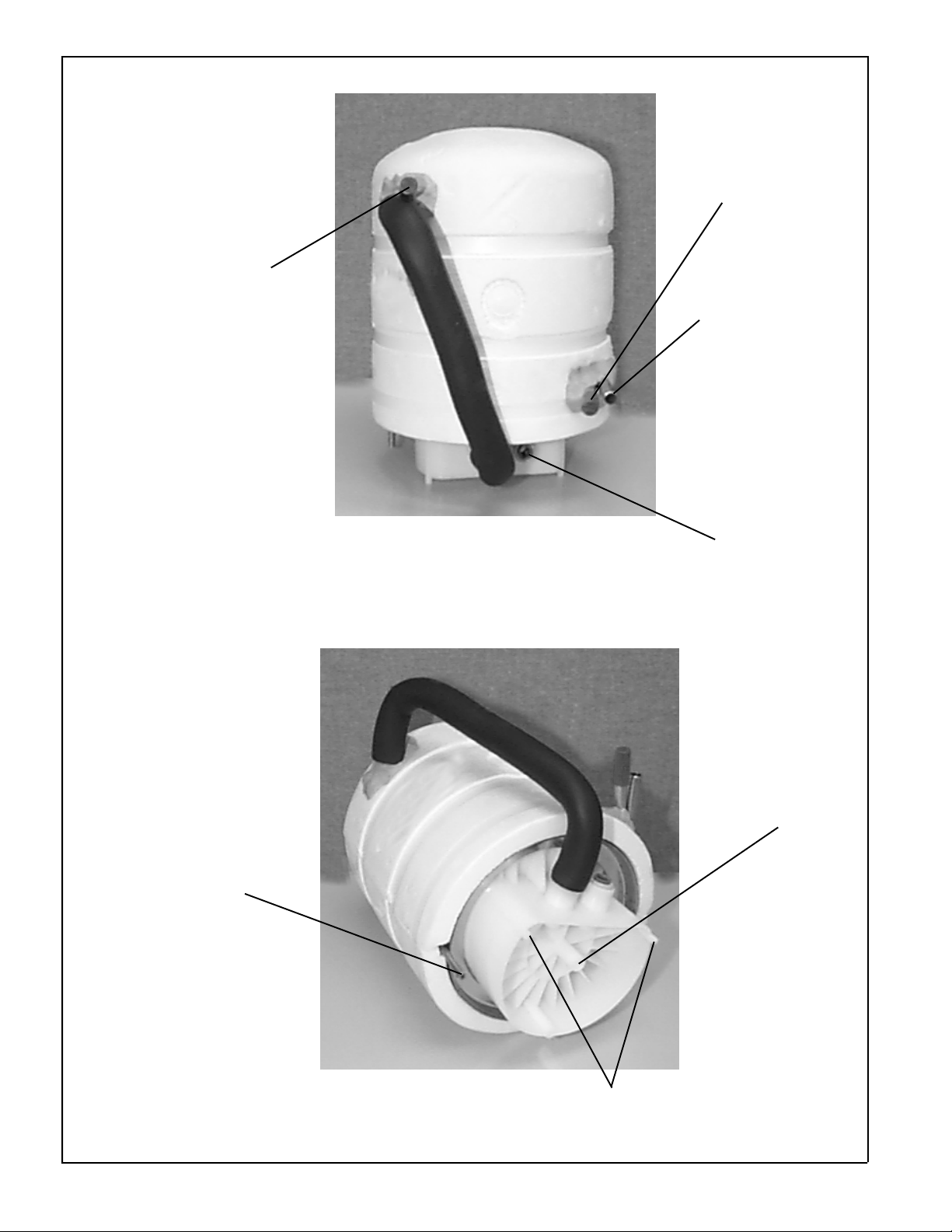
Reference Information
Chiller tank
Refrigerant Outlet
(Suction Line)
Refrigerant Inlet
(Cap Tube)
Water Inlet Tube/
Outside Tube
(Solder Connection)
Water Outlet
(Quick Connect
Fitting)
Thermostat
Bulbwell
97444C - 10/98 PAGE 2
Mounting Boss
Locating Pegs
FIG. 2

Installation Procedure
1. Remove original chiller
2. Refer to location reference guides on page 4 and full size template Part No. 97448C. Locate full size
template per reference guide for model being serviced. Drill Chiller Tank mounting holes.
3. Mount chiller tank to shelf with mounting screw and washer.
4. Revise size of the Refrigerant suction line to adapt to the Refrigerant Outlet on the Chiller Tank.
Reshape the suction line as required. Braze connect the Suction Line to the Refrigerant Outlet.
5. Insert the capillary tube into the Refrigerant Inlet. Pinch the Refrigerant Inlet Line around the
capillary tube and braze connect.
6. Connect the water inlet line into the Chiller Tank W ater Inlet. Revise the water tube size and
routing shape as required. Braze connect the water inlet line connection.
7. Revise the water outlet line to a ¼” tube connection. The ¼” tube connection must be round
and free of surface defects (solder, cuts, etc.). Any surface defects will obstruct the ability of
the quick connect fitting to seal. Insert the straight end of the ¼” tube into the quick connect
connection. Refer to figure 4 for details on how the Guest connection functions.
8. Insert thermostat cap tube into the Chiller Tank bulbwell.
9. Check all connection points for leaks. Repair as required.
10. Recharge the unit and return to service.
FIG. 3
PARTS LIST
1
2
3
1
3
EV APORA TOR T ANK
SCREW #12 X 1.50” LONG
WASHER - .250” I.D.
2
FIG. 4
97444C - 10/98PAGE 3

“S” SERIES SHELF
SW/WM SHELF
FRONT
FRONT
SCWT SHELF
2222 CAMDEN COURT
OAK BROOK, IL 60523
630.574.3500
PRINTED IN U.S.A.
FOR PARTS, CONTACT YOUR LOCAL DISTRIBUTOR OR CALL 1.800.323.0620
97444C - 10/98 PAGE 4
FRONT
 Loading...