

Halsey T aylor Owners Manual
Replacement Kit P/N 92776C
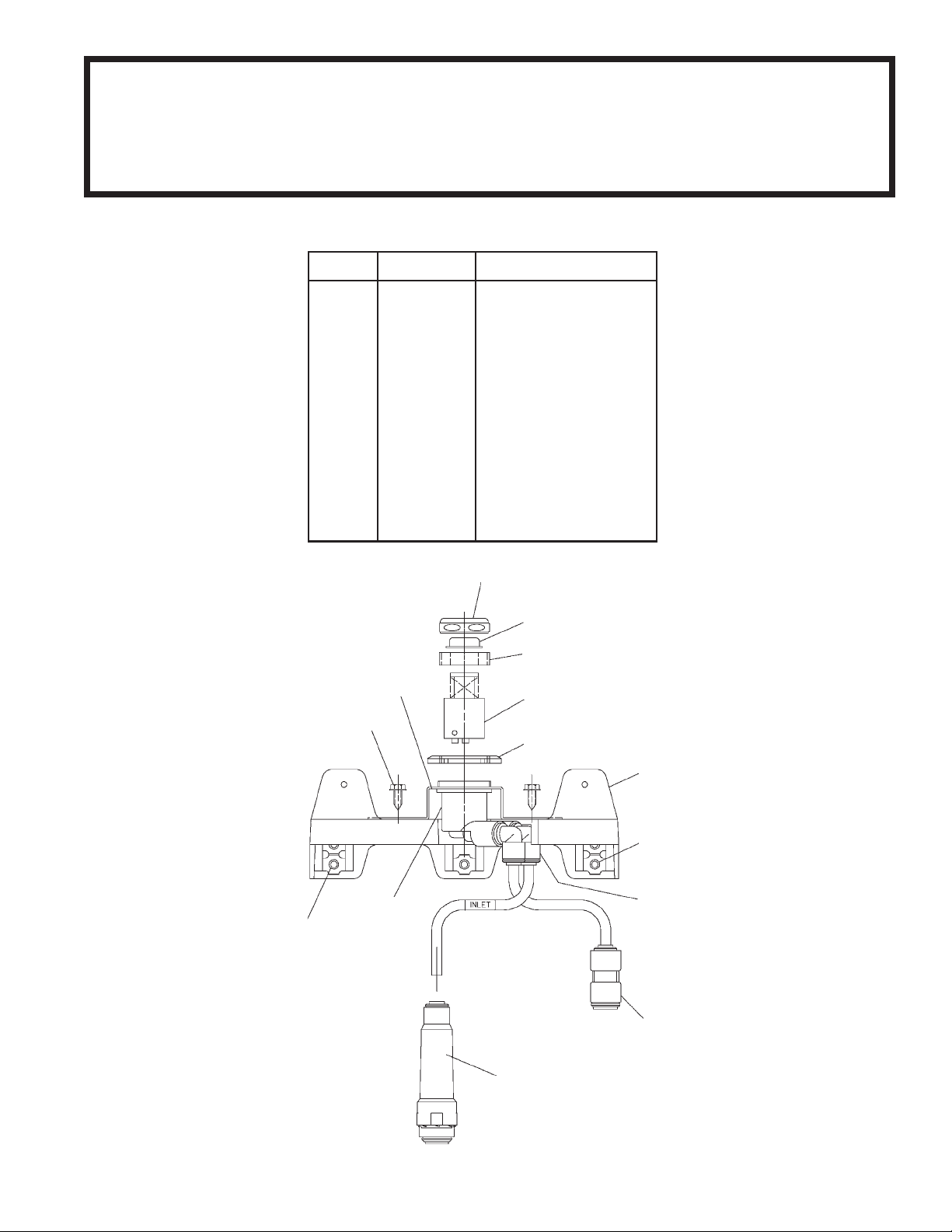
ITEMIZED PARTS LIST
ITEM NO. P ART NO.
1
2
3
4
5
6
7
8
9
10
11
12
13
NS
NS
NS
NS
40116C
40048C
15005C
61314C
40045C
51576C
401475143730
70817C
70745C
55996C
50986C
70002C
23004C
51544C
100322740560
111516043890
60291C
DESCRIPTION
Nut - Cover
Button
Nut-Retaining
Regulator
Nut - Hex
Bracket - Valve and Push Bar
Clip - Speed Strip
Elbow - 1/4" to 1/4"
Union - 3/8" to 1/4"
Strainer
Holder - Regulator
Screw - #10 x .50 HHSM
Bracket - Regulator Mtg.
Bubbler
Gasket - Black
Pin - Cotter 1/8" x 3"
Screen - SS
1
2
3
13
4
12
5
6
7
11
8
7
10
9
97218C (Rev. B - 12/07)PAGE 1
COOLER
WASTE
LINE
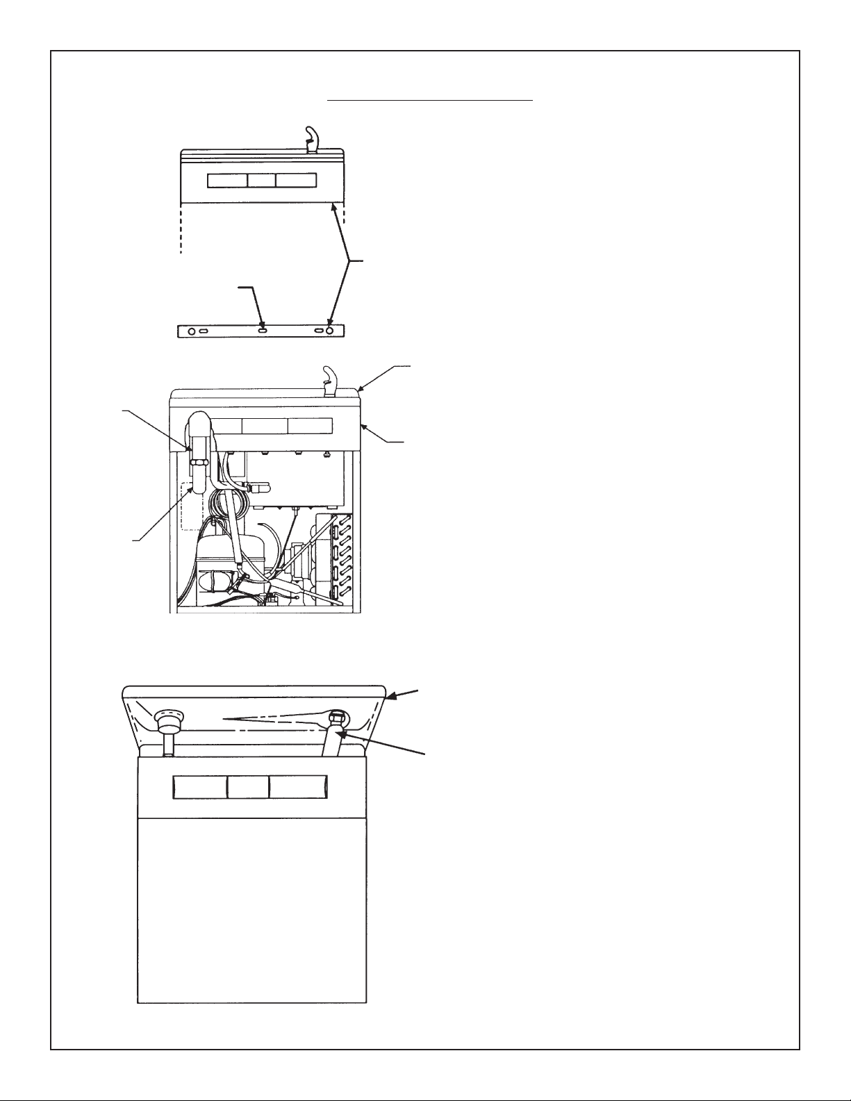
BUMPER SCREWS
Removal of Existing V alve
Remove two (2) bumper screws and two (2)
screws mounting front panel at bottom using a
5/16" and 1/4" socket or nut driver or a regular
slotted screwdriver. Loosen the (2) screws holding the front panel at the top. Remove the front
panel and set aside
FRONT P ANEL
SCREWS
RECEPTOR
SMALL
SIDE
PANELS
Loosen (2) screws on upper front panel using a
5/16" socket or nut driver. Remove upper front
panel. Unplug the water cooler from electrical
outlet. Shut off water supply.
TRAP
RECEPTOR
FLEX
COPPER
TUBE
For additional access to water valve connections.
Remove the eight (8) receptor mounting screws,
disconnect the waste line from P-trap and unscrew
the projector. Lift the receptor . NOTE: Extreme care
must be taken not to kink the flexible copper line
which supplies the projector.
97218C (Rev. B - 12/07) PAGE 2
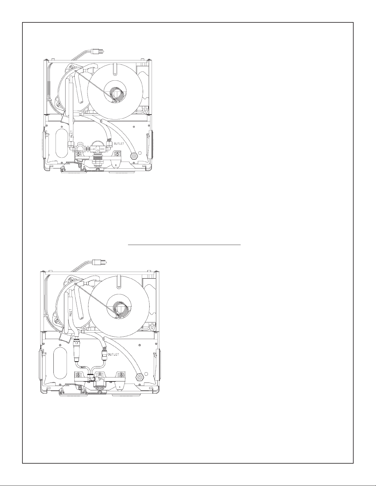
Top view of cooler
w/basin removed
Remove (5) screws holding the black plastic regulator bracket
using a 5/16" socket or nut driver.
Disconnect water inlet and outlet lines from existing water valve.
Remove regulator with bracket from the water cooler. Remove
cotter pins from bracket and remove front push bar.
If the water lines on the unit were connected to the valve with black
compression fittings:
-Remove and discard the "o"-ring and black plastic spacer
-DO NOT ATTEMPT to remove the grab ring and connection nut.
Attempting to remove the grab ring can damage, nick or scratch,
the sealing area on the tube end.
If the water lines on the unit were connected to the valve with brass
flare fittings:
-Cut the tubing as close to the flare as possible with a tube
cutter. NOTE: Only use a tube cutter to cut the tubing so the end
is square. Other tools, for example a hacksaw, could leave an
excessive burr.
-Discard the cutoff end and flare nut.
-De-burr the tube ends before assembling to the new valve
assembly.
Top view of cooler
w/basin removed
Installation Of New Valve Assembly
Connect water inlet line, from building supply to
strainer on replacement valve assembly.
Connect chiller line to super speed fitting.
97218C (Rev. B - 12/07)PAGE 3
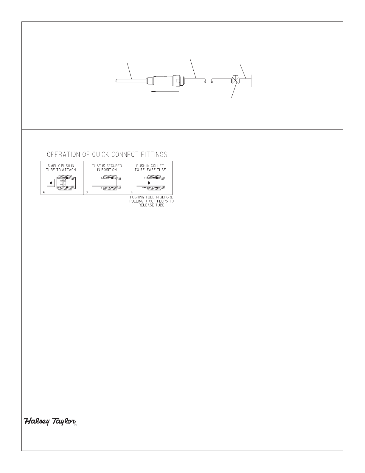
1/4" O.D. TUBE
WATER INLET
TO COOLER
3/8" O.D. UNPLATED
COPPER TUBE CONNECT
COLD WA TER SUPPLY
BUILDING WATER INLET
NOTE: WA TER FLOW
DIRECTION
SERVICE STOP
(NOT FURNISHED)
1. Push tubing into fitting until it reaches positive
stop (approximately 3/4 inches). DO NOT SOLDER
TUBES INSERTED INTO THE STRAINER AS
DAMAGE TO THE O-RINGS MA Y RESUL T .
2. To remove tubing from fitting, relieve water
pressure, push in on gray collar while pulling
out on tubing.
Turn on water supply and check for leaks. Install new projector and reposition receptor and drain tube to "P"-trap.
Adjust water flow. Flow is adjusted by removing cover and button on valve bracket, a clockwise adjustment to
screwdriver slot increases the stream height. Reassemble cover and button. NOTE: Flow must be adjusted before
push bar is installed. Install push bar on to new valve bracket. Add speed clip strip to valve bracket assembly,
(row of 4 - (1) each side). Install valve bracket into unit. Reattach receptor and reconnect wate tube to "P"-trap.
Connect power cord to electrical outlet. Reassemble panels and kickplate to unit.
2222 CAMDEN COURT
OAK BROOK, IL 60523
630.574.3500
PRINTED IN U.S.A.
FOR PAR TS, CONT ACT YOUR LOCAL DISTRIBUT OR OR CALL 1.800.323.0620
97218C (Rev. B - 12/07) PAGE 4
 Loading...