

Halo PureNight User Manual
User Guide
©2005 Halo Innovations, Inc.

ii / Safety Information
Safety Information
Please read all instructions before assembling your PureNight™ air
filtration system. Always follow the safety messages provided in this
guide.
This is the safety alert symbol. This symbol alerts you to
potential hazards during assembly, use, and maintenance
!
of your system. A safety message always follows an alert
symbol and includes the words Caution or Note.
Message indications are described below.
! Caution
A caution message indicates that people could possibly be
endangered and/or slightly hurt.
! Note
A note message indicates that a situation is possibly dangerous
or that system components might be damaged.
Please save these instructions and your
original purchase receipt.
HALO® PureNight™ Pure Air Sleep System

iii
Table of Contents
Parts List ......................................................................... 1
Assembly ......................................................................... 3
System Operation.......................................................... 13
Maintenance.................................................................. 17
Troubleshooting ............................................................ 20
Frequently Asked Questions ......................................... 21
Replacement Parts ........................................................ 23
Warranty Information................................................... 24
PureNight™ Air Filtration System Warranty Card ......... 27
HALO® PureNight™ Pure Air Sleep System

iv
HALO® PureNight™ Pure Air Sleep System
Parts List / 1
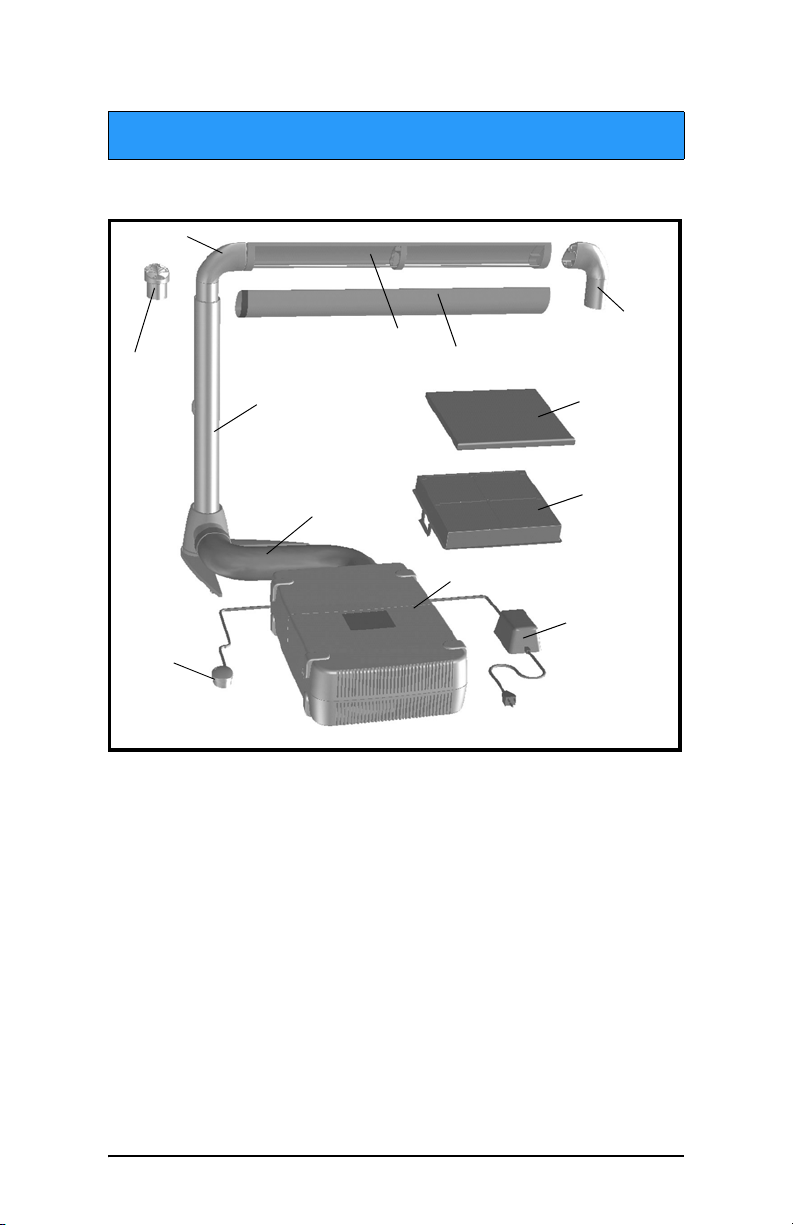
Parts List
The PureNight™ air filtration system includes the following parts.
11
11
9
8
10
7
4
3
1
1. Foot switch and cable
2. Power supply and cord
3. Central filtration unit
4. Acoustic tube with fabric cover
5. High-efficiency particulate air (HEPA) filter
6. Pre-filter
7. Tower
8. Tower cap
™
9. PureNight
10. PureNight
arm
™
sleeve
11. Elbows (left and right)
6
5
2
HALO® PureNight™ Pure Air Sleep System

2 / Parts List
System Parts and Functions
Table 1 describes the functions of the parts.
Table 1: System Parts and Functions
Part Function
1. Foot switch and cable
2. Power supply and cord
3. Central filtration unit
4. Acoustic tube with fabric cover
Allows fan-speed adjustment and
alerts you of a filter change
Provides low-voltage power to the
central filtration unit; UL listed
Houses the HEPA filter,
pre-filter, and fan
Connects the central filtration unit to
the tower; provides flexible positioning
and reduces noise
5. HEPA filter Purifies the air
6. Pre-filter refill
Includes 4 replacement pre-filters
pack
7. Tower Directs purified air upwards; provides
a stable base and varied height adjustment to fit your sleeping environment
8. Tower cap Slides onto the top of the tower for
daytime use as a decorative, protective
cover
9. PureNight
™
arm
Projects low-flow, purified air over the
sleeping area
10. PureNight
™
sleeve Slips onto the PureNight™ arm to dif-
fuse the purified air
11. Elbows (right and left)
Connects the tower to the PureNight
arm; choose right or left depending on
bedside set up
HALO® PureNight™ Pure Air Sleep System
™
Assembly / 3
Assembly
Follow these instructions to assemble your PureNight™ air filtration
system. Only a tape measure is required during assembly.
Set Up the Tower
1. Place the tower assembly on a level surface next to the side of
the bed on which you normally sleep.
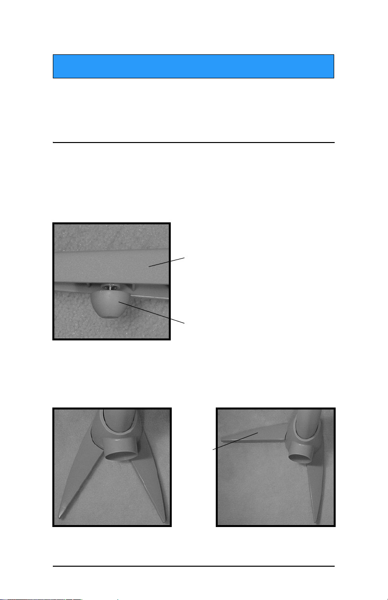
2. To vertically align the tower assembly, turn the foot pegs underneath the tower legs (Figure 1) to the right or left.
Tower leg
Foot peg
Figure 1: Foot pegs for vertical alignment
3. Slide the legs inwards or outwards to a minimum 45° angle.
A 90° angle is recommended for greater stability (Figure 2).
Slide
outward
leg under
bed
45° angle
Figure 2: 45° angle and 90° angle leg adjustments
HALO® PureNight™ Pure Air Sleep System
90° angle
recommended
for greater
stability
4 / Assembly
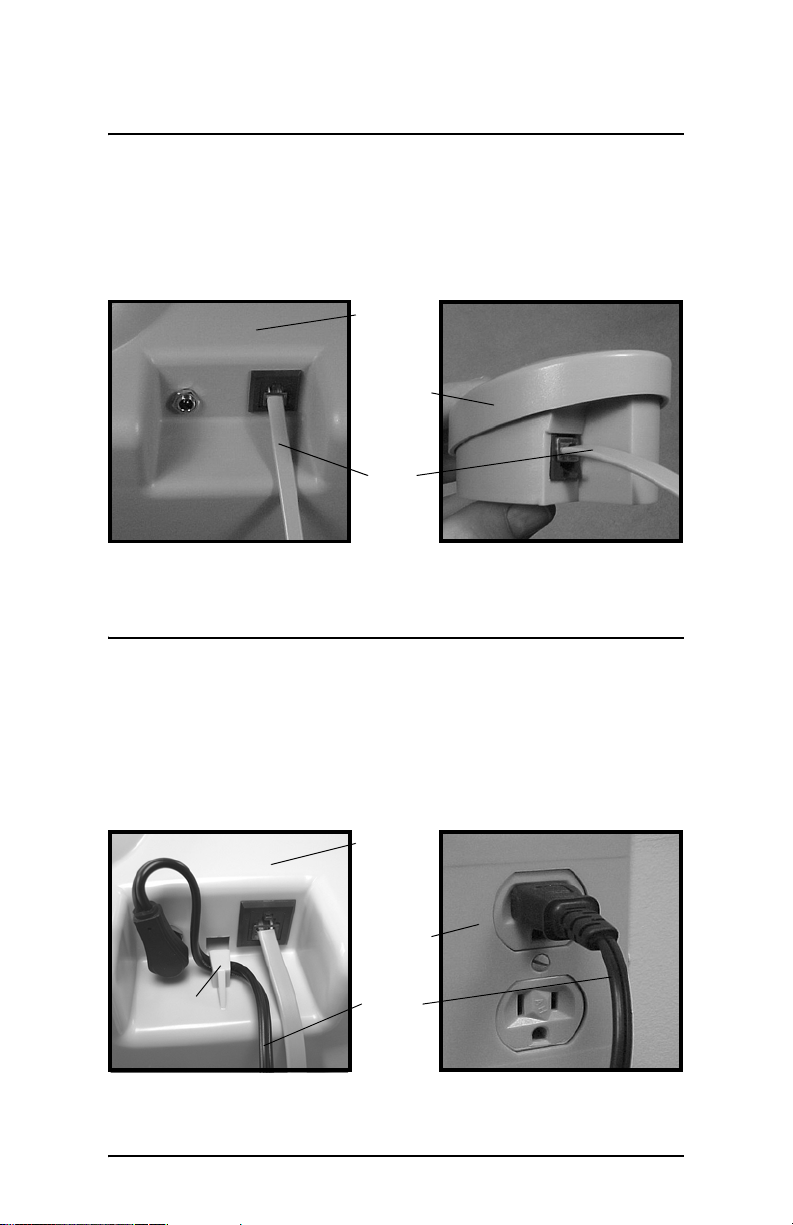
Connect the Foot Switch
1. Connect one end of the foot switch cable to the central filtration unit, as shown in Figure 3.
2. Connect the other end of the cable to the foot switch, also shown in Figure 3.
Central
filtration
unit
Foot
switch
Foot
switch
cable
Figure 3: Foot switch cable connections
Connect the Power Supply
1. Connect the power supply cord to the central filtration unit, as
shown in Figure 4, by looping the cord through the strain-relief
hook.
2. Plug the other end of the power supply cord into an electrical outlet, also shown in Figure 4.
Central
filtration
unit
Outlet
Strain-
relief
hook
Figure 4: Power supply cord connections
HALO® PureNight™ Pure Air Sleep System
Power
supply
cord
Assembly / 5
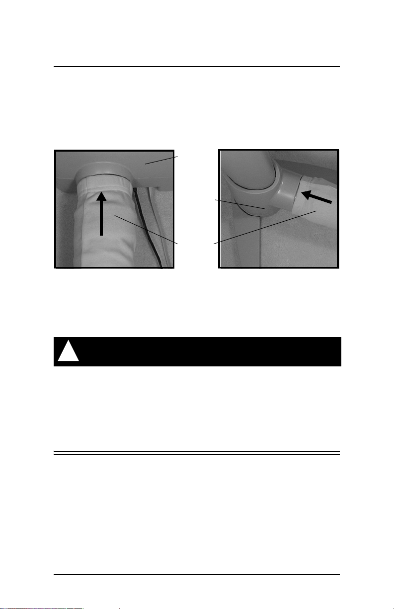
Attach the Acoustic Tube
1. Attach one end of the acoustic tube to the back of the central
filtration unit, as shown in Figure 5.
2. Attach the other end of the acoustic tube to the front of the tower base, also shown in Figure 5.
Central
filtration
unit
Tower
base
Acoustic
tube
Figure 5: Acoustic tube connections
3. Pull the fabric cover over the gaps on both ends of the acoustic tube.
! Caution
Attach the acoustic tube with the central filtration unit
turned off.
Although the central filtration unit is equipped with a finger
guard, use caution when attaching the acoustic tube to the unit.
HALO® PureNight™ Pure Air Sleep System
6 / Assembly
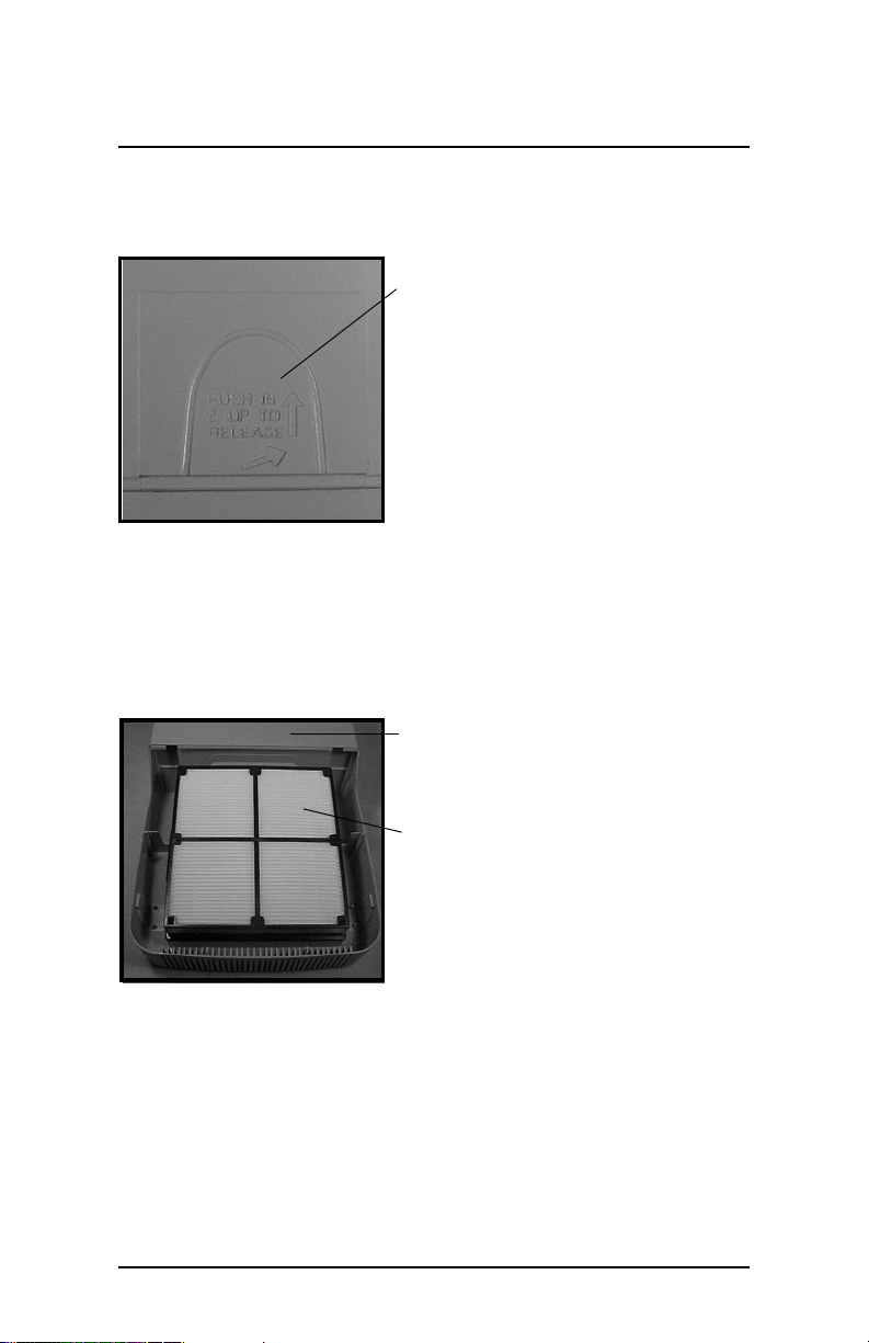
Install the HEPA Filter and Pre-Filter
1. Using both hands, simultaneously push the tabs (Figure 6) on
the side of the central filtration unit to remove the filter cover.
Push in and up to
release filter
cover
Figure 6: Filter cover tab
2. Remove the plastic packaging from the HEPA filter.
3. Snap the HEPA filter into the central filtration unit, as shown in Figure 7.
Central filtration
unit with filter
cover removed
HEPA filter with
plastic removed
Figure 7: Correct placement of HEPA filter in central filtration unit
4. Remove one of the pre-filters from the pre-filter refill pack.
5. Lay the pre-filter onto the HEPA filter.
HALO® PureNight™ Pure Air Sleep System
Assembly / 7
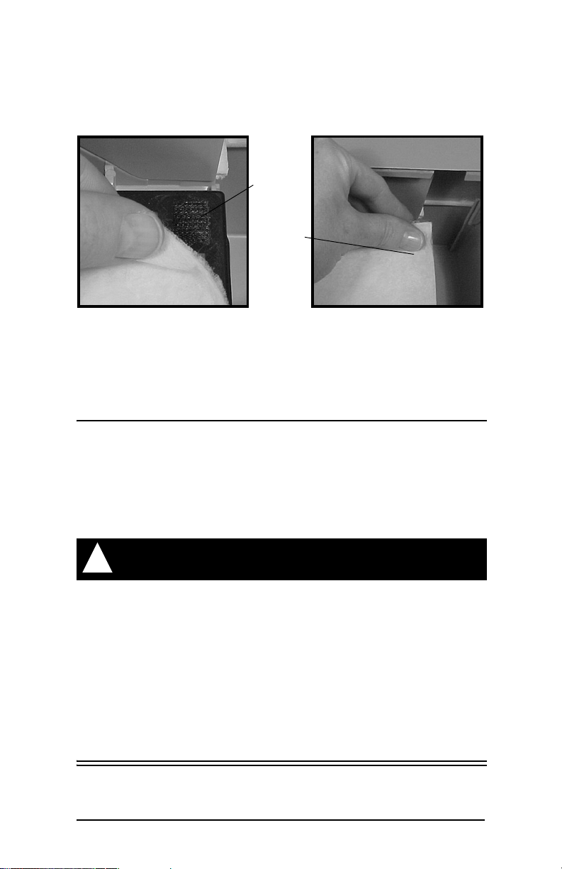
6. Gently press the pre-filter against the Velcro® tabs in each
corner and side of the HEPA filter, as shown in Figure 8.
Velcro®
tab
Press to
attach
Figure 8: Correct pre-filter placement
7. Replace the filter cover on the central filtration unit by firmly
pressing down on the corners until the cover snaps into place.
Conceal the Central Filtration Unit
1. Slide the central filtration unit—attached to the acoustic tube,
foot switch, and power supply—underneath your bed.
2. Adjust the flexible acoustic tube as necessary until all cords and
components, except the tower assembly, are beneath your bed.
! Note
To prevent restricted air flow, leave at least 6 inches of space
around the air-inlet grill on the central filtration unit.
The central filtration unit is designed to fit underneath a
standard-sized bed frame. If the unit does not fit beneath your
bed, we recommend you insert risers under each bed post. If
you are still unable to slide the unit under your bed, you may
position the unit on its side, on a level surface next to the bed.
HALO® PureNight™ Pure Air Sleep System
 Loading...