

Page 1

1
UMA1234 Rev. NC
GUI Insert
Order toll-free in the U.S. 800-959-6439
FREE technical support, Call 714-641-6607 or fax 714-641-6698
Address: Hall Research, 1163 Warner Ave. Tustin, CA 92780
Web site: www.hallresearch.com E-mail: info@hallr esearch.com
CUSTOMER
SUPPORT
INFORMATION
GUI User’s Manual
VSA-X21
HDMI Audio Extractor with 50 Watt Audio
Amplifier, HDBT Input, Line Audio Input
RS-232 Ports and IP Control
(Telnet & Internal Web GUI)
Page 2

2
User’s Manual
2
1. VSA-X21 Windows™ Software Installation
1.1. General
The VSA-X21 is controllable via free Windows® based software available from the Hall
Research website. All of the device features, and more, are accessible and controllable
from the GUI.
1.2. Software Installation Prerequisites
A PC with Windows XP® OS or later
USB port
Microsoft® .NET Framework 3.5 or later (most recent OS including Windows 8
and later include this software and no action is required). If the .NET
Framework 3.5 or later is not installed on your PC, the Microsoft™ website has
free downloads available.
1.3. Software Installation
If an earlier version of this particular software was previously installed, UNINSTALL
the program first from either the Add/Remove Programs section of the control panel
or by running the previous installation’s SETUP.EXE and selecting “remove
application”.
Install the software by executing the SETUP.EXE program from the installation
source directory
Accept the default settings, but if you want to specify a particular installation
directory other than the default, you may do so.
Once the VSA-X21 software installation has completed, either click the desktop
icon or navigate the Start Menu to
Start -> Programs -> Hall Research -> VSA-X21 Amplifier
Page 3

3
3
MODEL VSA-X21
2. Using the Software
2.1. General
For most installations the use of the software GUI is not required as most functions
can be performed using the front panel buttons on the product.
The software GUI allows the user to customize many of the VSA-X21 features to
help with installation issues and usage.
You can use the software to import/export EDID files from the device. Custom EDID
data can also be written to devices connected to the output if they support that
function.
It is possible to connect more than one VSA-X21 to the PC (using several USB ports
of the PC). The same software GUI detects all connected devices and allows control
from the same application.
2.2. USB Device Detection
The VSA-X21 software uses standard Windows® drivers, which automatically
configure the USB port after connection and do not require the installation of any
special USB drivers.
The first time you connect the VSA-X21 to the PC, you may experience a short
delay and a windows notification pop-up message may be shown.
2.2.1. The software GUI scans the VSA-X21
settings continuously in real time, all
device changes are immediately reflected
on the software GUI.
2.2.2. If no VSA-X21 device is attached to the
system, the on-screen fields are disabled
(grayed out).
2.2.3. Only one instance of the software GUI can run at
a time. Attempting to execute the application
more than once will result in a warning message.
The new device detection and driver auto installation typically only occurs
once. Thereafter, reconnected devices are detected with no delay or
message.
Page 4

4
User’s Manual
4
2.3. Tool Bar Menu
2.3.1. EXIT
Exits the application
2.3.2. RESTORE
Restore previously saved configuration files
2.3.3. SAVE
Save the current configuration file.
2.3.4. TOOLS
Factory Defaults
Restore the device to factory default settings.
The user must confirm the action.
Import EDID
Import an EDID (256-byte binary or XML file) into the unit. (If the file has an
XML extension, the file will be interpreted as containing XML data; otherwise,
the file will be interpreted as containing BINARY data). Uploading invalid files
will result in EDID corruption.
Export EDID
Save the current EDID as a 256-byte binary file
This file can be edited using third party software and reloaded using the ‘Import
EDID’ tool selection.
Firmware Update
Allows users to field upgrade the device application firmware.
Only valid firmware files can upload into the VSA-X21.
LAN Update
Allows users to field upgrade the device application LAN firmware
(WEBGUI).
Page 5

5
5
MODEL VSA-X21
2.3.5. ABOUT
Displays screen with software versions,
website link, legal disclaimer and copyright
information. The Serial # information
displayed is a time/date stamp referenced
to GMT (Greenwich Mean Time) and has
no reference to the serial number sticker on
the actual device.
2.4. Device Name
Assigns a descriptive name to be given to the VSA-X21 device that
is a maximum 8 characters long.
The user is not allowed to change the device name with multiple devices connected.
The FACTORY DEFAULT name is USBDEVHR.
2.5. Status Bar
The bottom bar of the screen shows the current USB status as follows:
“Scanning for Hardware…”
The GUI software is looking for VSA-X21 devices.
Screen controls disable until a valid VSA-X21 device attached
“Connected – XX”
Where XX is the number of VSA-X21 devices connected to the PC.
Page 6

6
User’s Manual
6
2.6. Status Group
Power
The Power
control shows the device power state as well as
being able to control the ON or OFF state. Factory default is
ON.
Video Input
No Video
Indicates the system is not receiving an INPUT video signal.
HDCP On
Indicates video received has HDCP Encryption enabled.
HDCP Off
Indicates video received has HDCP Encryption disabled.
NO MHL
Indicates the MHL status of the connected HDMI source.
Audio Input
No Audio
Indicates no audio received (DVI mode)
Multi-Channel
Indicates HDMI audio received is not LPCM format.
2 Chn
Indicates HDMI audio received is LPCM format.
Video Output
+5 ON/OFF
Indicates the state of the +5 vDC signal to the HDMI
OUTPUT. When the HDMI INPUT +5 vDC is connected, the
+5 vDC OUTPUT signal is turned on and this indicator will be
green. When no +5 vDC signal is detected on the HDMI INPUT, the indicator on
the screen changes to a dark red color.
Connected or Disconnected
Indicates the state of the device connected to the VSA-X21 HDMI OUTPUT.
When a HPD signal is detected, the button will be green and the word Connected
will be shown next to it.
When no display is detected (or the display is not sending an HPD signal), then the
indicator on the screen changes to a dark red color and the word Disconnected
will be shown next to it.
Page 7

7
7
MODEL VSA-X21
2.7. Audio Tab
Control
The current device temperature and fan
percentage are displayed.
The Fan turns on @ 120 degF at 55%
fan percentage. The fan reaches 100%
at 160 degF.
Audio Mix
The Line
control shows the device
LINE Audio state as well as being
able to control the ON or OFF state. Factory default is ON.
When ON, the 3.5mm LINE IN audio is mixed and output on the amplifiers
speakers and 3.5mm LINE OUT connectors.
When OFF, the 3.5mm LINE IN audio is not mixed and not output.
The HDMI control shows the device HDMI Audio state as well as being able to
control the ON or OFF state. Factory default is ON.
When ON, the HDMI IN audio is mixed and output on the amplifiers
speakers and 3.5mm LINE OUT connectors.
When OFF, the HDMI IN audio is not mixed and not output.
The HDMI Mode control shows the device HDMI Mode state as well as being
able to control the HDMI or ARC state. Factory default is HDMI.
When OFF, the HDMI IN audio is mixed and output on the amplifiers
speakers and 3.5mm LINE OUT connectors.
When ON, the HDMI OUT ARC audio is mixed and output on the amplifiers
speakers and 3.5mm LINE OUT connectors.
The Stereo/Mono
control shows the device Stereo/Mono audio state as well
as being able to control the Stereo or Mono audio output state.
Output Volume
The Up
control increases the volume by 1% for each click.
The Down control decreases the volume by 1% for each click.
The Mute control shows the device audio MUTE state as well as being able to
control the MUTE state. Factory default is OFF.
When ON, the speaker and 3.5mm LINE OUT audio is muted.
When OFF, the speaker and 3.5mm LINE OUT audio is NOT muted.
The volume Slider control adjusts volume as the user changes the control.
Factory default is 0%.
Line Input Gain
The volume Slider
control adjusts the gain of the 3.5mm LINE IN audio as the
user changes the control. Factory default is 70%.
Page 8

8
User’s Manual
8
Active Input
The Active Input control shows the device current video input
as well as being able to control the selected input.
‘Local’ is the Local HDMI IN on the rear panel.
‘HDBT #1’, ‘#2’ and ‘#3’ refer to the video source connected to
the HDBT IN connector.
When the UHBX-SW3-WP/S is used, each HDBT input refers
to the corresponding input on the UHBX-SW3-WP/S.
Input Priority
The Input Priority control shows the device current setting
as well as being able to control which video input (HDMI or
HDBT) has priority or whether the ‘Last Plugged’ video
source is to be selected.
MANUAL CONTROL
o The video inputs have no priority.
o The user can manually select which video input is active
HDBT over Local
o The HDBT video input has priority over the Local video input.
o The Active Input controls disable in this mode.
o When a video source is detected on the HDBT input, the device will
automatically switch to that video input.
o If the video source is removed, the device will automatically switch
back to the Local HDMI input if that input has an active video source.
Local over HDBT
o The Local video input has priority over the HDBT video input.
o The Active Input controls disable in this mode.
o When a video source is detected on the Local input, the device will
automatically switch to that video input.
o If the video source is removed, the device will automatically switch
back to the HDBT input if that input has an active video source.
Last Plugged
o The device switches to the video input that has an active source
attached last.
Page 9

9
9
MODEL VSA-X21
Rear TB Functions
The Rear TB Functions
control shows the device setup
for the terminal strip functionality, where different
controls or sensors may be connected.
Factory default is ENCODER.
Encoder - Volume
o A compatible encoder connected on the
rear terminal strip controls the device volume. (Compatible with Model
UI-KNOB-DP)
Page Sensor - Mute
o A compatible page sensor connected on the rear terminal strip
controls the MUTE function. (Compatible with Model VSA-PGSNS)
o Whenever a signal is received of sufficient amplitude, the 3.5mm LINE
IN and HDMI/ARC audio will be muted.
o When the signal received is below the paging threshold, the 3.5mm
LINE IN and HDMI/ARC audio will NOT be muted.
Contact - Mute
o When the CW and GND terminals are closed, the audio output will be
muted.
o When the CW and GND terminals are open, the audio output will NOT
be muted.
Page 10

10
User’s Manual
10
Auto Detection Method
The Auto Detection Method
control field shows the device
current Auto Detection Method state as well as being able to
control the Auto Detect Method state. Factory Default is
DISABLED.
Disabled
o Auto Detection is disabled
o The Off Delay control is disabled in this mode.
o The AUTO button in the WEBGUI is hidden in this mode.
+5V
o When +5 vDC is present on the currently selected input (Local or
HDBT), the ON string associated with the AUTO function will be
processed.
o When the +5 vDC is no longer present, the OFF string associated with
AUTO will be processed after the programmed Off Delay
time has
elapsed.
o The Off Delay control is enabled in this mode.
o The AUTO button in the WEBGUI is visible in this mode.
Video
o The video source must actually send video in order to be detected.
o When video is received on the currently selected Input (Local or
HDBT), the ON string associated with the AUTO function will be
processed.
o When the video is no longer active, the RS-232 OFF string OFF string
associated with AUTO will be processed after the programmed Off
Delay time has elapsed.
o The Off Delay control is enabled in this mode.
o The AUTO button in the WEBGUI is visible in this mode.
Contact
o When terminals CCW and GND are closed, the ON string associated
with AUTO will be processed.
o When CCW and GND are open, the OFF string associated with AUTO
will be processed.
o The Off Delay control is disabled in this mode.
o The AUTO button in the WEBGUI is visible in this mode.
Page 11

11
11
MODEL VSA-X21
Auto Detection
The Auto Detection Active/Inactive button shows the device current setting as well
as being able to control whether an active source will be detected or not.
Auto Detection Off
o No action is taken.
o Factory default is OFF.
Auto – Triggered or Waiting
o When the Auto Detection Method
control is NOT disabled, the device
will process the RS232 ON and OFF strings associated with the
AUTO function whenever a specified event (+5 or Video) occurs.
o Waiting signifies that the device is still waiting
for the specified event to occur.
o Triggered signifies that the device has detected
the specified event.
Off Delay (min)
The Off Delay (min)
control field shows the device current off delay
value as well as being able to set that value. Factory Default is 3
minutes.
The control is disabled if the Auto Detection Method
is set to Disabled or
Contact.
When set to 0 minutes and ‘Auto Detection Method
’ is set for ‘+5’ or ‘Video’
the RS232 OFF string associated with the AUTO Function will be processed
immediately.
When set to any value between 1 and 240 minutes, the RS232 OFF string
associated with the AUTO Function will be processed after the programmed
delay has elapsed.
Page 12
12
User’s Manual
12
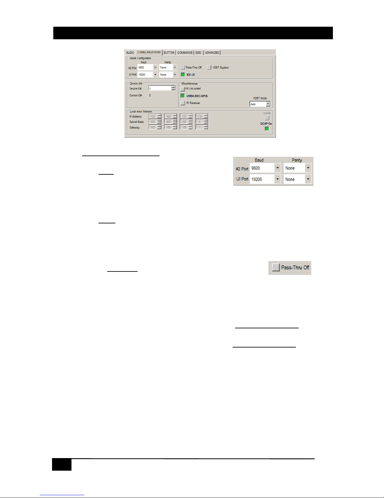
2.8. Communications Tab
Serial Configuration
Baud
The Baud
controls show the device baud rate
setting for the available serial ports.
Factory default is 9600 for Serial Port #2
Factory default is 19200 for the X21-UI serial port (when installed)
Parity
The Parity
controls show the device parity setting for the available serial ports.
Factory default is NONE for Serial Port #2
Factory default is NONE for the X21-UI serial port (when installed)
Pass-Thru
The Pass-Thru
control shows the device RS232 PassThru state as well as being able to control the ON or
OFF state. Factory default is OFF.
The available serial ports can be either the Serial Port #1 on rear of device, the
X21-UI serial port (when installed) or the HDBT TX serial port (when available).
When ON, RS232 characters received from any of the serial ports
are
‘Passed thru’ to Serial port #2 unchanged.
When OFF, RS232 characters received on any of the serial ports
are NOT
‘Passed thru’ to Serial port #2.
Page 13

13
13
MODEL VSA-X21
HDBT Bypass
The HDBT Bypass
control shows the device current
HDBT Bypass state as well as being able to control the
ON or OFF state.
Factory default is OFF.
When enabled, any characters received on the HDBT IN will be bypassed
directly to Serial port #2.
NOTE:
The ‘Baud’ and ‘Parity’ controls do not apply when this control is enabled.
The baud rate used is whatever the HDBT TX device used.
The HDBT RS232 stream will NOT be able to control the VSA-X21 in this mode.
X21-UI
The X21-UI
control setting shows the device current setting
as well as being able to control the ON and OFF states.
Factory default is ON
When OFF, no special processing is done.
When ON, the device will send to and receive commands from the installed
X21-UI for control.
Device Info
Device ID#
The Device ID#
control shows the device ID#.
Factory default is 0.
Current ID #
The Current ID#
control shows the device ID#. Factory default is 0.
Page 14

14
User’s Manual
14
Miscellaneous
FP Unlocked/Locked
The FP Unlocked/Locked
control shows the device front
panel lock status. Factory default is Unlocked.
When UNLOCKED, the device front panel buttons are active.
When LOCKED, the device front panel buttons are NOT active. RS232,
webpage and telnet commands are always active even when the FP is in
the LOCKED state.
UHBX-SW3-WP/S
The UHBX-SW3-WP/S
control setting shows the device
current setting as well as being able to control the ON and
OFF states.
Factory default is ON
When OFF, no special processing of the HDBT RS232 is done.
When ON, the device will send and receive RS232 commands to/from the
installed UHBX-SW3-WP/S for control.
IR Sender/Receiver
The IR Sender/Receiver
control shows the device current
setting as well as being able to control the IR Receiver or IR
Sender States.
Factory default is IR Receiver
When set to IR Receiver, ANY IR Signals sensed are sent to the HDBT TX
for IR output. (compatible with Model CIR-DET-P2)
When set to IR Sender, ANY IR Signals received from the HDBT TX device
OR the UHBX-SW3-WP/S (if installed) OR the X21-UI (if installed) is
transmitted from the 3.5mm IR output on the device rear panel. (Compatible
with Model CIR-EMT or CIR-KIT-EMT2)
Page 15

15
15
MODEL VSA-X21
Local Area Network
IP Address
The IP Address
control shows the
device IP address.
Factory default is DHCP so the end
users compatible DHCP router determines this address.
Subnet Mask
The Subnet Mask
control shows the device subnet mask.
Factory default is DHCP so the end users compatible DHCP router determines this
subnet mask.
Gateway Address
The Gateway Address
control shows the device Gateway address.
Factory default is DHCP so the end users compatible DHCP router determines this
address.
DHCP
The DHCP
control shows the device DHCP status.
Factory default is ON.
When OFF, the IP address, Subnet Mask and Gateway address are
determined by the settings in the other fields (after the UPDATE button is
clicked).
When ON, the IP address, Subnet Mask and Gateway address are
determined by the end users compatible DHCP router.
UPDATE
The UPDATE
control is enabled only when DHCP is OFF and a setting
has been changed.
Click this control after setting the IP address, Subnet Mask and Gateway address
to the desired STATIC settings.
Page 16

16
User’s Manual
16
2.9. Buttons Tab
These controls configure the eight
programmable buttons that appear in the
WEBGUI and on the X21-UI
Name
The name for the button that will appear
on the WEBGUI button.
Function
The VSA-X21 system function associated
with the button. When pressed, buttons
will execute the assigned function.
Type
The button type can be set for
Momentary or Toggle action.
Toggle buttons have two RS-232 strings
associated with them.
Momentary buttons have one RS-232
string associated with them.
Group
The button group assigned to this button.
Multiple buttons can be assigned to the
same group #.
Only one button in the group can be
active at one time.
Enable?
Whether the button is enabled or not.
Buttons that are not enabled do not
respond and the button is removed from the WEBGUI.
Page 17

17
17
MODEL VSA-X21
2.10. Commands Tab
Command Configuration
Button Action
The Button Action
control field shows the
individual ON or OFF strings for the 8
programmable buttons.
Function
The Function
control field shows one of the following values.
Serial
o Send RS232 to Serial Port #2
Serial (UI)
o Send RS232 to the X21-UI serial port (when installed)
Serial (HDBT)
o Send RS232 to HDBT serial port (when installed)
Delay
o Time delay from 1 to 6 seconds
Command
o Send any valid command to the device
IR (UI)
o Send IR code from X21-UI (when installed)
Command (when Function is set for Serial, Serial (UI) or Serial (HDBT))
The Command
control field is where the user enters the desired RS232 string.
The RS232 values can be entered as ASCII text and/or hex byte values
formatted in a &hXX format.
Any extra spaces or other characters entered are transmitted.
Where “XX” is the desired HEX byte value.
Any character from 0 to 0xFF can be entered in this format.
Delay (sec) (when Function set for Delay)
The Delay (sec)
control field is where the user enters the desired time delay in
seconds. The limit is from 1 to 6 seconds.
Page 18

18
User’s Manual
18
INSERT
The INSERT
control appends a new command. If the
new command exceeds the maximum length allowed,
a window will be displayed. (32 characters maximum).
Each Function
uses a different number of characters
over and above any fixed characters that are required.
CLEAR
The CLEAR
control is clicked to erase the entire pre-programmed command
sequence.
UPDATE
The Update
control is clicked to save the existing programmed command.
This control is only visible when an unsaved change has been made to the
configuration.
2.11. Programming the VSA-X21
RS-232 baud rate, parity and control information for the SINK device may
be required.
o Gather the information from the manufacture of the SINK device.
Configure for optional equipment installed
o UHBX-SW3-WP/S (Communications Tab)
o UI-KNOB-DP (Communications Tab)
o VSA-PGSNS (Communications and Advanced Tabs)
o X21-UI (Communications and Button Tabs)
By default, all buttons are disabled, but have no Function or RS-232
strings assigned so they will only turn on the LED on and off on the
X21-UI and/or WEB GUI.
Learning the SINK EDID and having it stored in the VSA-X21 can reduce
EDID colorspace and audio issues.
o Set VSA-X21 to EMULATE the EDID.
o If UHBX-SW3-WP/S is also used, set its GUI EDID for ‘Pass-Thru’.
EXAMPLE CONFIGURATION
To send the RS232 string “PWR ON” followed by a Carriage Return character out Serial Port #2 and then wait
5 seconds.
Select the desired Button Action for this command. (Ie… Which button should be used to send this
command?)
Select Serial from the Function control.
Enter the characters PWR ON&h0D into the ‘COMMAND’ field and click ‘INSERT’.
Select Delay from the Function control.
Set the Delay (sec) to 5 and click ‘INSERT’.
Click ‘UPDATE’ to save the command.
Page 19

19
19
MODEL VSA-X21
2.12. EDID Tab
VIDEO EDID
Clicking these controls selects to either PASS-THRU or
EMULATE the EDID.
PASS-THRU uses the SINK EDID while EMULATE uses the
internal EDID saved in the VSA-X21.
PASS-THRU is the FACTORY DEFAULT setting.
Learn EDID
Clicking this control will extract the EDID from device
connected to the output connector and save it in the unit.
The user must confirm the action.
EDID Data Display
The data shown in the EDID table is continually
scanned to ensure that the checksums for each
block is valid.
When wrong checksums are detected, the
invalid checksum byte is highlighted in RED.
If an action is performed that affects the EDID such as initiating a "learn" process,
The checksum field might momentarily flash ‘RED’ during the this process, but
should go back to normal once the entire table is updated.
NOTE
You cannot “LEARN” an EDID that has an invalid checksum. If you try to learn an EDID that has a
checksum error, the HDMI and MUTE Button LEDs on the unit will alternately flash 5 times to
indicate the error.
No other checks are performed on the EDID to determine that it is valid per the EDID standard.
However, the GUI software can import and upload to the VSA-X21, EDID’s that contain invalid
checksum for testing purposes.
Page 20

20
User’s Manual
20
2.13. Advanced Tab
Ducking & AutoMute
AutoMute Threshold
The AutoMute Threshold
control shows
the device current setting and allows
the setting to be adjusted between 0
and 100%. Factory default is 0%.
(Technically, this is ‘OFF’ since the
audio level cannot go below 0%)
When the 3.5mm LINE IN audio level is below the AutoMute Threshold value, the
LINE IN audio will be muted after the AutoMute Delay time has elapsed.
The LINE IN audio will be immediately un-muted with audio level is above the
AutoMute Threshold value.
Ducking Threshold
The Ducking Threshold
control shows the device current setting and allows the
setting to be adjusted between 0 and 100%. Factory default is 100%. (Technically,
this is ‘OFF’ since 100% cannot be exceeded)
If the 3.5mm LINE IN audio level exceeds this amount, the HDMI/ARC volume will
be reduced by the given ‘Ratio’.
Ratio
The Ratio
control shows the device Ducking Threshold ratio. This is the percentage
the HDMI/ARC volume is reduced when the Ducking Threshold is exceeded.
Factory Default is 50% (ie… cut the HDMI volume in half)
PageSense
Threshold
The Threshold
control shows the device Paging Sensor voltage threshold. Factory
default is 100%. (Technically, this is ‘OFF’ since 100% cannot be exceeded)
If the Paging Sensor input voltage exceeds this amount, the audio output will be
muted.
When the input voltage goes below this amount, the audio output will be un-muted.
Overcurrent
Threshold
The Threshold
control shows the device Overcurrent voltage threshold. Factory
default is ~30%.
Example
When the Ducking Threshold is exceeded, whatever volume level the HDMI/ARC is
currently set for will be reduced by the ‘Ratio’.
If the volume level is currently set to 75% and the ‘Ratio’ is set for 50%, when the Ducking
is in effect, the output volume level will be set for 75% * 50% = 37.5%.
Page 21

21
21
MODEL VSA-X21
Page 22

22
User’s Manual
22
Page 23

Page 24

© Copyright 2016 Hall Research, Inc.
All rights reserved.
Order toll-free in the U.S. 800-959-6439
FREE technical support, Call 714-641-6607 or fax 714-641-6698
Mail order: Hall Research, 1163 Warner Ave. Tustin, CA 92780
Web site: www.hallresearch.com E-mail: info@hallr esearch.com
CUSTOMER
SUPPORT
INFORMATION
 Loading...