

Page 1
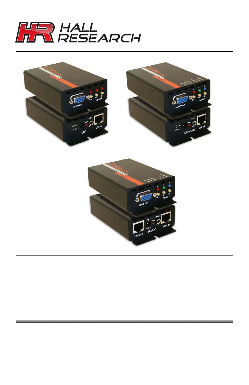
User’s Manual
URA
URA-XT
URA-SKU
URA, URA-SKU, & URA-XT
PC Video & Audio on Twisted-Pair Receivers
with Cable Length Compensation
Skew Correction and Daisy-Chain Output
CUSTOMER
SUPPORT
INFORMATION
Order toll-free in the U.S. 800-959-6439
FREE technical support, Call 714-641-6607 or fax 714-641-6698
Address: Hall Research, 1163 Warner Ave. Tustin, CA 92780
Web site: www.hallresearch.com E-mail: [email protected]
UMA1168 Rev. NC
Page 2

Page 3
PC (VGA) & HD (YPbPr) AV over Twisted-Pair Receivers
TRADEMARKS USED IN THIS MANUAL
Hall Research and its logo
Any other trademarks mentioned in this manual are acknowledged as
the property of the trademark owners.
are trademarks of Hall Research.
FEDERAL COMMUNICATIONS COMMISSION
RADIO FREQUENCY INTERFERENCE STATEMENT
This equipment generates, uses, and can radiate radio frequency
energy and if not installed and used in strict accordance with the
manufacturer’s instructions, may cause interference to radio
communication. This equipment is designed to comply with the limits
for a Class A computing device in accordance with the specifications
in Subpart B of Part 15 of FCC rules, which are intended to provide
reasonable protection against such interference when the equipment
is operated in a commercial environment. Operation of this
equipment in a residential area is likely to cause interference, in
which case the user at their own expense will be required to take
whatever measures may be necessary to correct the interference.
Changes or modifications not expressly approved by the party
responsible for compliance could void the user’s authority to operate
the equipment.
1
Page 4
Model URA, URA-SKU, & URA-XT
Contents
1. Introduction.................................................................3
1.1 General ...................................................................... 3
1.2 Features..................................................................... 4
2. Installation...................................................................4
2.1 Package Contents...................................................... 4
2.2 Connection to Compatible Senders ........................... 5
2.3 Cable Requirements .................................................. 6
2.4 Daisy-Chain Limitations ............................................. 6
2.5 Connection Block Diagram for URA & URA-SKU ...... 7
2.6 Connection Block Diagram for URA-XT ..................... 7
3. Configuration & Operation.........................................8
3.1 Why Cable Compensation? ....................................... 8
3.2 Compensation Adjustment Procedure ....................... 8
3.3 Advanced Adjustment (CATx AWG) .......................... 9
3.4 Why Skew Adjustment? ........................................... 10
3.5 Skew Adjustment Procedure.................................... 11
3.6 Signal Adjustment for the Daisy Chain..................... 12
4. Troubleshooting........................................................13
4.1 Contacting Hall Research ........................................ 13
4.2 Shipping and Packaging .......................................... 13
4.3 Problem Solving FAQ .............................................. 14
5. Specifications ...........................................................15
2
Page 5
PC (VGA) & HD (YPbPr) AV over Twisted-Pair Receivers
1. Introduction
1.1 General
This User’s Manual applies to Hall Research Models URA, URASKU, and URA-XT.
These models are video and audio over Category 5/5e/6 receivers. In
a typical application, they are located at a distance from the video
source and are connected to a compatible sender unit that converts
the audio and video source signal for transmission on twisted pair
cable.
Below is a list of capabilities & features of each receiver model:
Equalization
URA
URA-SKU
URA-XT
to 1000 ft
RGB Skew
Correction
Chain
Output
Cable Requirements
Low-Skew UTP Cable
Any UTP or STP Cable
Any UTP or STP Cable
Table 1 – Model Number Differences
Low-skew UTP cables (such as Hall Research’s Zero-skew™ Cat5
cables) are recommended with the Model URA particularly if cable
lengths are 200 feet or longer. The Models URA-SKU and URA-XT
do not have any special cable requirements since they are capable of
correcting the RGB color skew that is induced in typical Cat6 cables.
The Model URA-XT allows downstream receiver units to daisy chain
connections using UTP cables. This eliminates the need for running
separate cables from every receiver back to the sender (in star or
home-run fashion) – a very useful feature when several receivers are
located in a line going away from the sender.
Depending on the application, the URA-XT’s downstream RJ45 port
can be connected to another receiver (URA-XT, URA-SKU, or URA).
The constructed daisy chain may have:
• Up to 3750 feet maximum cable from source to last URA
• A maximum of 5 URA devices in any chain
• 750 feet maximum distance between units in a chain
3
Page 6
Model URA, URA-SKU, & URA-XT
1.2 Features
• Receives audio and video on a single CATx cable
• Adjustable cable length compensation to 1000 ft
• The URA–SKU and URA–XT units have RGB skew
correction
• Digitally controlled adjustment eliminates tweaking pots
• Supports resolutions up to 1920x1200 at any refresh rate
• Compact & rugged metal enclosure with mounting holes
• Easily expandable by daisy-chaining receivers (URA-XT)
• No software required for setup and use
2. Installation
2.1 Package Contents
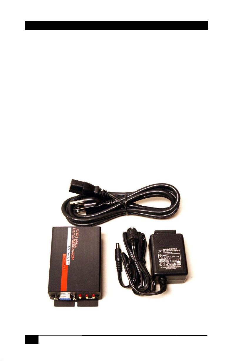
Your package should contain the URA receiver unit, a Universal
power supply (5 VDC @ 2A), an IEC320 Power Cord, and a User’s
Manual.
Figure 1 – Package Contents
4
Page 7
PC (VGA) & HD (YPbPr) AV over Twisted-Pair Receivers
2.2 Connection to Compatible Senders
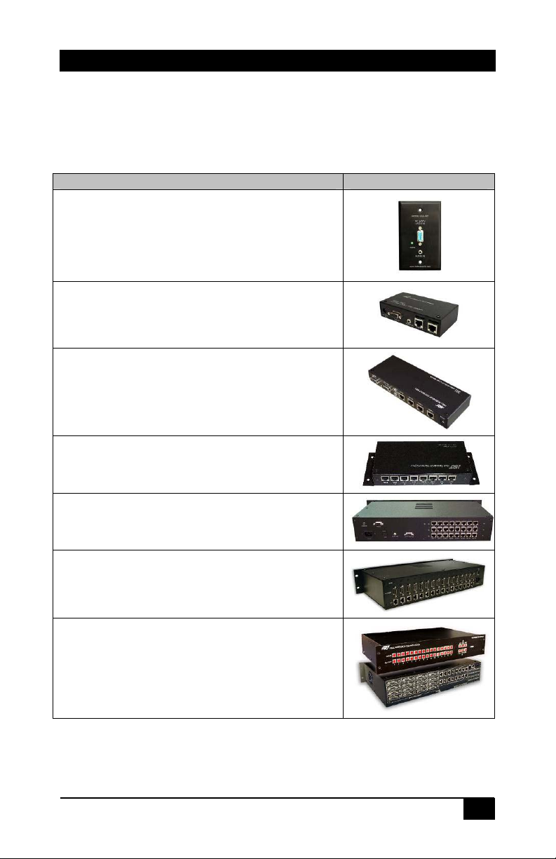
The URA, URA-SKU and URA-XT units accept a UTP cable
connection from any of Hall Research’s compatible UVA Sender
product line. Some compatible senders are listed below:
PART NUMBER
UVA-WP
VGA+Audio sender on a single-gang Wallplate.
Sends audio & VGA on standard RJ45 connector
on UTP cable. Includes a power supply. May be
powered from the VGA input connector per VESA
power specifications. EDID/DDC compliant
UVA-2
VGA+Audio 2-channel video splitter UTP sender
with local AV outputs. EDID/DDC compliant
UVA-4
VGA+Audio 4-channel video splitter UTP sender
with local AV outputs. EDID/DDC compliant
UVA-8
VGA+Audio 8-channel video splitter UTP sender
with local AV outputs. EDID/DDC compliant
UVA-24
VGA+Audio 24-channel video splitter UTP sender
with local AV outputs. EDID/DDC compliant
UVA-16X
16 independent VGA or component video &
Audio over UTP sender in a single 2 RU
enclosure.
Genesis 8x8 and 16x16 Matrix with -JA
output option
Up to 16 RJ45 outputs with video and audio that
can be switched to any of up to 16 AV inputs.
Housed a single 2 RU enclosure
Table 2 – Compatible Senders
(Always check the website for other models)
5
Page 8
Model URA, URA-SKU, & URA-XT
Connect the UTP cable from any of the compatible UVA
senders to the “UTP IN” connector.
Connect the HD15 - “PC/HDTV OUT” connector to the
display device. For YPbPr video sources, use a 3-RCA to
HD15 cable (Hall Research P/N CHD15-RGB).
Connect the 3.5mm - “AUDIO OUT” connector to the
speakers or other sound equipment.
Connect the included power supply to the 2.1mm – center
positive +5 VDC power input connector on the unit. Never
use any other supply as this may damage the device.
2.3 Cable Requirements
All units can be used with Cat5/5e/6 or Zero-Skew™ UTP or STP
(unshielded or shielded twisted pair) cables.
All units provide high-frequency compensation (to account for the
losses in the CATx cable). The URA-SKU and URA-XT units also
provide RGB skew correction.
Low-skew UTP cables (such as Hall Research’s Zero-skew™ Cat5
cables available in both PVC and Plenum) are recommended with the
Model URA particularly if cable lengths are 200 feet or longer. The
Models URA-SKU and URA-XT, do not have any special cable
requirements since they are capable of correcting the RGB color
skew that is induced in typical CATx cables.
2.4 Daisy-Chain Limitations
The Model URA-XT allows downstream receiver units to be daisy
chained using UTP cables. This eliminates the need for running
separate cables from every receiver back to the sender.
Depending on the application, the URA-XT’s downstream RJ45 port
can be connected to a URA-XT, URA-SKU, or URA. The constructed
daisy chain may have:
• Up to 3750 feet maximum cable from source to last URA
• A maximum of 5 URA devices in any chain
• 750 feet maximum distance between units in a chain
6
Page 9
PC (VGA) & HD (YPbPr) AV over Twisted-Pair Receivers
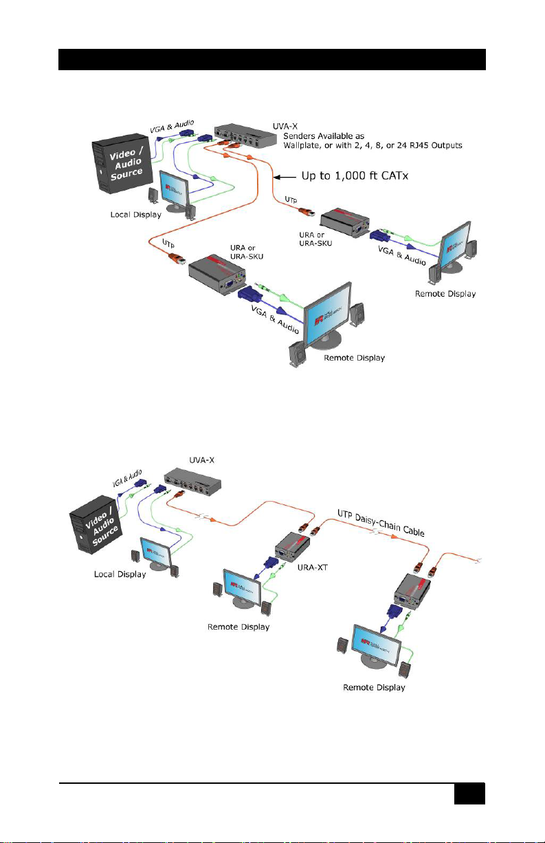
2.5 Connection Block Diagram for URA & URA-SKU
Figure 2 – URA & URA-SKU Application Diagram
2.6 Connection Block Diagram for URA-XT
Figure 3 – URA-XT Application Diagram
7
Page 10
Model URA, URA-SKU, & URA-XT
3. Configuration & Operation
3.1 Why Cable Compensation?
All cables attenuate (reduce) the high-frequency components of the
video signal that is being transmitted. The longer the cable, the more
signal loss. If not compensated for, this signal loss will result in blurry
and smeared images being displayed.
The image quality depends on the resolution and level of detail in the
image. The Hall Research URA series of receivers have one of the
most precise and complex equalization techniques in the industry and
allow full recovery of the original signal’s bandwidth.
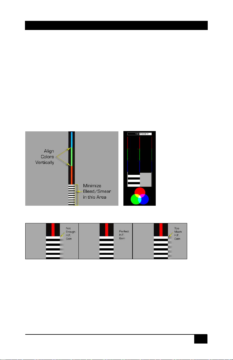
It is best to make this adjustment using a test pattern that is designed
to depict and exaggerate this effect.
Some Hall Research senders may have a built-in test pattern
generator. If your sender unit is equipped with this feature, simply
activate it on the sender. Otherwise, you can connect a PC to the
source and display a test pattern. You can point your browser to
http://www.hallresearch.com/skew.htm
to adjust the compensation and to evaluate the amount of color skew
in your setup.
for an image that allows one
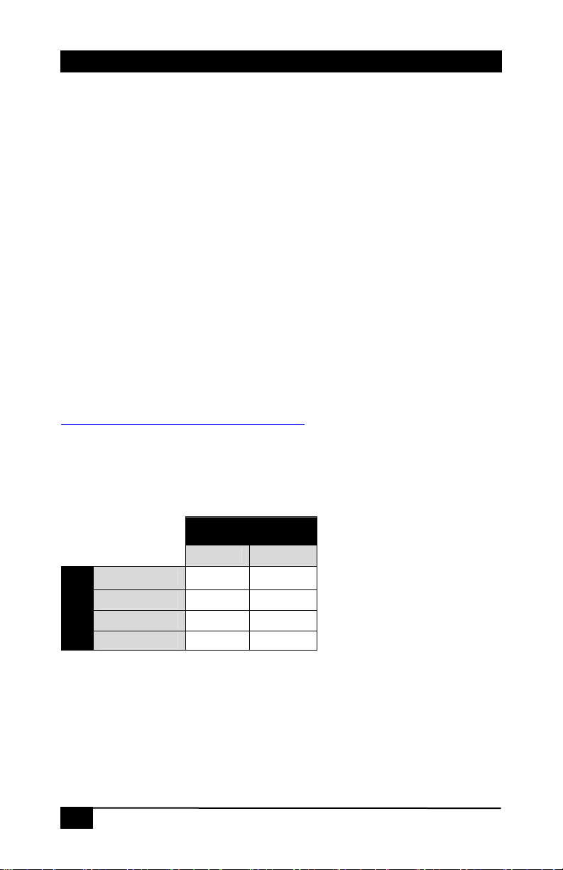
The table below lists the recommended maximum distances from
sender to the receiver depending on the resolution used.
Table 3 -
Recommended maximum
CATx cable length from
sender to the receiver
Resolution
Refresh Rate
60 Hz 75 Hz
800x600 1000 ft 1000 ft
1024x768 1000 ft 850 ft
1280x1024 850 ft 750 ft
1920x1200 750 ft 700 ft
3.2 Compensation Adjustment Procedure
• Press the SEL button once to enter the adjustment-mode
(i.e. without first hitting SEL button the up and down
arrows are inactive).
8
Page 11
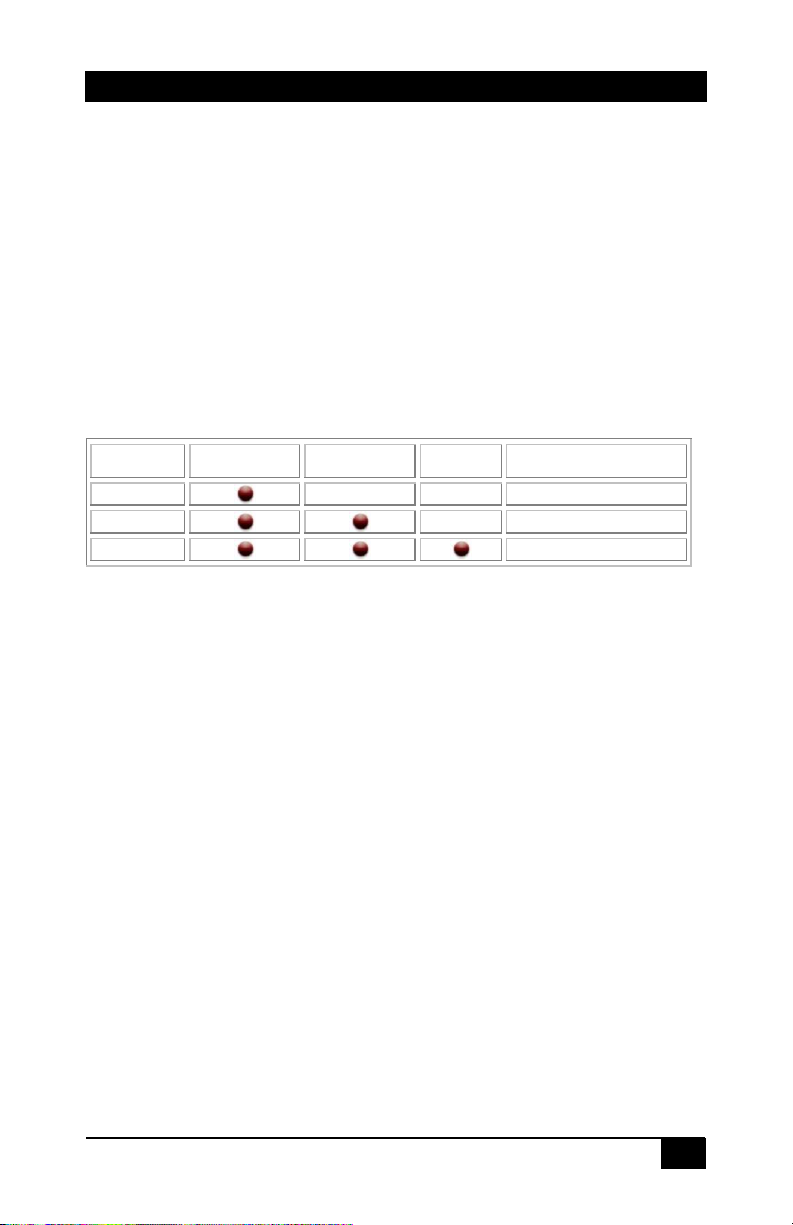
• In adjustment-mode, all 3 LEDs on the unit will be turned
on.
• The UP or DOWN buttons can now be used to adjust the
high frequency (HF) compensation up or down until the
video no longer looks smeared (see figure below).
• Pressing both the UP & DOWN buttons together resets
the current adjustment back to zero. This is a quick way if
you want to start over.
• To exit the adjustment mode at any time, press the SEL
button (the unit also has a built-in timeout to exit this
mode).
PC (VGA) & HD (YPbPr) AV over Twisted-Pair Receivers
Figure 4 - Typical test patterns used for adjusting compensation
Figure 5 - Effect of adjustment on the smearing
3.3 Advanced Adjustment (CATx AWG)
The URA automatically equalizes the brightness of the video as
the smearing is reduced. This automatic adjustment is based on
the assumption that typical 24 AWG CATx cable is being used.
When using 23 AWG CATx cable, then when the smearing is
minimized, your image may be brighter than normal. In many
installations, this is not critical and requires no adjustment;
9
Page 12
Model URA, URA-SKU, & URA-XT
however, for the daisy chain Model (URA-XT), it is important to
set the cable type (23 vs. 24 AWG) that you are using because of
the cumulative nature of the daisy chain.
• In the adjustment-mode, press and hold the SEL button
for at least 3 seconds to enable the WIRE SIZE selection
mode between 23-gauge wire and 24-gauge wire.
• The UP button is used to select 24-gauge wire. The
DOWN button is used to select 23-gauge wire.
• To exit the adjustment mode at any time, press the SEL
button (the unit also has a built-in timeout to exit this
mode).
3.4 Why Skew Adjustment?
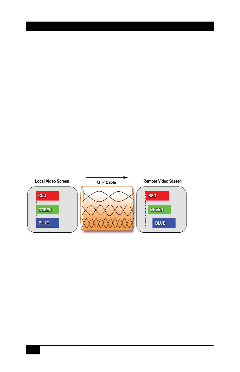
UTP cables have 4 twisted pairs inside. The Hall Research UVA/URA
video transmission on UTP uses 3 individual pairs for each color
(Red, Green, & Blue).
Figure 6 - skew mechanism, explained
As shown in the figure above, a characteristic of Category-5/5e/6
cable is that the pairs of wires are twisted at different rates.
Therefore, for a given length of Cat-6 cable the total length of any
particular pair could be longer than other pairs in the same cable.
Since the signals travel along the length of each pair at a fixed speed,
the arrival times of signals will be skewed in a long cable (those that
have to travel farther arrive later and the corresponding color shifts to
the right).
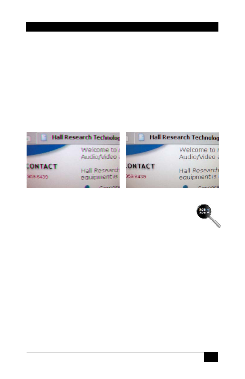
This is seen on the monitor as separation, or lack of convergence in
colors. For example, a vertical white line on the screen may look to
have a red tinge on the left edge and blue tinge on the right edge.
10
Page 13
PC (VGA) & HD (YPbPr) AV over Twisted-Pair Receivers
This effect gets worse at high resolutions, high refresh rates, long
cables (in excess of 200 feet), and depends on the cable construction
itself.
If you are using special UTP cables that are specifically designed for
video transmission (such as Hall Research Zero-Skew™), then there
should be no shift in color alignment regardless of the cable length.
However, in many applications standard and common Cat6 cables
may be utilized, this will necessitate a receiver that can also move
each color component to the left and right in order to realign them.
Models URA-SKU and URA-XT both are capable of doing this. It is
noteworthy that Hall Research also offers a stand-alone skew
corrector unit (Model SKU-RGB).
300 ft of CAT6 (1280x1024 source)
* actual zoomed photo of screen *
After skew adjustment
Figure 7 – Example of Skew manifested
3.5 Skew Adjustment Procedure
This procedure applies to URA-SKU and URA-XT models only.
• Press the SEL button once to enter the adjustment. Press
the SEL button again to light only one of the 3 RGB LEDs.
As you press SEL the Red, Green, and Blue LEDs will
light up one at a time.
• The UP and DOWN buttons are used to move the
selected color component to the left and right. Pressing
both buttons at the same time resets all skew
adjustments.
11
Page 14
Model URA, URA-SKU, & URA-XT
3.6 Signal Adjustment for the Daisy Chain
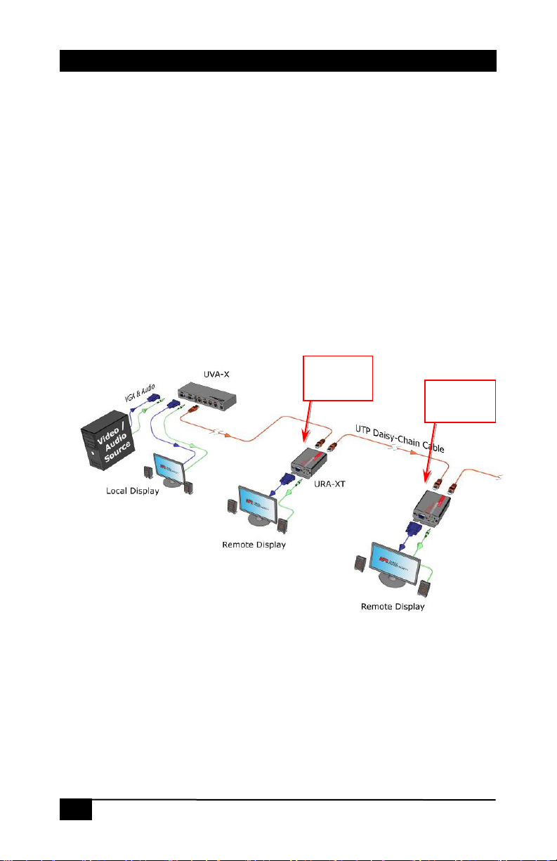
There are no specific procedures for adjusting the URA-XT’s other
than the order the adjustment is made.
The URA-XT’s RJ45 (Cat5) output is the video signal AFTER IT HAS
BEEN ADJUSTED.
This means that the unit closest to the sender has to be adjusted first.
Set the high frequency compensation first and then adjust the skew.
Since the effects in the daisy chain are cumulative, we recommend
that you set the gauge of CATx cable used as well (see section 3.3
above).
Remember, if the calibration is off on a URA-XT in the middle of a
daisy chain and you adjust the device settings you must then check
the rest of the downstream devices and if necessary; make additional
adjustments on those devices as well.
Adjust
First
Adjust
Second
Figure 8 – Daisy-Chain adjustment sequence
12
Page 15
PC (VGA) & HD (YPbPr) AV over Twisted-Pair Receivers
4. Troubleshooting
There are no field serviceable parts or circuits in the device. Opening
the unit will void the warranty. If you think the device is malfunctioning
(or you have no picture output), please try to use the methods
described in Section 4.3 below to obtain a picture first.
4.1 Contacting Hall Research
If you determine that the URA, URA-SKU or URA-XT is
malfunctioning, do not attempt to repair the unit instead, contact Hall
Research Technical Support at 714-641-6607.
Before you do, make a record of the history of the problem. We
will be able to provide more efficient and accurate assistance if
you have a complete description.
4.2 Shipping and Packaging
If you need to transport or ship your unit:
• Package it carefully. We recommend that you use the original
container.
• Before you ship the units back to Hall Research for repair or
return, contact us to get a Return Authorization (RMA) number.
13
Page 16
Model URA, URA-SKU, & URA-XT
4.3 Problem Solving FAQ
1. Fuzzy, blurry, or ghosting image at remote location
If you have a stable image but it looks somewhat blurry
(edges are not sharp), make sure that you have adjusted the
receiver unit’s HF compensation correctly. In addition, check
the recommended table of max distance vs. resolution to see
that you have not exceeded the maximum recommended
cable lengths. If you still have a fuzzy image, try reducing the
refresh rate and/or resolution of the video source.
2. Image exhibits steady or rolling horizontal color “hum”
bars
This is usually an indication of improper grounding at the
sending end, the receiving end, or both. Verify that the AC
line is properly wired and that a protective ground (green)
wire is established with NO potential difference between both
the sender and receiver locations. The UTP splitter can
handle up to 5 volts peak-to-peak of ground noise between
the two locations, but ground potential differences more than
this can show up on video.
3. Shaking image or periodically blanking monitor
Inherently, balanced signal transmission over twisted pair
offers good immunity to EMI coupled noise from other
external sources. However, a strong electromagnetic noise
field can cause instability in the signal.
Usual sources are high power AC lines or data and/or control
cables that run adjacent to and parallel with a substantial
length of the CAT5 cable. To eliminate this, either place a
distance between the CAT5 cables from the splitter and the
interfering source, or use shielded twisted pair (STP) CAT5
cables.
4. Poor audio quality at the receiving end
Only use powered speakers with the splitter and receivers. It
is also good practice to set the audio level (volume) output of
the PC about 1/2 to 2/3 from the maximum and use the
volume knob of the speakers to adjust the volume to the
desired level. A low volume signal output from the PC
reduces the signal-to-noise (S/N) ratio, whereas too high
output amplitude can cause saturation and clipping to occur.
14
Page 17

PC (VGA) & HD (YPbPr) AV over Twisted-Pair Receivers
5. Specifications
Video
Gain Unity
Number/signal type 1 proprietary analog signal input. Standard VGA output
Connectors 1 female RJ-45 input, 1 HD15 output
Nominal amplitude 1 V p-p for Y of component video
Impedance 75 ohms
Skew compensation 62 ns
Maximum resolution Up to 1920x1200 and 1080p at 750 ft; 1280x1024 at 850 ft
Polarity Positive or negative
Audio
Gain Unbalanced output: 0 dB
Frequency response 20 Hz to 20 kHz, ±1 dB
Connector (1) 3.5 mm connector
Type Monaural, Simulated Stereo
THD + Noise 0.2% @ 1 kHz, 0.3% @ 20 kHz at nominal level
General
Recommended cable CAT 5/5e/6 (shielded or unshielded) for URA-XT and URA-
Power Supply 100 VAC to 240 VAC, 50-60 Hz, external; 5 VDC, 2 A,
Temperature/humidity Storage: -40 to +158 °F (-40 to +70 °C) / 10% to 90%, non-
Cooling Convection, vents on each end
Mounting Brackets at each end with screw hole provided for Wall or
Enclosure type Metal
Dimensions 1.18" H x 2.75" W x 3.85" D - Depth excludes connectors
Product weight 0.75 lb (0.35 kg)
Shipping weight 1.5 lbs (0.70 kg)
Vibration ISTA 1A in carton (International Safe Transit Association)
Safety CE
EMI/EMC CE, FCC Class A
MTBF 90,000 hours
Warranty 2 years parts and labor
RGBHV, RGBS, RGsB, RsGsBs, component video (bi-/tri-level
sync)
0.7 V p-p for RGB and for Pr and Pb of component video
4.0 V to 5.0 V p-p, for TTL Sync signals of RGBHV, RGBS
SKU
regulated; 2.1mm
condensing
Operating: +32 to +122 °F (0 to +50 °C) / 10% to 90%, noncondensing
Rack mounting
(30 mm H x 70 mm W x 98 mm D)
Specifications are subject to change without notice
15
Page 18

Model URA, URA-SKU, & URA-XT
16
Page 19

Page 20
CUSTOMER
SUPPORT
INFORMATION
© Copyright 2009. Hall Research, Inc.
All rights reserved.
Order toll-free in the U.S. 800-959-6439
FREE technical support, Call 714-641-6607 or fax 714-641-6698
Mail order: Hall Research, 1163 Warner Ave. Tustin, CA 92780
Web site: www.hallresearch.com E-mail: [email protected]
 Loading...