

Page 1

Model U97-ULTRA
All-in-One UTP Console Extender
Dual Video, Audio, RS-232, with
General Purpose USB, and up to 2 Direct USB Extensions
Order toll-free in the U.S. 800-959-6439
FREE technical support, Call 714-641-6607 or fax 714-641-6698
Mail order: Hall Research, 1163 Warner Ave. Tustin, CA 92780, CA 92704
Web site: www.hallresearch.com
CUSTOMER
SUPPORT
INFORMATION
UMA1158 Rev. D
Page 2

Page 3

TRADEMARKS USED IN THIS MANUAL
Hall Research, HR, and the logo are trademarks of Hall Research Inc.
Windows™ is a trademark of Microsoft Corporation.
Any other trademarks mentioned in this manual are acknowledged to be the
property of the trademark owners.
FEDERAL COMMUNICATIONS COMMISSION
RADIO FREQUENCY INTERFERENCE STATEMENT
This equipment generates, uses, and can radiate radio frequency energy and if
not installed and used properly, that is, in strict accordance with the
manufacturer’s instructions, may cause interference to radio communication. It
has been designed and tested to comply with the limits for a Class A computing
device in accordance with the specifications in Subpart B of Part 15 of FCC
rules, which are intended to provide reasonable protection against such
interference when the equipment is operated in a commercial environment.
Operation of this equipment in a residential area is likely to cause interference.
In which case the user at their own expense will be required to take whatever
measures may be necessary to correct the interference.
This equipment is CE, FCC and CSA certified.
,
CSA Certified file # 246552
(Complies with UL 60950-1, Second Edition U.S. Standards)
Product Designed and Tested to Support Microsoft Windows
2000/XP/Vista/7
Page 4

Model U97-ULTRA
4
Table of Contents
About this User’s Manual
......................................................................................... 5
1.0 General
....................................................................................................... 6
1.1 Catx Cable Requirements
........................................................................... 6
1.2 RJ45 Port Functions
................................................................................... 7
1.3 User I/O Connector Descriptions
............................................................... 7
1.4 Features
...................................................................................................... 9
2. Installation
........................................................................................................ 10
2.1 Connecting the Sender to the PC
.............................................................. 10
2.2 Connecting the Sender local outputs
........................................................ 12
2.3 Connecting the Sender to the Receiver
.................................................... 12
2.4 Connecting the Receiver outputs
.............................................................. 13
3. Configuration & Operation
.................................................................................. 14
3.1 Sender Front Panel Controls and indicators
............................................. 14
3.2 Receiver Front Panel Controls and indicators
........................................ 14
4. Receiver Cover
................................................................................................. 18
5. Troubleshooting
................................................................................................ 19
6. Specifications
.................................................................................................... 20
CAUTION:
CONTAINS HAZARDOUS VOLTAGES
NO USER SERVICEABLE PARTS INSIDE.
ATTENTION: TENSION DANGEREUSE, L'APPAREIL
NE COMPORTE AUCUN ÉLÉMENT QUE
L'UTILISATEUR PUISSE RÉPARER
Page 5

Console Extender
5
About this User’s Manual
This User’s Manual pertains to the Model U97-ULTRA-2 console extender kit. Please
refer to the Block Diagram on the following page. This device is used to extend Dual PC
Video (VGA), Audio (amplified or line level), full-duplex RS-232, one general purpose
USB port (STD) with a 2-port hub at the sender and a 4-port hub at the receiver, and two
additional direct-link (hubless) USB extensions (DR1 & DR2).
The product is commonly sold as a kit which includes a rack-mountable sender unit plus
a wall-mountable Receiver (and I/O hood cover), packaged together. However they can
also be sold separately.
The table below lists the various configurations and part numbers.
Model Number
Description
U97-ULTRA-2
Kit for 1 general purpose USB (STD) and 2 direct (DR1 and
DR2) USB Extensions, plus Dual Video, Audio, and RS-232
Kit includes one Receiver and one Sender per below part
numbers
U97-ULTRA-2R
Receiver (Remote) Unit - Peripheral Extender with 2 direct
USB Ports (DR1 & DR2)
U97-ULTRA -2S
Sender (Local) Unit - Peripheral Extender with 2 direct USB
Ports (DR1 & DR2)
These products are manufactured by Hall Research to highest quality control standards. All units
are fully tested (including Hi-Pot leakage), undergone 24 to 48 hours of burn-in, and re-tested prior
to delivery.
Page 6

Model U97-ULTRA
6
1.0 General
U97-ULTRA-2 kit is used to extend Dual Display PC Video, Stereo Audio, RS-232, and
up to 3 independent USB ports to a remote location up to 400 feet away on any Category
Cable (CAT5e/6 etc). A block diagram of the system is shown below.
Block Diagram (see Specifications for a full-page image)
1.1 Catx Cable Requirements
Depending on the model or application from 2 to 4 UTP (CATx) cables are needed to
connect the sender to the receiver.
Extension Requirement
Number of CATx Cable and Connector Position
Dual Head Video
Audio, RS232
USB: Std (Hub), DR1, DR2
4 UTP : A, B, C, D
Dual Head Video
Audio, RS232
USB: Std (Hub), DR1
3 UTP : A, B, C, D
Single Video
Audio
USB: Std (Hub), DR1
2 UTP : A, C
It is recommended to use CAT6 UTP or STP since it offers the maximum extension
capabilities. The unit is capable of extending all the signals to over 400 feet (approx. 450
feet using Cat6 UTP Cables). Zero or low-skew cables are not needed since the device
incorporates skew correction on both video channels.
Video A
Video B
RS-232
Audio
USB STD
USB DR1
USB DR2
Video A
Video B
Audio
USB Local 1
USB Local 2
USB Hub
Video A
Video B
Audio
USB KBRD 1
USB Mouse 2
USB Hub
Cat x Drivers
Port A
Port B
Port C
Port D – For DR2 Only
Cat x Cables
Cat x Receivers
USB AUX 3
USB AUX 4
USB DR1
USB DR2
RS-232
Receiver
Sender
Local
Outputs
Page 7

Console Extender
7
1.2 RJ45 Port Functions
The RJ45 connectors are labeled Port A though Port D, functions carried via each port is
listed below. This chart is useful for trouble shooting purposes.
Port
Signals Extended
Comments
A
Video A, Audio, Calibration Switch state
Required in all applications
B
Video B, RS-232
May be omitted of Video B or RS-232
extension is not needed.
C
General Purpose USB and DR1 USB
Required in all applications
D
DR2
Only present on -2K with DR2. May
be omitted if DR2 is not used
1.3 User I/O Connector Descriptions
The Sender provides connectors for connection to the PC source and features local
outputs at of both video ports, audio signals (with amplified audio pass-through), and
General Purpose USB port (for connection to local keyboard or pointing devices). Please
refer to the block diagram.
VGA A IN & VGA B IN – These are PC’s video input signals (VGA thru UXGA)
with local loop outputs at the sender. They are extended to a remote unit
through RJ45 Port A and Port B. High Frequency (HF) and RGB skew
compensation is incorporated at the receiver to provide a brilliant image for
these video signals.
Audio – DB15 connector (with 2 rows of pins) for audio input and a loop output
at the sender. The audio is extended to a remote receiver which has both line
as well as Powered outputs (for driving passive speakers). The DB15 audio I/O
allows interface with not only line-level 3.5 mm mini-stereo audio sources
(using adapter cable available from Hall Research), but it also provides a more
reliable and secure means for the audio connection through use of gold-plated
D-Sub connector with jack screws. The audio input level supports a wide
range of standards; it could be amplified (for driving passive speakers), +4dBu
(Pro-Audio), or -10dBv (consumer line-level).
USB STD – This is a general-purpose USB Port, which goes through a hub in
the sender and provides 2 USB local output ports. It is also extended to the
remote receiver, in which another hub provides the user 4 USB ports. These
USB ports are labeled as KBRD 1, MOUSE 2, AUX 3, and AUX 4. These
Page 8

Model U97-ULTRA
8
general-purpose USB ports support any type of low-speed or high-speed USB
devices. AUX 3 and AUX 4 are typically used for touch screen displays, but
support all other USB devices as well.
DR1 & DR2 – These are two “Direct” extension USB ports. The corresponding
USB port on the PC is directly extended to a remote receiver with no hubs or
other functions in the path. The PC’s USB port that is extended via DR1 or DR2
behaves exactly as if it were connected directly to the target device at the
remote. These “Direct” USB port extensions are perfect for high data rate
devices, such as video cameras, storage media, printers and chart recorders.
They do not support low-speed “Human Interface” devices, such as keyboard
or mouse. Having a dedicated path from the target device to the PC ensures
full channel bandwidth availability in the interface (as opposed to several
devices sharing one port on the PC via a hub).
Serial RS-232 – Bi-directional extension of RS-232 data.
Both the sender and the receiver have built-in power supplies with standard IEC320 jacks
(no external power bricks). The sender includes 6 ft cables for connection to the PC (3x
USB, 2x VGA, 1x DB15 audio). The sender also includes rack-mount front panel. The
receiver includes a metal guard that covers all the connections, thereby eliminating the
need for a separate utility box.
Both the sender and the receiver have DB15 output connectors for the sound so that
standard 4 or 8-Ohm passive speakers can be directly connected at both ends.
Page 9

Console Extender
9
1.4 Features
• Combines the functions of Hall Research Models U97-H2, UU2X4-P1, two SKU-
RGB, DVC-3 video test pattern generator, and more
• Eliminates the need for Utility Box (Receiver includes a guard plate that goes over all
the connectors with tie-down provisions for strain relief)
• Does not require external power supply (built-in supply with standard 110~240 VAC
IEC320 jack)
• Includes 2 “Direct” USB ports (DR1 & DR2), and a Standard with Hub at both ends.
• DB15 connector for audio input and loop output at the sender as well as DB15 output
at the receiver. Receiver features a DB15 Male output with amplified output to drive
passive speakers directly, as well as line level 3.5mm jack for powered speakers.
• Built-in video Skew Correction on both video channels. This corrects the lack of RGB
convergence when long Cat6 cables are used. Eliminates the need to use special
low-skew UTP cables for long runs.
• Built-in Test pattern generator for long cable compensation (High Frequency Gain)
and Skew correction.
• Built-in EDID (Extended display ID), allows PC to detect LCD’s even if none is
connected at the sender or the receiver.
• Local USB outputs at the sender for connection of local keyboard and mouse.
• Supports hot-unplug and hot-plug of USB Peripherals (General Purpose USB ports,
as well as DR1 and DR2)
Page 10

Model U97-ULTRA
10
2. Installation
2.1 Connecting the Sender to the PC
Using the supplied cables; connect the sender to the PC.
Sender Rear Panel
Close-up of Sender Input Connections
Close-up of Sender UTP Connections to the Remote Unit
Connect PC’s VGA outputs to VGA A IN and VGA B IN connectors using the supplied
cables.
Connect the audio source to AUDIO connector using the furnished DB15 male-to-female
cable. Below is a diagram of the sender’s audio input connector and pass-through audio
output. When connecting to a 3.5mm source use adapter part number CA10084 (sold
separately see drawing below).
As seen in the attached schematic diagram, the unit only utilizes and passes through the
amplified audio pins of the DB15 input connector. The audio input pins and
corresponding return pins are kept isolated in the sender (high impedance).
Page 11

Console Extender
11
Audio/Speaker Connections at the Sender
Speaker Cable CA10084 - for connection to 3.5 mm source
Page 12

Model U97-ULTRA
12
USB Port & Connector Types
If a serial communication is needed, connect a PC’s serial port to RS232, a DB9 female
connector. Usually a straight-thru DB9 M/F cable is required (not supplied).
Use the included USB cables to connect the PC to USB STD and DR1 connectors.
These are Type ‘B’ connectors, which are used to attach the USB cable to a USB device.
The opposite end of the USB cable uses Type ‘A’ connectors which connects a USB
device to a PC or a USB hub. The figure below shows two different types of USB
connector.
2.2 Connecting the Sender local outputs
The sender has buffered outputs for connection of two LCD’s, a passive speaker, and
two USB devices (commonly keyboard and mouse or a KVM Switch).
Sender Local Output Connections
2.3 Connecting the Sender to the Receiver
Depending on the specific need you need from 2 to 4 UTP cables to connect the sender
to the receiver, please refer to table on page 6.
Page 13

Console Extender
13
Sender RJ45 outputs to Receiver
Port A of the UTP carries VGA A and AUDIO signals
Port B of the UTP carries VGA B and Bi-directional RS232 signals
Port C of the UTP carries the Standard (STD) USB and the “Direct” USB port DR1.
Port D of the UTP carries the “Direct” USB port DR2
2.4 Connecting the Receiver outputs
The receiver outputs are shown below.
Receiver Rear Panel
Connect display devices such as two LCD’s to the VIDEO ‘A’ & VIDEO ‘B’ connectors of
the receiver.
Connect a LINE AUDIO OUT from the receiver to any standard PC external speakers
(powered) using male to male 3.5mm audio patch cable.
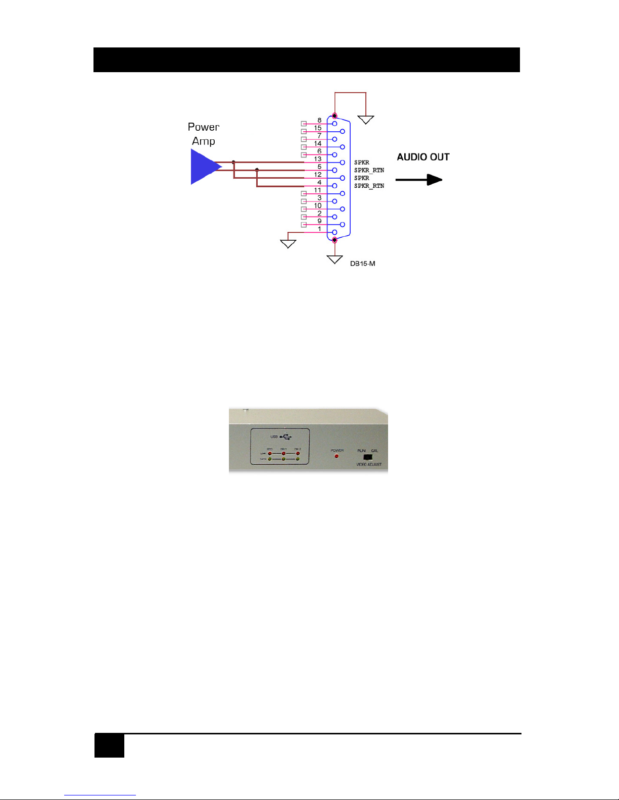
If an amplified audio output level is desired, connect the receiver’s PWR AUDIO OUT
connector to the desired device. The pin diagram of the receiver’s PWR AUDIO OUT is
shown below. For reference also see CA10084 diagram above.
Page 14
Model U97-ULTRA
14
Receiver Audio Output Connector, DB15 – Female
If a serial communication is needed, connect a PC’s serial port to RS232, a DB9 male
connector
3. Configuration & Operation
3.1 Sender Front Panel Controls and indicators
Keep the VIDEO ADJUST switch in RUN mode for normal operation. Set it to CAL
(calibrate) mode to adjust the video at the remote unit per the following descriptions
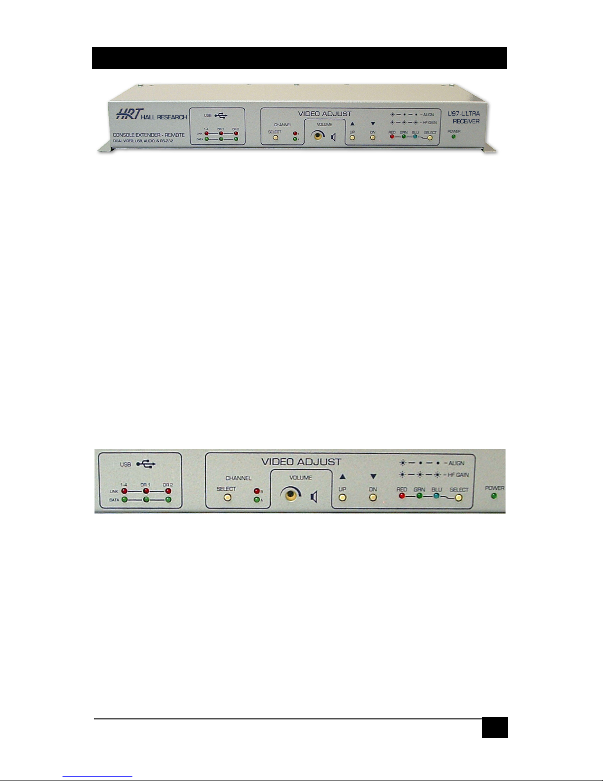
3.2 Receiver Front Panel Controls and indicators
The Console Extender-Remote unit can be operated in two different modes, which are
run-mode and calibrate-mode.
In the run-mode, all LEDs and buttons for video adjust are off.
In the calibrate-mode, the unit should turn on the specific video adjust LEDs to indicate
the previous selection in this mode, such as channel selection A or B, HF Gain or Align
mode.
Page 15
Console Extender
15
There are two ways to get into the calibrate-mode to adjust the video. The first and
recommended method is to use the VIDEO ADJUST switch on the sender and set it to
CAL, which puts the receiver in the calibrate mode and also activates a test pattern. The
receiver stays in this calibrate-mode until the VIDEO ADJUST switch is set back to RUN.
The other way to enter the calibrate-mode is to hold down the SELECT button for 3
seconds at the receiver, in this case the test pattern will not be displayed as output. If
there is no user activity on the front panel for 1 minute, the receiver will time out and
switch back to the run-mode.
Note
The VIDEO ADJUST switch on the sender can be used to quickly put
the receiver in the calibrate-mode (Video Adjust LED’s on the
Receiver front panel are lit). The sender also generates a test pattern
that is specifically designed for Video Calibration.
The CHANNEL SELECT button is used to select either video A or video B input source
to adjust. The setting for Ch A and B are independent and hence the procedure must be
repeated for each of the 2 video screens.
The UP and DN buttons are used to adjust either the High Frequency compensation (HF
GAIN) or the red, green, and blue signal alignment (ALIGN). The UP or DN button can
be pressed once to increment or decrement the gain level. When holding down either
the UP or DN button, the unit will automatically increment or decrement the gain level
until it reaches the max or the min gain level setting. The RED, GRN, & BLU LEDs will
flash when the unit’s gain level is at min or max. The UP and DN buttons can also be
used to reset the HF Gain or the signal alignment. Just press them simultaneously.
The SELECT button is used to select either the signal alignment (ALIGN) or the high
frequency gain (HF GAIN) adjustment.
Page 16

Model U97-ULTRA
16
The following figures show how an image can be adjusted to become perfect by using
the receiver front panel controls.
Test Pattern for HF Gain and Skew adjustments
Select the video channel that you are going to adjust. Start by adjusting HF gain (all 3
LED’s on the Receiver lit). It is best to start at the min compensation setting. To do this
either press the Down button repeatedly until the LED’s blink (indicates you are at min),
or simply press both Up and Down buttons simultaneously.
If the cable is long then the black and white horizontal lines tend to appear smeared
(black smears as black, and white as white). Press the Up button one at a time paying
particular attention just to the right of the horizontal lines. Your goal is to make the
transition are between the horizontal black and white lines and the 50% grey background
have as little smear as possible. Do not over adjust. If you do, some smear comes back
particularly near the transition but in reverse sense (white lines smear into grey as black
and vice versa).
The following images depict the adjustment results as seen on the screen:
Page 17

Console Extender
17
HF gain adjustment (zoomed view)
Once you have adjusted the HF Gain, hit the select button to cycle through the Red,
Green and Blue colors and use the Up and Down buttons to align the colors vertically.
When you are all done, if you had initiated the calibration by using the Calibration switch
on the sender, you should go back to the sender and put the switch in the Run mode.
The Receivers Calibration LED’s will go out and the buttons will not be operative.
The output audio volume level can be manually adjusted by using a small flat-screw
driver to turn a recessed pot clockwise for louder or counter-clockwise for softer. You
cannot turn the volume all the way down. This means that even if the pot is turned fully
CCW, you still have some audio output.
Page 18
Model U97-ULTRA
18
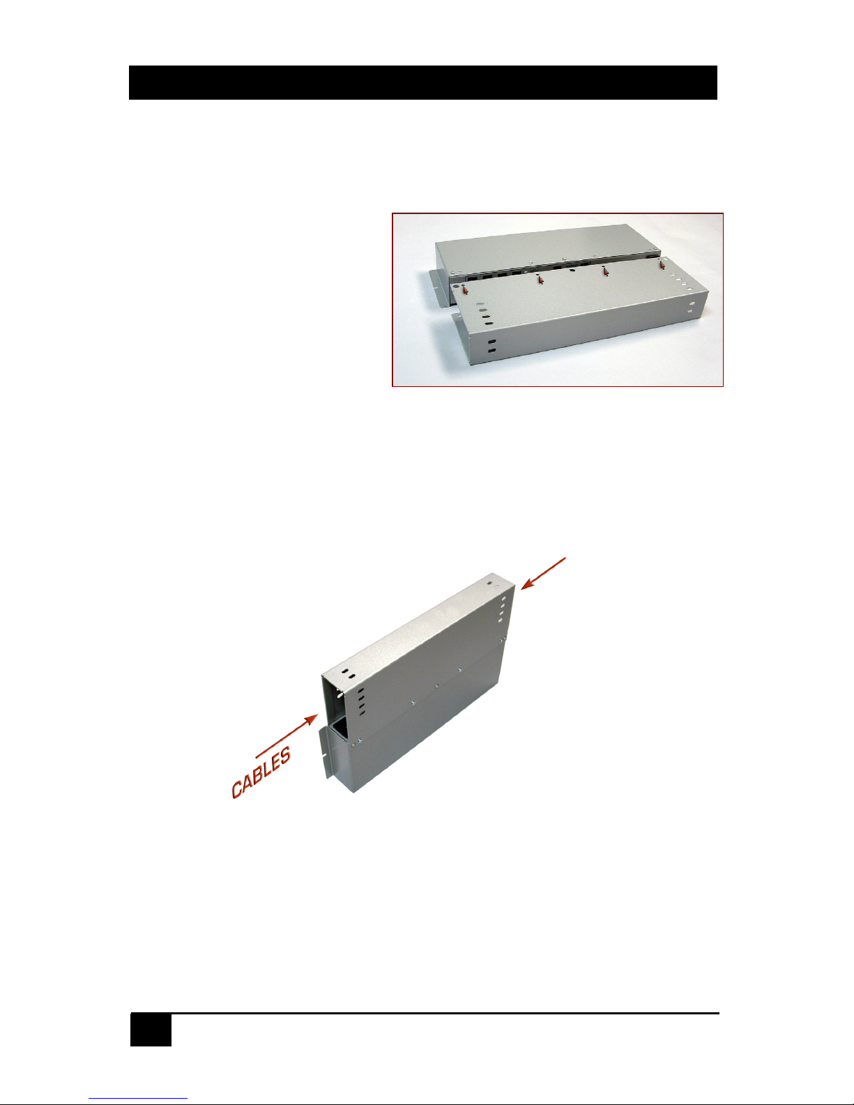
Locations of attachment holes for screws
Cables can enter and leave from either end
4. Receiver Cover
In the diagram below the location of holes where the cover screws to the receiver are
shown with little arrows. All screws
are provided with the unit. There are
4 screws on the top and 2 on the
bottom (not shown).
You can use the slotted holes at
either end of the unit to zip-tie the
cables in place.
Once the cover is firmly attached and
cables zip-tied in place, you can screw
the entire assembly to a suitable base
using the L flanges on either side of
the unit.
Make sure that the front panel is accessible for skew and or video adjustments as
needed.
Page 19

Console Extender
19
5. Troubleshooting
Make sure that all connections to the PC and peripheral equipment are solid. Reboot the
PC if any of the connections were loose as this may have caused the PC to lock up.
If the problem is related to the video, check the function and calibration by placing the
unit is Calibration mode using the switch on the sender. If the image on the display is not
centetred properly, use the LCD’s on screen display to do an Auto Adjust Image.
If the problem is with the USB devices, check the state of the LED’s on the front panel of
the each unit. These LED’s pertain to USB links. The General purpose USB (STD) link
light should be on if proper connection is made between the sender and the receiver,
Data light will light if connection to PC is made and adevice is plugged to one of the STD
USB ports on the remote unit. The DR1 and DR2 leds function when the sender is
connected to the PC
and
the receiver at the remote is connected to a USB device (such
as a printer) therefore link and data LEDs work together. If connection to the PC of DR1
or DR2 is verified, but the Link and Data leds are off, unplug the corresponding device
from the remote, wait 5 seconds and plug it back in.
Check the RJ45 port connections (A to A, B to B, etc), make sure they are not crossed,
loose, or disconnected. Use the following chart to narrow your attention depending on
device you are having trouble with:
Port A of the UTP carries VGA A and AUDIO signals
Port B of the UTP carries VGA B and Bi-directional RS232 signals
Port C of the UTP carries the Standard (STD) USB and the “Direct” USB port DR1.
Port D of the UTP carries the “Direct” USB port DR2
If you cannot trouble shoot the setup, please note all pertinent symptoms and make a list
of any other equipment used in the setup.
Do not open or try to repair the unit yourself. There is no customer repairable item in the
unit and you will void the warranty.
Contact Hall Research Technical Support Department at 714-641-6607 or via email or
web. If you need to ship your switch for repair, make sure to get a Return Material
Authorization (RMA) number first.
CAUTION: CONTAINS HAZARDOUS VOLTAGES
NO USER SERVICEABLE PARTS INSIDE.
ATTENTION: TENSION DANGEREUSE, L'APPAREIL NE COMPORTE
AUCUN ÉLÉMENT QUE L'UTILISATEUR PUISSE RÉPARER
Page 20

Model U97-ULTRA
20
6. Specifications
Video Inputs PC outputs (VGA to UXGA)
Video
Resolutions PC resolutions up to 1920x1280 @ 60 Hz
Video Levels 0 to 0.7v p-p
Sender 1.5” High x 19” Wide x 5.06” Deep
Dimensions
Receiver 1.75” High x 14” Wide x 4.06” Deep
Sender 4 lbs
Weight
Receiver 3 lbs
USB Support High Speed devices (12Mb/s)
Others
Low Speed devices (1.5Mb/s)
UTP Cable Up to 400 feet using any Cat5e or 450 ft using Cat6
Temperature Operating: 32 to 122°F (0 to 50°C);
Storage: -40 to +185°F (-40 to +85°F)
Enclosure Steel
MTBF 90,000 hours (calculated estimate)
Power 100VAC – 240VAC 50/60Hz
Page 21

Console Extender
21
Block Diagram of the U97-ULTRA-2
Extender Kit
Page 22

Model U97-ULTRA
22
Page 23

Page 24

© Copyright 2010. Hall Research, Inc.
All rights reserved.
1163 Warner Ave., Tustin, CA 92780
Ph: (714)641-6607, Fax: (714)641-6698
 Loading...