

Page 1

Hall Research DS Manager
DS Manager IP Setup
For use with Hall Research Products
Table of Contents
1. Introduction ..........................................................................................1
1.1 General.........................................................................................1
2. Installation............................................................................................2
2.1 Download the DS Manager Installation.......................................2
3. Configuration........................................................................................3
3.1 Ethernet Configuration ................................................................ 3
3.2 Settings ........................................................................................ 3
4.5 Access via Port 23 and Port 1001 or 6324...................................4
5. Troubleshooting....................................................................................7
5.1 Contacting Hall Research ............................................................ 7
5.2 Shipping and Packaging ..............................................................7
Hall Research Inc.
Home of the Mini-Cat®
1. Introduction
1.1 General
Many Hall Research products are IP enabled allowing communications across
a LAN network to communicate with the product. Some products are shipped in
DHCP mode which allows the customers network to assign an IP address.
Other products are shipped with a static IP address. Consult the product
documentation for more information.
To find the Hall Research device on your compatible LAN network requires the
use of the DS Manager utility. This small Windows™ based utility scans the
local network and displays a list of all compatible devices found.
1
Page 2
Hall Research DS Manager
2. Installation
2.1 Download the DS Manager Installation
Access the Hall Research product webpage and download the appropriate 32
or 64 bit Windows™ application.
Unzip and execute the installation program.
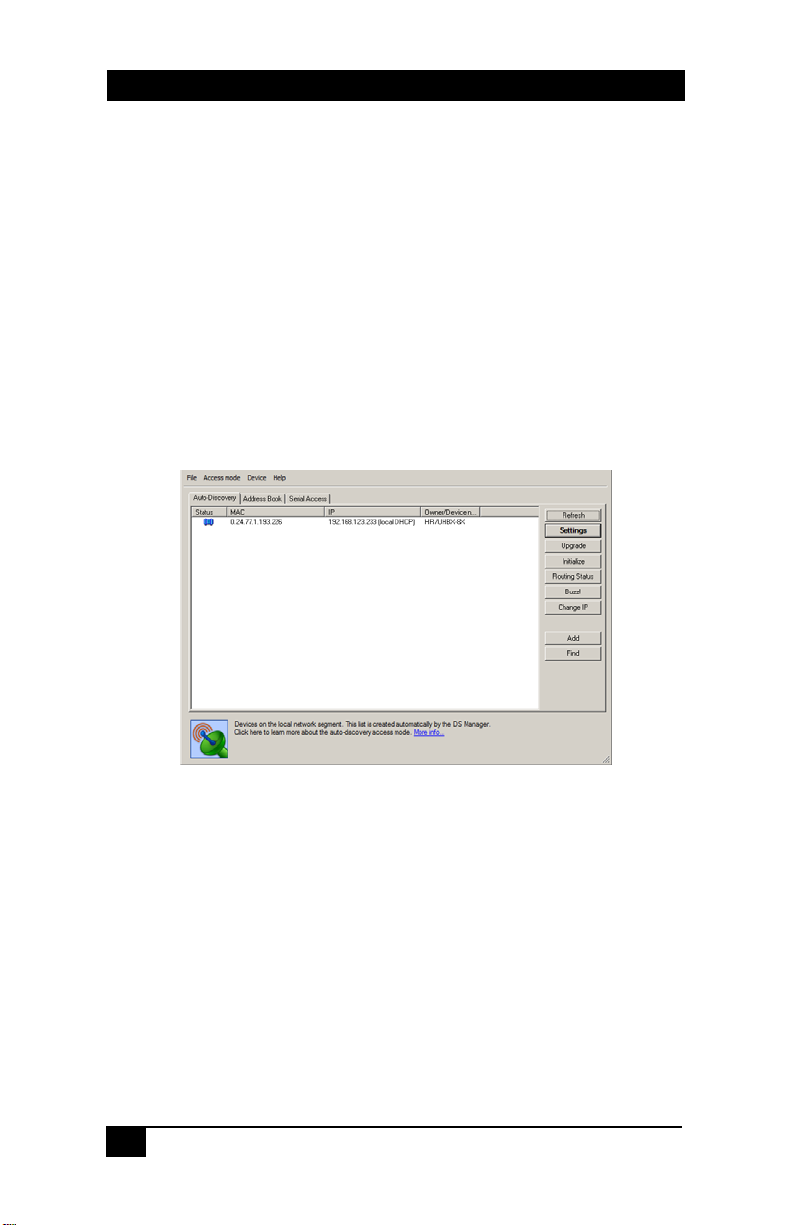
Run the DS Manager application
A window similar to below is displayed with a list of all compatible devices
found.
If no devices are listed, click the REFRESH button. If no devices are listed,
contact you IT administrator to ensure that all the proper network settings are
in place.
2
Page 3

Hall Research DS Manager
3. Configuration
3.1 Ethernet Configuration
If the configuration of the end users LAN is compatible with the default
settings, then the user is not required to make changes to the Ethernet
Configuration.
If the configuration is not compatible, use the DS Manager to change the
unit’s configuration.
Set the IP Address to any STATIC unused address available on the endusers network.
The IP Address of the model must be in the same subnet as any computer
attempting to access the device. If the computer attempting to access the
device is on another network subnet, then the end-user is responsible for
configuring any network routers or switches necessary to allow access to
the devices IP Address on Ports 23 and 1001. Contact your network IT
administrator for assistance with these settings.
Set the Gateway Address to the required IP Address of the end-users
Gateway. If the end-user will always access the device from a computer
connected on the same network node, then the Gateway Address may be
left at its default value. Contact your network IT administrator for
assistance with these settings.
Set the Net Mask to the required values compatible with the end-users
network. If the end-user will always access the device from a computer
connected on the same network node, then the Net Mask may be left at its
default value. Contact your network IT administrator for assistance with
these settings.
3.2 Settings
The user must select the desired device and click the “SETTINGS” button to
obtain access to that device’s configurable parameters.
To change a parameter, click on the field next to the parameter’s name and
enter the appropriate information.
Click the OK button when finished and the information will be uploaded into the
device. There will be a short time delay while the device reboots.
3
Page 4

Hall Research DS Manager
4.5 Access via Port 23 and Port 1001 or 6324
A HyperTerminal TCP/IP connection can be used to access either PORT 23 or
1001.
Either Port 1001 or 6324 is used for the RS232 communication
through the device. All communication occurs at the baud rate that
the device is currently configured for. The LAN connection Baud
Rate must match the speed being used by the RS232 ports for
meaningful communication to occur. Consult the product manual for
more information.
Port 23 can be used to change specific parameters in the device
such as its IP Address, Gateway Address, Baud Rate…etc.
To run a HyperTerminal window, open the application and set it up for TCP/IP
connection on PORT 23 along with the device IP address as the host address.
Commands to PORT 23 have the following format and replies:
STX Command/Reply CR
STX character (ASCII code 0x02 or CTRL-B from the keyboard)
The unit will respond with the following codes indicating the status of the
command requested. Anything other than ‘Accepted’ indicates a problem with
that command/connection to the VSA-31-IP Module:
<^B>A means Accepted
<^B>C means Error
<^B>R means Rejected
<^B>D means Denied
<^B>F means Failed
<^B>S means Bad Sequence
In the following table, the following notations are used:
<^B> denotes the STX Character, 1 Byte of 0x02
<CR> denotes the CR Character, 1 Byte of 0x0D
<^B>L<CR> Log Into Module <^B>A<CR>
<^B>O<CR> Log Out of
<^B>E<CR> Reboot Module None IP Connection
Command Purpose Reply Notes
Module
<^B>A<CR>
to module will
be lost
4
Page 5

Hall Research DS Manager
<^B>GFE<CR> Get Modules
<^B>SFExxx.xxx.xxx.xxx.xxx.xxx<CR>
Where xxx.xxx.xxx.xxx.xxx.xxx represents the
MAC Address
<^B>GIP<CR> Get Modules IP
<^B>SIPaaa.bbb.ccc.ddd<CR>
Where aaa.bbb.ccc.ddd represents the IP Address
<^B>GPN<CR> Get Modules Port
<^B>SPNaaaaa<CR>
Where aaaaa represents the Port Number
<^B>GGI<CR> Get Modules
<^B>SGIaaa.bbb.ccc.ddd<CR>
Where aaa.bbb.ccc.ddd represents the Gateway
Address
<^B>GNM<CR> Get Modules
<^B>SNMaaa.bbb.ccc.ddd<CR>
Where aaa.bbb.ccc.ddd represents the SubNet
Mask
<^B>GBR<CR> Get Modules
<^B>SBRaa<CR>
Where aa represents the Baud Rate as follows:
0 = 1200 5 = 38400 10 = 600
1 = 2400 6 = 57600 11 = 28800
2 = 4800 7 = 115200
3 = 9600 8 = 150
4 = 19200 9 = 300
<^B>GPR<CR> Get Modules
Command Purpose Reply Notes
MAC Address
Set Modules MAC
Address
Address
Set Modules IP
Address
Number
Set Modules Port
Number
Gateway Address
Set Modules
Gateway Address
SubNet Mask
Set Modules
SubNet Mask
Baud Rate
Set Modules
Baud Rate
Parity
<^B> xxx.xxx.xxx.xxx.xxx.xxx<CR>
Where xxx.xxx.xxx.xxx.xxx.xxx
represents the MAC Address
<^B>A<CR>
<^B>Aaaa.bbb.ccc.ddd<CR>
Where aaa.bbb.ccc.ddd represents
the IP Address
<^B>A<CR>
<^B>Aaaaaa <CR>
Where aaaaa represents the Port
Number from 0 to 65534
<^B>A<CR>
<^B>Aaaa.bbb.ccc.ddd<CR>
Where aaa.bbb.ccc.ddd represents
the Gateway Address
<^B>A<CR>
<^B>Aaaa.bbb.ccc.ddd<CR>
Where aaa.bbb.ccc.ddd represents
the SubNet Mask
<^B>A<CR>
<^B>Aaa <CR>
Where aa represents the Baud Rate
as follows:
0 = 1200 5 = 38400 10 = 600
1 = 2400 6 = 57600 11 = 28800
2 = 4800 7 = 115200
3 = 9600 8 = 150
4 = 19200 9 = 300
<^B>A<CR>
<^B>Aaa <CR>
Where aa represents the Parity as
follows:
0 = Off or None
1 = Even
2 = Odd
3 = Mark
4 = Space
1st Digit must
be EVEN.
Must
REBOOT for
changes to
take effect
It is
recommende
d that the
MAC address
not be
changed
Must
REBOOT for
changes to
take effect
Defaults to
1001
Must
REBOOT for
changes to
take effect
Must
REBOOT for
changes to
take effect
Must
REBOOT for
changes to
take effect
Must
REBOOT or
LOG OUT for
changes to
take effect
5
Page 6

Hall Research DS Manager
<^B>SPRaa<CR>
Where aa represents the Parity as follows:
0 = Off or None
1 = Even
2 = Odd
3 = Mark
4 = Space
<^B>GBB<CR> Get Modules
<^B>SBBaa<CR>
Where aa represents the Data Bits per Byte as
follows:
0 = 7
1 = 8
Command Purpose Reply Notes
Set Modules
Parity
Serial Data Bits
Per Byte
Set Modules
Serial Data Bits
Per Byte
<^B>A<CR>
<^B>Aaa <CR>
Where aa represents the Data Bits per
Byte as follows:
0 = 7
1 = 8
<^B>A<CR>
Note on IP Settings via port 23
If you are unable to access the unit’s
port 23 from your PC using the IP
Modules default or last known IP
address, it could be that the IP address
of the IP Module is not compatible on
your LAN. One way around this is to
connect your PC directly to the IP
Modules RJ45 port using a cross over
cable, or use a switch or router not
connected to anything else but your PC
and the IP Module, and then configure
your PC for a static IP address
compatible with the current address of
the IP Module. If the IP Module has the
factory default of 192.168.123.199, a PC address of
192.168.123.nnn may be entered where nnn is any
number except 199.
Must
REBOOT or
LOG OUT for
changes to
take effect
Must
REBOOT or
LOG OUT for
changes to
take effect
6
Page 7

5. Troubleshooting
Hall Research DS Manager
5.1 Contacting Hall Research
If you determine that your device is malfunctioning, do not attempt to repair the
unit. There are no user serviceable parts inside the unit. Opening the unit will
void the warranty.
Contact the Hall Research Technical Support department at 714-641-6607 to
obtain an RMA (Return Authorization) number.
Before you do, make a record of the history of the problem. We will be able to
provide more efficient and accurate assistance if you have a complete
description.
5.2 Shipping and Packaging
If you need to transport or ship your device:
• Package it carefully. We recommend that you use the original container if
possible.
• Before you ship the units back to Hall Research for repair or return,
contact us to get a Return Authorization (RMA) number.
7
 Loading...