

Page 1
Hall Research Technologies, Inc.
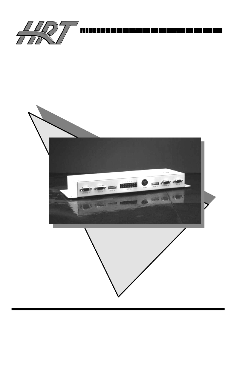
VSM-802B
8 x 2 Video Matrix Switch
With Serial Keypads and Long Cable Compensation
INFORMATION
CUSTOMER
SUPPORT
Order toll-free in the U.S. 800-959-6439
FREE technical support, Call 714-641-6607 or fax 714-641-6698
Mail order: Hall Research Technologies, 1163 Warner Ave., Tustin, CA
Web site: www.hallresearch.com • E-mail: info@ hallresearch.com
92780
UMA1007 Reb B
Page 2

Page 3

8x2 Video Matrix Switch
TRADEMARKS USED IN THIS MANUAL
Hall Research, HRT, and (logo) are trademarks of Hall
Research Technologies, Inc.
Apple and Macintosh are registered trademarks of Apple Computer, Inc.
IBM is a registered trademark of International Business Machines
Corporation.
SGI is a registered trademark of Silicon Graphics, Inc.
Sun and Sun Microsystems are registered trademarks of Sun Microsystems,
Inc. in the United States and other countries.
Any other trademarks mentioned in this manual are acknowledged to be the
property of the trademark owners.
1
Page 4

8x2 Video Matrix Switch
FEDERAL COMMUNICATIONS COMMISSION
AND CANADIAN DEPARTMENT OF COMMUNICATIONS
RADIO FREQUENCY INTERFERENCE STATEMENTS
This equipment generates, uses, and can radiate radio frequency energy
and if not installed and used properly, that is, in strict accordance with
the manufacturer’s instructions, may cause interference to radio
communication. It has been tested and found to comply with the limits
for a Class A computing device in accordance with the specifications in
Subpart B of Part 15 of FCC rules, which are designed to provide
reasonable protection against such interference when the equipment is
operated in a commercial environment. Operation of this equipment in
a residential area is likely to cause interference, in which case the user
at their own expense will be required to take whatever measures may
be necessary to correct the interference.
Changes or modifications not expressly approved by the party
responsible for compliance could void the user’s authority to operate
the equipment.
This digital apparatus does not exceed the Class A limits for radio
noise emission from digital apparatus set out in the Radio Interference
Regulation of the Canadian Department of Communications.
Le présent appareil numérique n’émet pas de bruits radioélectriques
dépassant les limites applicables aux appareils numériques de la classe
A prescrites dans le Règlement sur le brouillage radioélectrique publié
par le ministère des Communications du Canada.
2
Page 5

8x2 Video Matrix Switch
Contents
1. Introduction .......................................................................................4
2. Installation and Configuration ........................................................... 5
3. Operation ........................................................................................... 8
3.1 The Switch’s LEDs...................................................................... 8
3.2 Switching with the Keypads ........................................................ 8
3.3 Blanking the Video Output and Keypad Self-Test ...................... 8
4. Troubleshooting................................................................................. 9
4.1 Problem Solving FAQ ................................................................. 9
4.2 Calling Hall Research Technologies.......................................... 10
4.3 Shipping and Packaging ............................................................10
5. Specifications................................................................................... 11
6. Addendum .......................................................................................12
6.1 Switching with or through a Serial Device................................ 12
6.2 Configuring for Dual-head Display Devices ............................. 13
6.3 Scan Mode ................................................................................. 14
6.4 Blanking the output ................................................................... 15
6.5 Programming the Scan Period for each output .......................... 15
3
Page 6

8x2 Video Matrix Switch
1. Introduction
The Model VSM-802B 8 in x 2 out Video Matrix Switch is an ideal tool
for sharing and/or switching between the output of as many as eight video
sources (such as PCs), in order to display or capture that output at two
video destinations (such as monitors). Once you attach all your devices,
you can hook the Switch to the included keypads for full switching control.
The Switch’s features include:
• With its large bandwidth, it can handle even very high resolutions
and refresh rates, up to 1600 x 1280 pixels at up to 85 Hz.
• It includes two serial keypads, so it’s ready to do manual
switching almost right out of the box (you do have to attach the
keypad to the Switch first).
• Because it has a universal power supply, you can plug it in almost
anywhere if you have the right input cord. (And it’s small and
light enough to take almost anywhere!)
• It’s primarily designed to carry VGA/XGA video, but it can
handle separate horizontal and vertical sync, composite sync, and
sync on green, so with the right kinds of cables or adapters it can
accept all sorts of video from all sorts of devices.
• All of its input and output signals are buffered, so you’ll get the
sharpest possible images.
• It can drive video signals as far as 300 ft. (90 m) end-to-end, so
it’s ideal for use in auditoriums, conference halls, and similar
spaces.
• Its front-panel LEDs show you right away which video inputs are
going to which outputs.
• To top it off, it can be operated by pressing a single keypad
button, so anybody can use it without having to be extensively
trained.
The Switch comes with:
• (2) 10-button keypads
• (2) 6-ft. (1.8-m) DB9 male to DB9 female keypad cables
• Power supply
• This manual
4
Page 7

8x2 Video Matrix Switch
2. Installation and Configuration
To set up your VSM-802B 8 x 2 Video Matrix Switch system, take these
steps:
Making sure that the Switch is powered off, find its input ports. (These are
the HD15 connectors on its front panel labeled “INPUT 1” through
“INPUT 8.”)
Run cabling from these ports to the video-output ports of the PC CPUs or
other devices that will be providing the Switch’s video input. If all of these
input devices are transmitting VGA/SVGA/XGA-type video signals on
HD15 female connectors, you can use standard VGA video extension
cables such as our product CVGX-xx-MM. Keep in mind that the length of
any of these cables plus the length of any of your monitor/output cables
(see step 2) should not be more than 300 ft. (90 m). You’ll configure the
Switch for the length of your cables in step 3.
If any of your input devices transmit some other type of video signal and/or
use some other type of video connector, you might need special cables or
adapters; call HRT Technical Support.
Figure 2-1. The Switch’s rear-panel components.
The Switch’s output ports are the two HD15 female connectors labeled
“OUT A” and “OUT B” on the Switch’s rear panel. If both of your output
devices are standard VGA or multisync monitors with HD15 male
connectors on their video cables, you can plug them directly into these
ports (if they’ll be placed nearby) or run video-extension cables to them
such as our product CVGX-xx-MF (if they’ll be some distance away).
Keep in mind that the length of any of these cables plus the length of any of
your CPU/input cables (see step 1) should not be more than 300 ft. (90 m).
(You’ll configure the Switch for the length of your cables in step 3.)
If either of your output devices is designed to receive a non-VGA video
signal and/or use a different type of video connector, you might need
special cables or adapters; call HRT Technical Support.
5
Page 8

8x2 Video Matrix Switch
1. For each of the two outputs there is an 8-position DIP switch on
the Video Matrix Switch’s rear panel - labeled “GAIN A” for
“OUT A” and “GAIN B” for “OUT B” - that you can use to
control the gain applied to the corresponding
of the eight inputs, calculate the total lengths of the video cables from
the source to each of the two destinations (the devices attached to
OUT A and OUT B). Then set the corresponding switch position (“1”
for input 1 through “8” for input 8 on either GAIN A for OUT A or
GAIN B for OUT B): Move it DOWN if the total length is 100 ft. (30
m) or less, or UP if the total length is over 100 ft. (30 m). (In the UP
setting, extra compensation is added to the signal to make up for the
high-frequency losses typical of longer cabling.)
Run the included 6-ft. (1.8-m) DB9 cable from the two included
2.
input signals. For each
keypads to the DB9 female connectors labeled “KEYPAD A” and
“KEYPAD B” on the Switch’s rear panel. If you have either
monitor placed father than 6-ft. (1.8 m)
use DB9 male to DB9 female extension cable such as CDB9-xx-MF to
run just as far to the keypad, up to the maximum of 300 ft. ( 90 m ) .
3.
Plug the output cord of the Switch’s power supply into the
from the Switch, you can
Switch’s 5-pin DIN female power inlet. Plug one end of the power
supply’s input cord into the transformer’s IEC 320 male inlet; plug
the other end of the input cord into a
Video Matrix Switch system is now fully installed, as shown in Figure
3-2 on the next page.
working AC outlet. Your
4. Now you can turn on all attached devices. The system should
power up in its last state, with each of the Switch’s outputs
displaying its last selected input.
ready for continuous operation. If it doesn’t, check the rear-panel
LEDs to make sure the Switch is ON; check your devices and make
sure they’re ON; and check the cabling and make sure it’s all properly
connected. If everything seems like it should work but the system still
doesn’t, call HRT Technical Support.
6
If it does, the system should be
Page 9

8x2 Video Matrix Switch
Figure 3-2. A fully installed Switch system.
High-Density 15-Pin VGA Connector
PIN Function
1 Red
2 Green
3 Blue
4 Not Used
5 Gnd
6 Red Return (Gnd)
7 Green Return (Gnd)
8 Blue Return (Gnd)
9 Key (Not Used)
10 Gnd
11 Gnd
12 SDA (plug-n-play)
13 Horizontal Sync
14 Vertical Sync
15 SCL (plug-n-play)
7
Page 10

8x2 Video Matrix Switch
3. Operation
3.1 The Switch’s LEDs
The LEDs on the 8 x 2 Video Matrix Switch’s rear panel, shown in Figure
3-1 at the start of Chapter 2, indicate which of the Switch’s outputs are
displaying the video from which inputs, and which outputs have been
blanked and aren’t showing anything (see Section 3.3) .
There are two rows of eight LEDs, labeled “Channel” and “1” through “8.”
The top row shows which input is selected for “OUT A,” while the bottom
row shows which input is selected for “OUT B.” If no LEDs are lit in an
output port’s row, the output has been blanked and the keypad is in test
mode (see Section 3.3)
3.2 Switching with the Keypads
To switch your output port’s monitor or other destination device to display
a given input, press the number of that input on your keypad. For example,
to display the video from a CPU attached to INPUT 8, press the “8” button.
The LED next to that button will light (and will stay lit until a different port
is selected). Buttons 9 and 10 on the keypad have no switching function;
pressing them will have no effect unless you press both at the same time,
which will blank the output and trigger the keypad’s self-test function (see
Section 3.3).
3.3 Blanking the Video Output and Keypad Self-Test
Pressing both the 9 and 10 buttons simultaneously on one of the Switch’s
keypads will blank the video output controlled by that keypad (the monitor
will go dark). It will also cause that keypad to go into self-test mode and
light all of its LEDs. If you see that any of the LEDs don’t light while a
keypad is in this mode, consider contacting HRT to arrange for the keypad
to be repaired or returned. (A dark LED probably just means that the LED
is defective, but there’s a slim chance that something more serious might be
wrong.) To exit test mode and restore video output of the previously
selected channel, press any button (1 through 8).
8
Page 11

8x2 Video Matrix Switch
4. Troubleshooting
4.1 Problem Solving FAQ
1) Fuzzy, blurry, or ghosting image at remote location
If you have a stable but somewhat blurry image (object or character edges
are not sharp), make sure that you have set the unit’s compensation
switches correctly. If you still have a fuzzy image, try reducing the refresh
rate and/or resolution of the PC. You should also be sure to use multicoaxial (double shielded) 75 ohm video extension cables for best results. A
ghosting image is usually an indication of impedance mismatch of the
.
cable
2) Image exhibits steady or rolling horizontal color “hum”
bars
This is usually an indication of improper grounding either at the sending
end, the receiving end, or both. Verify that the AC line is properly wired
and that a protective ground (green) wire is established with NO potential
difference between both the sender and receiver locations.
3) The PC does not recognize a Plug-and-Play monitor
If the PC’s Operating System is setup to detect a plug-and-play monitor
(usually in Display Properties: Advanced Settings), it may have trouble
finding a monitor if it is directly connected to the VSM-802B. If the PC
does not produce an image due to this, disable the plug-and-play monitor
detection in the PC’s operating system.
4) Substituting power supplies
The splitter relies on the AC power adapter that is supplied with it. Do not
substitute any other power supplies.
9
Page 12

8x2 Video Matrix Switch
4.2 Calling Hall Research Technologies
If you determine that your Switch is malfunctioning, do not attempt to
repair the unit. Contact HRT Tech. Support at 714-641-6607.
Before you do, make a record of the history of the problem. We will be
able to provide more efficient and accurate assistance if you have a
complete description, including:
• The nature and duration of the problem
• The components involved in the problem—that is, what type of cable,
makes and models of computers and monitors, etc.
• The results of any testing you’ve already done
4.3 Shipping and Packaging
If you need to transport or ship your splitter:
• Package it carefully. We recommend that you use the original container.
• Before you ship the unit back to HRT for repair or return, contact us to
get a Return Material Authorization (RMA) number.
10
Page 13

8x2 Video Matrix Switch
5. Specifications
Standards: VGA, SVGA, XGA, or XGA-2 video
Interfaces: Video: VGA; Keypads: EIA/TIA RS-232 Serial
Compliance: CE (meets requirements); FCC Part 15 Subpart B Class
A (meets specs),
Supported
Video Types: RGBHV (VGA, SVGA, XGA, or XGA-2), RGBS, or RGsB (“sync
Resolution and
Refresh Rate: Up to 1600 x 1280 non-interlaced at up to 85 Hz
Bandwidth: DC to 265 MHz
Video Level: 0.7 volts peak-to-peak
Video Gain: 1-to-1 (buffered); for distances over 100 ft. (30 m), can be set to
Maximum
Distance: Up to 300 ft. (90 m) of total cable length from any attached CPU or
User Controls: (2) 10-button switching keypads, (1) for each output; (2) Rear-
Indicators: (16) Rear-mounted LEDs, (2) for each video-source port; (10) LEDs
Connectors: Front-mounted: (8) HD15 female for video input;
Max Altitude: 10,000 ft. (3048 m)
Temperature Operating: 0 to 50°C; Storage: –40 to +85°C
Humidity: Up to 95% noncondensing
Enclosure: Steel
MTBF: 300,000 hours (calculated estimate)
Power: From utility-power (mains) outlet, through included detachable output
Size: 1.5"H x 12.1"W x 4.1"D (3.9 x 30.8 x 10.4 cm); mounting ears
Weight: Net: Switch itself: 2.3 lb. (1 kg);
Keypads: 1 lb. (0.5 kg) each; Power supply: 1.3 lb. (0.6 kg);
on green”)
proportionally apply higher gain to higher signal frequencies to
compensate for losses in cable
other input device to any attached monitor or other output device
mounted 8-position DIP switches—(1) for each output port—for
distance compensation
on each keypad
Rear-mounted:
(2) HD15 female for video output
(2) DB9 female for keypad input,
(1) 5-pin DIN female power inlet
cord and external universal power supply:
Input: 100 to 240 VAC at 50 to 60 Hz (autosensing);
Output: +5 VDC at 1 A, +12 VDC at 0.5 A and –12 VDC at 0.5 A;
Consumption: 5 VA (5 watts) maximum
protrude an additional 0.9” (2.2 cm) wide on each side
Shipping: 6.7 lb. (3 kg)
11
Page 14

8x2 Video Matrix Switch
6. Addendum
6.1 Switching with or through a Serial Device
The VSM-802B has two serial ports, one for each of the keypads. One
or both of these ports can be used to control the switch from an
external serial device.
The serial connectors are DB9-F. The following list shows pins used:
Pin 1 (reserved) = Used by keypad (must be left open)
Pin 2 (output) = TX from switch
Pin 3 (input) = RX to switch
Pin 4 (input) = DSR to switch (must be hi for switch to transmit)
Pin 5 (Gnd) = Ground
Pin 6 (output) = DTR from switch (hi indicates ready to receive)
Pin 7 (n/u) = Not Used
Pin 8 (n/u) = Not Used
Pin 9 (reserved) = Used by keypad (must be left open)
Configure port for 9600 Baud, 8 bits, No Parity, 1 Stop bit
Serial Commands:
All commands are made up of ASCII characters followed by carriage
return. x and y are input and output channel numbers respectively.
OyIx Connects y output to x input. If x is 0, then y output is
blanked. The switch will send out an identical string (i.e. OyIx) when
the action is completed
Oy? Returns status of y output in the form of OyIx
You can still have a keypad connected to one of the serial ports and
control the switch simultaneously from an external serial device. If the
output associated with the keypad that is connected is changed via the
external serial device, then the keypad LEDs will reflect the new
selection.
12
Page 15

8x2 Video Matrix Switch
6.2 Configuring for Dual-head Display Devices
If you are using computers with dual-video outputs, you can configure
the VSM-802B to display the video outputs from 4 PC's on to a single
dual-head display.
Connect the left video output of all PCs to inputs #1 through #4, and
the right video outputs to inputs #5 through #8 respectively. Then
connect the "A" output from the switch to your left display device and
the "B" output to the right one.
Connect a PC to either keypad port on the switch using a Straightthrough DB9 M/F cable. Configure a terminal-emulator software, such
as Windows HyperTerminal ™ per settings mentioned in the previous
section.
Type the letter P and the following menu will appear on the screen:
Select Switching Mode
N = Normal
T= Tandem (used for dual-head displays)
Press T on the keyboard; the switch will respond with "Tandem mode
selected". The switch will permanently stay in this mode until you
change it back to normal by performing the same procedure and
selecting N.
Now you can use one of the keypads to select any of the PCs for
display. The keypad must be plugged into "Keypad A" port of the
switch. Buttons 1 through 4 are used to make the desired PC selection.
Buttons 5 through 8 are inactive; however pressing buttons 9 and 10
together will still blank the outputs. When the switch is configured for
tandem mode, you can still use an external serial device (either by itself
or together with a keypad), to control the switch. The command string
is simplified to: Ix (where x is 1 through 4).
13
Page 16

8x2 Video Matrix Switch
6.3 Scan Mode
The VSM-802 now features a Scan Mode whereby each output can
independently cycle through all 8 inputs at a customer specified period.
To enter the Scan Mode for a given output, press keys 9 and 10 at the
same time on the corresponding keypad. To enter the scan mode from a
serial device type: O1S or O2S which forces output 1 or 2 into scan
mode respectively (“ “denotes Enter).
To Exit Scan Mode, just press any key on the keypad. This will cause
the output to switch to selected channel and quit scanning. This can
also be done from a serial device by issuing a valid switch command
such as: O2I5 (see Addendum on page 13 of the manual for details
regarding controlling the switch through a serial device (or Windows®
HyperTerminal™)
When you place an output into scan mode, the Model 802 will
remember and remain in that state even after power off. So if you
disconnect power and reconnect power, it will pick up and start
scanning where it left off. In fact you don’t even need a keypad
plugged in for that output once power is restored!
Scan mode is not available in Tandem or Dual Head Switching mode
(see Addendum on page 14 of the manual for details regarding “DualHead Switching”.
14
Page 17

8x2 Video Matrix Switch
6.4 Blanking the output
Pressing key 9 or key 10 on the keypad will cause the output to be
blanked (all LED’s on the keypad will be lit when the output is
blanked). To come out of blank mode, just press any 1 through 8 keys
on the keypad.
Either output can also be blanked from a serial device by issuing a
switch command with 0 as input such as: O2I0
NOTE: This is the only method
of blanking the output.
Please disregard
paragraph 3.3 on page 8
of the manual
6.5 Programming the Scan Period for each output
You can specify a scan interval for each output from 1 second to 255
seconds. Once you program the scan interval, the model 802 will use
the new period whenever you enter scan mode. The scan mode is set to
10 seconds for both outputs when the unit is shipped from the factory.
To program the scan interval, connect either keypad port of the
VSM802 to a PC (you can use the keypad cable for this purpose).
Configure a terminal emulator (such as HyperTerminal™ which comes
with Windows®) for 9600 baud.
Press the letter “P” on the keyboard. You will see a dialog screen
similar to the following:
P
Select Switching Mode
N = Normal
T =Tandem (used for dual-head displays)
N
Normal mode selected
Scan interval for output 1 (1 to 255 seconds)? 10
Scan interval for output 2 (1 to 255 seconds)? 10
*** END PROGRAM MODE. RESUMING NORMAL OPERATION ***
15
Page 18

8x2 Video Matrix Switch
16
Page 19

Page 20

© Copyright 2005. Hall Research Technologies, Inc... All rights reserved.
1163 Warner Ave., Tustin, CA 92780, Ph: (714)641-6607, Fax -6698
 Loading...