

Page 1
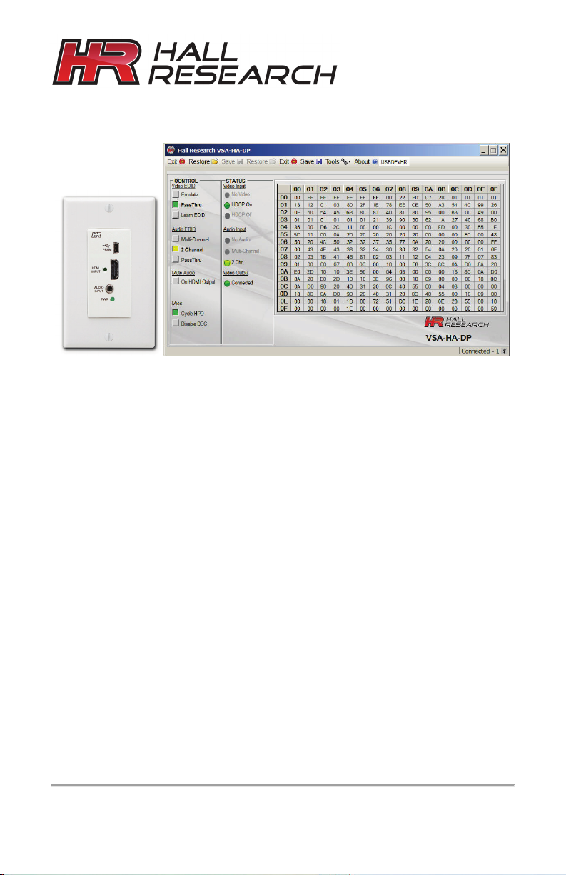
Software GUI
CUSTOMER
SUPPORT
714-641-6607
support@hallresearch.com
UMA1225 GUI Supplement
Rev 1
User’s Manual
EDID & Configuration
Manager Software
for the VSA-HA-DP
INFORMATION
FREE support, Call
Hall Research, 1163 Warner Ave ., Tustin, CA 92780
Web site: www.hallresearch.com
or email
Page 2

Table of Contents
1. WINDOWS™ SOFTWARE INSTALLATION 1
1.1. General 1
1.2. Installation Prerequisites 1
1.3. Software Installation 1
2. USING THE SOFTWARE 2
2.1. General 2
2.2. USB Device Detection 2
2.3. Tool Bar Menu 3
2.4. Device Name 4
2.5. Status Bar 4
2.6. Controls 4
2.7. Status 6
2.8. EDID Data Display 6
2.9. Note about EDID Mixing 7
Trademarks
Hall Research and its logo are trademarks of Hall Research Technologies, Inc. All other
trademarks mentioned in this manual are acknowledged as the property of the trademark
owners.
Page 3

1
© Copyright 2014. Hall Research, Inc.
HDMI Wall Plate with Audio Extraction
1. Windows™ Software Installation
1.1. General
The VSA-HA-DP graphical user interface (GUI) is Windows™ software used to configure
advanced settings of the VSA-HA-DP wall plate. Use of the software requires USB
connection of the PC to the wall plate. For convenience A USB cable is provided with
each wall plate.
The GUI can be used to monitor and configure several wall plates simultaneously. So for
PC's that have multiple USB ports or with the use of external USB hubs, it is possible to
use the same GUI and address each wall plate individually.
1.2. Installation Prerequisites
• A PC with Windows XP™ OS or later
• USB port
• Microsoft™ .NET Framework 2.0 or later (most recent OS including Windows 7 and
8 typically include this and no action is required). If.NET Framework 2.0 or later is
not installed on your PC, the Microsoft™ website has free downloads available.
1.3. Software Installation
• If an earlier version of this particular software was previously installed, UNINSTALL
the program first from either the Add/Remove Programs section of the control panel
or by running the previous installation SETUP.EXE and selecting “remove
application”.
• Install the software by executing the SETUP.EXE program from the installation
source directory
• Accept the default settings, but if you want to specify a particular installation
directory other than the default, you may do so.
• Once the VSA-HA-DP software installation has completed, either
click the desktop icon or navigate the Start Menu to
Start Programs Hall Research VSA-HA-DP Audio Extractor
All rights reserved.
Page 4
VSA-HA-DP Software Guide
2
© Copyright 2014. Hall Research, Inc.
This detection and driver installation only occurs when the VSA-HA-DP is
2. Using the Software
2.1. General
The VSA-HA-DP has no front panel switches, configuration changes are made via the
Software GUI installed on a compatible PC.
The GUI software can be used to manage the EDID routing mode of the device such as
"pass-through" or "emulate", import/export EDID files to/from the device, Set the audio
descriptors in the EDID for (two channel or multi-channel), mute the extracted audio,
remove the audio from the HDMI video output, cycle HPD to the source, and more. The
GUI can also be used to monitor status of several pertinent parameters such as detecting
the input video and audio states and types.
2.2. USB Device Detection
The VSA-HA-DP software automatically configures the USB port after connection to the
wall plate (using standard Windows™ USB drivers) and does not require any special
USB drivers to be installed.
Once connected to a USB port, the Windows™ system will detect and use the
appropriate USB driver. The first time you connect the wall plate to the PC, you may
experience a short delay and a windows notification pop-up message may be shown.
connected to the PC for the first time. Afterwards, reconnected devices
automatically configure themselves with no delay or message.
The software scans the VSA-HA-DP settings continuously in real time, so all
changes are immediately reflected on the screen
If no VSA-HA-DP device is attached to the
system, the on-screen fields are disabled
(grayed out)
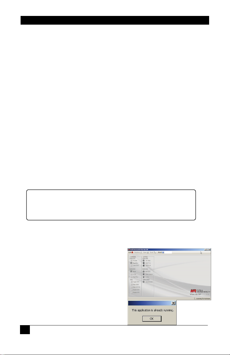
Only one instance of the program can run
at a time. Executing the application more
than once will result in an error message.
All rights reserved.
Page 5

3
© Copyright 2014. Hall Research, Inc.
HDMI Wall Plate with Audio Extraction
Restore device settings from file
Save device settings to a file
Factory Defaults
Exits the application
Displays screen with software versions, website link, legal
2.3. Tool Bar Menu
Used to select previously saved files
Saves the current configuration file to any location on the PC.
Restore the device to factory default settings.
The user must confirm the action.
Import EDID
Import an EDID (256-byte binary or XML file) into the unit.
Export EDID
Save the current EDID as a 256-byte binary file
This file can be edited using third party software and reloaded using
the 'Import EDID' tool selection.
Write EDID (use with caution)
Writes the current 256-byte EDID to the sink device currently
connected to the output . The user must confirm the action.
This command tries to alter the EDID of whatever is connected to
the HDMI output (of the VSA receiver). Most displays such as LCDs
or projectors may have a Read-Only EDID, in which case this
command will not able to alter the EDID in the display. The user
must confirm the action and take all necessary precautions to
prevent loss of data. Hall Research is not responsible for any
damage that may occur from the user attempting to modify the
EDID of the sink device.
Firmware Update
Allows field upgrade of the firmware in the VSA-HA-DP. If your unit
is not upgradable, then this function will be disabled.
disclaimer and copyright information
All rights reserved.
Page 6

VSA-HA-DP Software Guide
4
© Copyright 2014. Hall Research, Inc.
2.4. Device Name
Assigns a descriptive name to the VSA-HA-DP device that is a maximum 8 characters
long. This information is stored in the wall plate. Assigning unique Device Names to each
wall plate can be useful to positively identify each wall plate. This can prove handy if you
are going to upload different configurations for each device, or if you intend to connect
multiple devices simultaneously to a PC and use the software to control several at once.
The FACTORY DEFAULT name is USBDEVHR.
You can change the device name only when just one VSA-HA-DP is connected to the
PC.
2.5. Status Bar
The bottom bar of the screen shows the USB connection status as follows:
This indicates the software has not detected any VSA-HA-
DP devices and is searching the USB ports for devices.
Controls are disabled until a valid VSA-HA-DP device is attached and properly identified
by the software.
Shows the number of VSA-HA-DP devices that are connected to the
PC.
2.6. Controls
VIDEO EDID
The VSA-HA-DP creates an EDID table that the source connected
to the input can read. You can control how the parts of the EDID
table that pertain to video capabilities are constructed. Clicking
these controls selects to either PASS-THRU or EMULATE the
EDID.
PASS-THRU uses the EDID from the Sink device (typically the actual display connected
to the output), while EMULATE uses the internal EDID saved in the VSA-HA-DP.
PASS-THRU is the FACTORY DEFAULT setting.
Learn EDID
Clicking this control will extract the EDID from device connected to
the output connector and save it in the unit.
The user must confirm the action.
All rights reserved.
Page 7

5
© Copyright 2014. Hall Research, Inc.
HDMI Wall Plate with Audio Extraction
AUDIO EDID
Similar to Video EDID, you can control how the parts of the EDID table
that pertain to audio capabilities are constructed. Clicking these controls
selects either PASS-THRU, 2 CHN or MULTI modes
2 CHN – EDID from SINK is set for 2 channel LPCM audio with 2 speakers.
MULTI – EDID from SINK is set for LPCM, DTS and Dolby audio with multiple speakers.
PASS-THRU – EDID from SINK is used
2-Channel is the FACTORY DEFAULT setting. Since the VSA-51 has a stereo 2-channel
audio amplifier, it is best to have the EDID set for two channel regardless of what is
connected downstream.
EDID Routing Modes
Mute Audio
On HDMI output
Clicking this control removes the audio portion from the HDMI video output (on the VSA51 HDMI output connector). You can use this command to make sure no audio comes
out of the display's built-in speakers.
FACTORY DEFAULT is not muted.
Misc
Cycle HPD
Clicking this control sends causes a 0.5 second pulse on the
Hot Plug Detect signal that is sent to the video source. So
basically the source will see an unplug and a re-plug. It has the
same effect of unplugging the HDMI input cable and plugging it back in. This forces the
source to re-initialize its HDMI video output connection (read EDID, and implement
HDCP if required) This indicator is ‘filled green’ when the source is connected.
All rights reserved.
Page 8

VSA-HA-DP Software Guide
6
© Copyright 2014. Hall Research, Inc.
Disable DDC
Enabling this control will turn off the DDC communication with the SOURCE device. The
SOURCE will receive no response from any HDCP or EDID requests. This effectively
disables the SOURCE from displaying HDCP content and most PC's will not output any
video if they can't read the EDID.
FACTORY DEFAULT is not enabled (HDCP and EDID are enabled).
2.7. Status
Video Input
No Video
Indicates the system is not receiving an INPUT video signal.
HDCP On
Indicates video received has HDCP Encryption enabled.
HDCP Off
Indicates video received has HDCP Encryption disabled.
Audio Input
No Audio
Indicates no audio received (DVI mode)
Multi-Channel
Indicates HDMI audio received is not LPCM format.
2 Chn
Indicates HDMI audio received is LPCM format.
Video Output
Connected or Disconnected
Indicates the state of the device connected to the VSA-HA-DP OUTPUT.
2.8. EDID Data Display
The data shown in the EDID table is continuously and updated on the screen. Also the
software ensures that the checksums for each block is valid.
All rights reserved.
Page 9

7
© Copyright 2014. Hall Research, Inc.
HDMI Wall Plate with Audio Extraction
When an invalid checksum is detected, that byte (at the end of 128 bytes) is highlighted
in RED. This helps identify invalid EDID checksum values that can cause connectivity
problems.
If you perform an action that affects the EDID, it is possible for the checksum to
momentarily show ‘RED’ until the complete EDID has been updated on the screen.
You cannot “LEARN” an EDID that has an invalid checksum!
The GUI interface software WILL let you IMPORT EDID’s that contain invalid checksum
data for testing purposes.
2.9. Note about EDID Mixing
At power up, the default EDID stored within the device is loaded. This could be either the
factory default or a ‘Learned’ EDID.
If a functioning and valid SINK device is connected to the VSA-HA-DP ‘Output’ connector
AND the VIDEO mode is set to PASS-THRU, the EDID from the SINK will be read and
loaded into memory.
If the SINK EDID read is a simple 128 byte EDID (like a VGA monitor), a CEA-861
extension block (2nd 128 bytes) will be added to the EDID with a default native resolution
of 480p and with LPCM 2 channel audio.
If the SINK is disconnected from the VSA-HA-DP connector, the internally saved EDID
will be presented to the SOURCE mixed according to the AUDIO settings. Each time the
VIDEO or AUDIO EDID GUI controls are pressed, the EDID presented to the SOURCE is
would be as shown in the following table:
All rights reserved.
Page 10

VSA-HA-DP Software Guide
8
© Copyright 2014. Hall Research, Inc.
EM
PASS
NOT POSSIBLE
VIDEO MODE AUDIO MODE EDID EFFECT
PASS PASS SINK EDID PASSED WITH CEC ADDRESS MODIFICATION
PASS 2CHN SINK EDID PASSED WITH 2CHN AUDIO AND CEC ADDRESS
PASS MULTI SINK EDID PASSED WITH 2CHN, DTS AND DOLBY AUDIO AND
EM 2CHN INTERNAL EDID PASSED WITH 2CHN AUDIO AND CEC
EM MULTI INTERNAL EDID PASSED WITH 2CHN, DTS AND DOLBY AUDIO
MODIFICATION
CEC ADDRESS MODIFICATION
ADDRESS MODIFICATION
AND CEC ADDRESS MODIFICATION
CEC Address modification consists of taking the SINK or INTERNAL EDID and modifying
the address to insert the VSA-HA-DP CEC Physical address into the CEC chain. (The
VSA-HA-DP device does not understand any CEC commands).
For example: SINK EDID has CEC address of 0.0.0.0
EDID given to source will show the VSA-HA-DP as CEC address 1.0.0.0 and the display
still with its original CEC address of 0.0.0.0
All rights reserved.
Page 11

9
© Copyright 2014. Hall Research, Inc.
HDMI Wall Plate with Audio Extraction
All rights reserved.
Page 12

© Copyright 2014. Hall Research, Inc.
All rights reserved.
 Loading...