

Page 1
SUPPORT &
ORDERING
INFORMATION
Model VSA-31-IP
IP to Dual RS232 Controller
For use with Hall Research Switch-Cat® products
For technical support, Call 714-641-6607 or fax 714-641-6698
Order by phone: toll-free in the U.S. 800-959-6439
Web site: www.hallresearch.com
Hall Research 1163 Warner Ave. Tustin, CA 92780
UMA 1166 Rev. B
Page 2

Page 3
Model VSA-31-IP
TRADEMARKS USED IN THIS MANUAL
Hall Research, HR, and the
Any other trademarks mentioned in this manual are acknowledged to be the property of the
trademark owners.
logo are trademarks of Hall Research Inc.
FEDERAL COMMUNICATIONS COMMISSION
RADIO FREQUENCY INTERFERENCE STATEMENT
This equipment generates, uses, and can radiate radio frequency energy and if not
installed and used properly, that is, in strict accordance with the manufacturer’s
instructions, may cause interference to radio communication. It has been designed to
comply with the limits for a Class A computing device in accordance with the
specifications in Subpart B of Part 15 of FCC rules, which are designed to provide
reasonable protection against such interference when the equipment is operated in a
commercial environment. Operation of this equipment in a residential area is likely to
cause interference, in which case the user at there own expense will be required to take
whatever measures may be necessary to correct the interference.
Changes or modifications not expressly approved by the party responsible for
compliance could void the user’s authority to operate the equipment.
This digital apparatus does not exceed the Class A limits for radio noise emission from
digital apparatus set out in the Radio Interference Regulation of the Canadian
Department of Communications.
1
Page 4

IP DUAL PORT CONTROLLER
Contents
1. Introduction......................................................................................................... 3
1.1 General....................................................................................................... 3
1.2 Features...................................................................................................... 4
2. Installation .......................................................................................................... 5
2.1 Connecting the Unit................................................................................... 5
2.2 Connector Pin Out ..................................................................................... 6
2.3 Indicators ................................................................................................... 7
3. Configuration ...................................................................................................... 7
3.1 Ethernet Configuration .............................................................................. 7
3.2 Serial Configuration................................................................................... 8
4. Operation ........................................................................................................... 9
4.1 RS-232-A to/from RS-232-B with LAN Monitoring ................................ 9
4.2 RS-232-A to/from LAN........................................................................... 10
4.3 RS-232-B to/from LAN........................................................................... 10
4.4 DS Manager ............................................................................................. 12
4.4 Software GUI........................................................................................... 13
4.5 Access via Port 23 and Port 1001 ............................................................ 15
5. Troubleshooting ................................................................................................ 18
5.1 Contacting Hall Research ........................................................................ 18
5.2 Shipping and Packaging .......................................................................... 18
6. Specifications.................................................................................................... 19
Hall Research Inc.
Home of the Mini-Cat®
2
Page 5
Model VSA-31-IP
1. Introduction
1.1 General
The model VSA-31-IP is a member of Hall Research powerful RS232 product line. The
unit allows the user a flexible interface to perform the following functions:
• Monitor the RS232 communication between 2 serial devices from a remote
LAN connection
• Independently send and receive RS232 signals to separate serial devices from
a remote LAN connection at any speed
• Timeout feature - Default back to a standard communication path after 3
minutes to ensure that the 2 serial devices are always connected
• Detect connection to RS232-A port from a remote LAN connection without
disturbing the communication between RS232-A and RS232-B
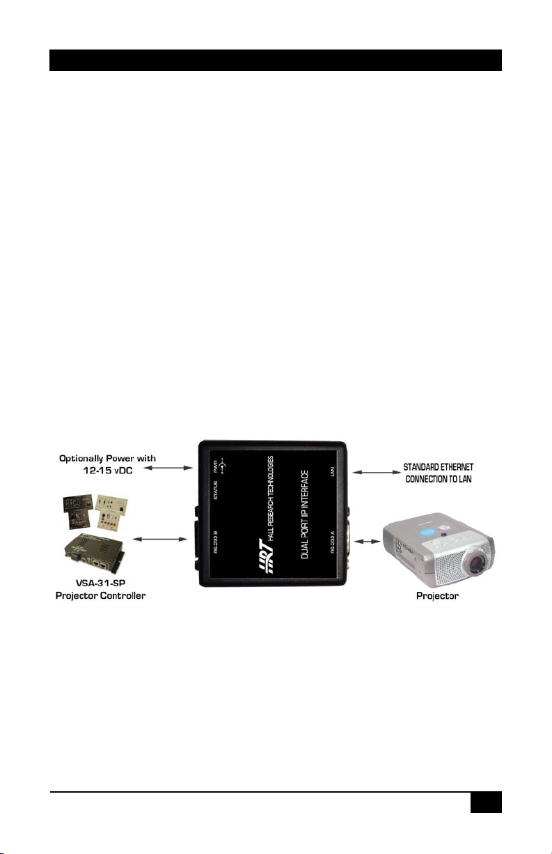
When the VSA-31-IP is used to add IP capability to a classroom equipped with Hall
Research Switch-Cat® system, it is inserted in the RS-232 path between the VSA-31
Receiver and the Projector. It draws power from the VSA-31 Receiver and includes the
cable for connection to the VSA-31 Receiver.
Figure 1 – Typical Setup
3
Page 6
IP DUAL PORT CONTROLLER
1.2 Features
Dual RS232 Ports
Supports all Serial baud rates, parity and data bits
10/100 Base-T Ethernet ready
User selectable IP Address, MAC, Gateway and Net Mask
2 LED’s for indication of Power, IP-to Serial Routing, and/or Ethernet Status
Detect serial device connected to RS232-A port without disturbing the serial
communication. (Theft Detection or Power Loss)
Can be inserted in-line to silently monitor RS232 communication between
RS232-A RS232-B ports from a remote LAN connection
Communication path is selectable between
RS232-A RS232-B , IP RS232-A or IP RS232-B
Can be powered from the RS232 (B side) port or from optional external Power
Supply
Includes F/F DB9 null modem cable for connection to the VSA-31 Receiver
Compact Size
Made in USA
4
Page 7
Model VSA-31-IP
2. Installation
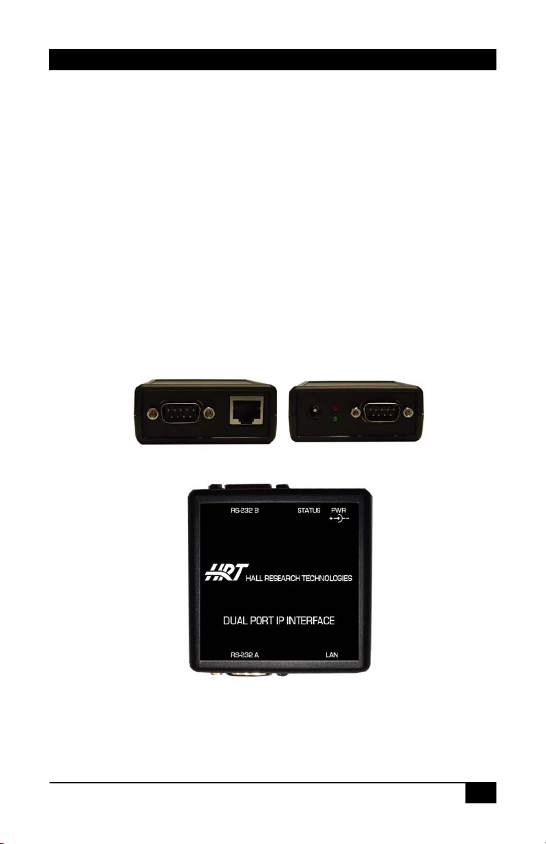
2.1 Connecting the Unit
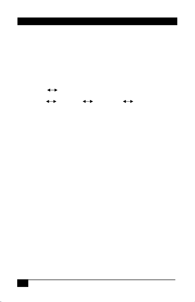
Refer to Figure 1 and 2 below for connector identification.
Connect the “RS232-A” and the “RS232-B” ports to the serial devices using
appropriate cables (for example, since the VSA-31 Receiver has a DB9 Male
connector, a Female/Female RS-232 NULL Modem cable should be used).
Connect the “LAN” port to a network Ethernet connection using standard CATx
cables (not supplied with unit)
Connect the “PWR” jack to the power supply (optional) or connect the unit to a Hall
Research compatible device capable of powering the unit via the RS232-B port
using the supplied RS232 Null Modem cable.
RS-232-A LAN
Figure 2 – End Panel Views
PWR
STATUS
10/100
RS-232-B
Figure 3 – Top View
5
Page 8
IP DUAL PORT CONTROLLER
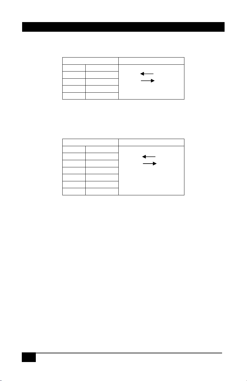
2.2 Connector Pin Out
RS-232-A Connector: This 9-pin D-sub connector is normally used to connect to the
“Controlled” device, such as a Projector (though any serial device is acceptable).
RS-232-A PORT Direction To/From Unit
PIN Definition
2 RxD
3 TxD
5 GND
7 RTS Pulled High
RS-232-B Connector: This 9-pin D-sub connector is normally used to connect to the
“Controller” device, such as a VSA-31 Receiver (though any serial device is acceptable).
This connector can also be used to power the VSA-31-IP unit. The power source must
be capable of 12-15 vDC @ 250 mADC minimum.
RS-232-B PORT Direction To/From Unit
PIN Definition
2 RxD
3 TxD
4 DTR Pulled High
5 GND
6 PWR IN 12-15 vDC 250 mADC
7 RTS Pulled High
PWR connector: This is a standard 2.5mm plug connection. The unit’s power supply is
12-15 volts DC with a minimum rating of 250 mADC. Upon application of power from
the 2.5mm PWR connector or by the RS-232-B Pin 6, the 10/100 and Status LED’s will
either blink or become illuminated solid. Refer to Section 2.2 for a description of the LED
functions.
LAN connector: This is a standard RJ-45 Ethernet connection capable of be connected
to any 10/100 BaseT network.
6
Page 9

Model VSA-31-IP
2.3 Indicators
The VSA-31-IP has one RED and one GREEN LED. The function of each LED is
changed depending on the mode of operation, Ethernet connection status and
power status.
10/100 (GREEN) Status (RED) RS232 Path Time Limit
No Power Applied
to Unit
Power Applied,
but no Ethernet
connection
Power Applied,
Ethernet
Connection
achieved
Connection:
RS-232-A to LAN
Connection:
RS-232-B to LAN
OFF OFF NONE NONE
Slow Blink Slow Blink RS232-A to
ON (LAN 10/100
Status)
ON (LAN 10/100
Status)
Fast Blink ON (LAN 10/100
ON (LAN Status) RS232-A to
Fast Blink RS232-A to LAN 3 Minutes (if IP
Status)
RS232-B
RS232-B
RS232-B to LAN 3 Minutes (if IP
None
None
fails to restore
A<>B connection)
fails to restore
A<>B connection)
3. Configuration
3.1 Ethernet Configuration
The Ethernet configuration of the VSA-31-IP must be correctly setup in order for the
end user to be able to communicate with the device across the network. Incorrect
configuration will result in the user not being able to communicate with the device.
The VSA-31-IP comes from the factory with a default configuration setup in the unit
as follows:
IP Address: ........................................................................192.168.123.199
Gateway:................................................................................192.168.123.1
Net Mask:...............................................................................255.255.255.0
If the configuration of the end users LAN is compatible with these default settings,
then the user is not required to make changes to the Ethernet Configuration.
If the configuration is not compatible, use the Hall Research DS Manager to change
the unit’s configuration.
Set the IP Address to any STATIC unused address available on the end-users
network. This IP Address of the VSA-31-IP must be in the same node as any
computer attempting to access the device. If the computer attempting to access the
device is on another network node, then the end-user is responsible for configuring
any network routers or switches necessary to allow access to the devices IP
7
Page 10

IP DUAL PORT CONTROLLER
Address on Ports 23 and 1001. Contact your network IT administrator for
assistance with these settings.
Set the Gateway Address to the required IP Address of the end-users Gateway. If
the end-user will always access the VSA-31-IP device from a computer connected
on the same network node, then the Gateway Address may be left at its default
value. Contact your network IT administrator for assistance with these settings.
Set the Net Mask to the required values compatible with the end-users network. If
the end-user will always access the VSA-31-IP device from a computer connected
on the same network node, then the Net Mask may be left at its default value.
Contact your network IT administrator for assistance with these settings.
3.2 Serial Configuration
At Power-Up, the VSA-31-IP makes a default connection from the RS-232-A port to
the RS-232-B port.
In this mode, all communication between the RS-232-A and RS-232-B port is
transmitted to the LAN connection on the VSA-31-IP units IP address, Port 1001.
No information transmitted from the LAN connection will be sent to the RS-232-A or
RS-232-B ports.
All communication through the LAN Port must occur at whatever baud rate, parity,
data bits and stop bit used by the RS-232-A and RS-232-B ports.
In order to communicate with the VSA-31-IP via the LAN, the unit must be
configured to operate at the same baud rate, parity, data bits and stop bit settings
being used by the devices connected to the RS-232-A and RS-232-B ports.
If you will not be communicating via the LAN to the VSA-31-IP unit, then the enduser does not need to change anything.
The VSA-31-IP serial parameters may be altered by the following methods:
Use the Hall Research VSA-31-IP Software GUI
Use the Hall Research DS Manager to change the related parameters
Use a HyperTerminal TCP connection to the IP Address on the VSA-31-IP
using a Telnet connection to Port 23 using the appropriate commands.
The VSA-31-IP also has the ability to communicate bi-directionally from the LAN
port to the RS-232-A port or the LAN port to the RS-232-B port.
Any information transmitted to the unused RS-232 port is discarded.
To change the direction of the communication, the end-user is required to control 3
I/O lines via the VSA-31-IP IP Address Port 23.
In this mode, the end-user has a time limit of 3 minutes from the time the connection
is changed from the default RS-232-A to/from RS-232-B path. The time limit starts
whenever the VSA-31-IP units P1 line is set from “0” to “1”. If more than 3 minutes
is required to communicate on the LAN port, the end-user is responsible for toggling
the VSA-31-IP unit P1 line from “0” to “1” (if using Hall Research VSA-31-IP
Software GUI, this is done automatically) .
8
Page 11

Model VSA-31-IP
4. Operation
4.1 RS-232-A to/from RS-232-B with LAN Monitoring
At power-up, the VSA-31-IP unit defaults to a RS232-A to/from RS232-B path.
Communication occurs without user intervention at whatever baud rate, parity, data
bits and stop bits used by the devices connected to the RS-232-A and RS-232-B
ports.
All communication along the RS-232-A and RS-232-B path is echoed to the IP
Address of the VSA-31-IP on Port 1001. This communication can be monitored
using a HyperTerminal TCP connection.
The baud rate, parity, data bits and stop bits of the VSA-31-IP unit must match the
settings of the devices communicating on the RS-232-A and RS-232-B ports.
The VSA-31-IP unit Serial Parameters may be altered by the following methods:
Use the Hall Research VSA-31-IP Software GUI
Use the Hall Research DS Manager to change the related parameters
Use a HyperTerminal TCP connection to the IP Address on the VSA-31-IP
using a Telnet connection to Port 23 using the appropriate commands.
9
Page 12

IP DUAL PORT CONTROLLER
4.2 RS-232-A to/from LAN
In order to command the VSA-31-IP unit to communicate on the RS-232-A to LAN
path, the VSA-31-IP unit must be told to create that connection path by configuring
the units P0 and P1 lines (if using Hall Research VSA-31-IP Software GUI, this is
done automatically).
Set “P0” to Low (0)
Set “P1” to High (1)
Set “P1” to Low (0)
Set “P1” to High (1)
The Status (RED) led will flash quickly and the 10/100 (GREEN) led will be ON.
The LAN and RS-232-A port will now communicate at whatever serial parameter
settings have been configured. Obviously, the device connected to the RS-232-A
port and the LAN must have the same settings for the communication to be
meaningful.
There is a 3 minute time limitation in this state before the VSA-31-IP unit will change
automatically to the default (RS-232-A to/from RS-232-B) path.
4.3 RS-232-B to/from LAN
In order to command the VSA-31-IP unit to communicate on the RS-232-B to LAN
path, the VSA-31-IP unit must be told to create that connection path by configuring
the units P0 and P1 lines (if using Hall Research VSA-31-IP Software GUI, this is
done automatically).
Set “P0” to Low (1)
Set “P1” to High (1)
Set “P1” to Low (0)
Set “P1” to High (1)
The 10/100 (GREEN) led will flash quickly and the Status (RED) led will be ON.
The LAN and RS-232-B port will now communicate at whatever serial parameter
settings have been configured. Obviously, the device connected to the RS-232-B
port and the LAN must have the same settings for the communication to be
meaningful.
There is a 3 minute time limitation in this state before the VSA-31-IP unit will change
automatically to the default (RS-232-A to/from RS-232-B) path.
10
Page 13

The following table shows the different configurations possible using the VSA31-IP unit’s P0, P1 and P8 lines.
RS232
Connection
At POWER
UP
NO IP
Connectio
n
AT
POWER
UP
A e─fB
IP ‘Sniffs’
A e─fB
IP ‘Sniffs’
A e─fIP Red 10/100
B e─fIP
Green
STATUS
Led
Flashing
@ 3 Hz
10/100 &
Status LED’s
Both Red &
Green
LED’s Flash
@ ~1.3 Hz
Both Red &
Green
LED’s
Reflect
Ethernet
Connection
Status
Both Red &
Green
LED’s
Reflect
Ethernet
Connection
Status
Led
Flashing @
3 Hz Green
Status Led
reflects
Ethernet
Connection
Status
Green
Status Led
Flashing @
3 Hz Red
10/100
reflects
Ethernet
Connection
Status
Model VSA-31-IP
PO P1 P6 P8 Notes
A e─fB
X (Don’t
Care)
DEFAUL
T = 1
X (Don’t
Care)
0 1 Low =
1 1 Low =
X (Don’t
Care)
DEFAUL
T = 1
0 Low =
Low =
RS232 A
Active
High =
RS232 A
In-Active
RS232 A
Active
High =
RS232 A
In-Active
RS232 A
Active
High =
RS232 A
In-Active
RS232 A
Active
High =
RS232 A
In-Active
High =
Use JP1
Low =
Ignore
JP1
High =
Use JP1
Low =
Ignore
JP1
High =
Use JP1
Low =
Ignore
JP1
Set LOW
to disable
3 Minute
Time
Limitation
High =
Use JP1
Low =
Ignore
JP1
Set LOW
to disable
3 Minute
Time
Limitation
communication possible,
but none thru IP. No
time limitation
A e─fB
communication possible,
IP (Port 1001) sees the
communication at
whatever baud rate is
being used by A & B. No
time limitation
A e─fB
communication possible,
IP (Port 1001) sees the
communication at
whatever baud rate is
being used by A & B. No
time limitation
A e─fIP
communication possible,
IP (Port 1001) sees the
communication at
whatever baud rate is
being used by A. 3
Minute time limitation for
each P1 Rising Edge
Transition
B e─fIP
communication possible,
IP (Port 1001) sees the
communication at
whatever baud rate is
being used by B. 3
Minute time limitation for
each P1 Rising Edge
Transition
11
Page 14

IP DUAL PORT CONTROLLER
4.4 DS Manager
When the Hall Research DS Manager is run, a window is shown that displays all of the IP
equipped devices reachable in the same network node.
If no devices are displayed, you must click the “REFRESH” button to update the window.
If you still see no IP equipped devices, check with your IT administrator to ensure that all
the proper network routings are in place.
The user must select the desired device and click the “SETTINGS” button to obtain
access to that device’s configurable parameters.
To change a parameter, click on the field next to the parameter’s name and enter the
appropriate information.
Click the OK button when finished and the information will be uploaded into the VSA-31IP module. There will be a short time delay while the VSA-31-IP module reboots.
12
Page 15

Model VSA-31-IP
4.4 Software GUI
The VSA-31-IP Software GUI allows the end-user to monitor and control multiple VSA31-IP modules from one computer via a LAN connection.
The VSA-31-IP Software GUI has separate documentation describing its usage and
operation. Refer to http://www.hallresearch.com/page/Products/VSA-31-IP
documentation pertaining to the VSA-31-IP and the Software GUI.
The computer must be able to access the VSA-31-IP modules IP Address from the
computer location the Software GUI is being executed on. If you can not ping the VSA31-IP modules IP Address then you will not be able to control or monitor the modules
status.
The software GUI contains a list of the VSA-31-IP MAC and IP Addresses so that it can
communicate with each module and ultimately control the devices connected to the RS232-A and RS-232-B ports.
Use the Hall Research DS Manager to configure each module that will be used in the
system and make note of Each Units
address MUST BE UNIQUE for proper LAN communication. The information for each
VSA-31-IP module must be entered into the Software GUI so that device can be located
via the network LAN.
The commands that will be sent to the RS232 devices are unique and must be entered
correctly in order to get a specific response from that device. The following commands
are required and must be supported by the devices connected to the VSA-31-IP module.
IP address and MAC address. Each MAC and IP
for the latest
Lamp Hours
o This command requests the RS232-A device to return the current
number of hours the devices LAMP has been illuminated
Power Status
o This command requests the RS232-A device to return the status of
whether it is turned on or off
13
Page 16

g
IP DUAL PORT CONTROLLER
The figures below show screens that could be only similar to
the actual Software GUI screens. Refer to
http://www.hallresearch.com/page/Products/VSA-31-SP
latest updates concerning the VSA-31-IP Software GUI
for the
List of
Buildin
List of
Buildings
Enter the IP and
corresponding Address
for each Module
s
User can RIGHT CLICK on
Refreshes
list
List of
Devices
Shows the status of
each device and ALL
ROOMS (not
buildings)
PWR is the
Projectors Response
to a Power Status
Query.
CONNECTION is the
RS232-A Port
Connection Status
via P6 of VSA-31-IP
Lamp Hours is the
Projectors Response
to a Lamp Hours
Query.
Enter descriptive
information about
the module and
what it is
connected to
Enter the
commands to send
from the LAN to
the RS232 devices
connected to the
14
Page 17

Model VSA-31-IP
4.5 Access via Port 23 and Port 1001
A HyperTerminal TCP/IP connection can be used to access either PORT 23 or 1001.
Port 1001 is used for the RS232 communication through the VSA-31-IP. All
communication occurs at the baud rate of the devices attached to the RS-232A and RS-232-B ports. The LAN connection Baud Rate must match the speed
being used by the RS232 ports for meaningful communication to occur.
Port 23 is used to change specific parameters in the VSA-31-IP module such
as its IP Address, Gateway Address, Baud Rate…etc.
To run a HyperTerminal window, open the application and set it up for TCP/IP connection
on PORT 23 along with the VSA-31-IP IP address as the host address.
Commands to PORT 23 have the following format and replies:
STX Command/Reply CR
• STX character (ASCII code 0x02 or CTRL-B from the keyboard)
The unit will respond with the following codes indicating the status of the command
requested. Anything other than ‘Accepted’ indicates a problem with that
command/connection to the VSA-31-IP Module:
<^B>A means Accepted
<^B>C means Error
<^B>R means Rejected
<^B>D means Denied
<^B>F means Failed
<^B>S means Bad Sequence
In the following table, the following notations are used:
<^B> denotes the STX Character, 1 Byte of 0x02
<CR> denotes the CR Character, 1 Byte of 0x0D
<^B>L<CR> Log Into Module <^B>A<CR>
<^B>O<CR> Log Out of
<^B>E<CR> Reboot Module None IP Connection
<^B>GFE<CR> Get Modules
Command Purpose Reply Notes
Module
MAC Address
<^B>A<CR>
<^B> xxx.xxx.xxx.xxx.xxx.xxx<CR>
Where xxx.xxx.xxx.xxx.xxx.xxx
represents the MAC Address
to module will
be lost
15
Page 18

IP DUAL PORT CONTROLLER
<^B>SFExxx.xxx.xxx.xxx.xxx.xxx<CR>
Where xxx.xxx.xxx.xxx.xxx.xxx represents the
MAC Address
<^B>GIP<CR> Get Modules IP
<^B>SIPaaa.bbb.ccc.ddd<CR>
Where aaa.bbb.ccc.ddd represents the IP Address
<^B>GPN<CR> Get Modules Port
<^B>SPNaaaaa<CR>
Where aaaaa represents the Port Number
<^B>GGI<CR> Get Modules
<^B>SGIaaa.bbb.ccc.ddd<CR>
Where aaa.bbb.ccc.ddd represents the Gateway
Address
<^B>GNM<CR> Get Modules
<^B>SNMaaa.bbb.ccc.ddd<CR>
Where aaa.bbb.ccc.ddd represents the SubNet
Mask
<^B>GBR<CR> Get Modules
<^B>SBRaa<CR>
Where aa represents the Baud Rate as follows:
0 = 1200 5 = 38400 10 = 600
1 = 2400 6 = 57600 11 = 28800
2 = 4800 7 = 115200
3 = 9600 8 = 150
4 = 19200 9 = 300
<^B>GPR<CR> Get Modules
<^B>SPRaa<CR>
Where aa represents the Parity as follows:
0 = Off or None
1 = Even
2 = Odd
3 = Mark
4 = Space
16
Command Purpose Reply Notes
Set Modules MAC
Address
Address
Set Modules IP
Address
Number
Set Modules Port
Number
Gateway Address
Set Modules
Gateway Address
SubNet Mask
Set Modules
SubNet Mask
Baud Rate
Set Modules
Baud Rate
Parity
Set Modules
Parity
<^B>A<CR>
<^B>Aaaa.bbb.ccc.ddd<CR>
Where aaa.bbb.ccc.ddd represents
the IP Address
<^B>A<CR>
<^B>Aaaaaa <CR>
Where aaaaa represents the Port
Number from 0 to 65534
<^B>A<CR>
<^B>Aaaa.bbb.ccc.ddd<CR>
Where aaa.bbb.ccc.ddd represents
the Gateway Address
<^B>A<CR>
<^B>Aaaa.bbb.ccc.ddd<CR>
Where aaa.bbb.ccc.ddd represents
the SubNet Mask
<^B>A<CR>
<^B>Aaa <CR>
Where aa represents the Baud Rate
as follows:
0 = 1200 5 = 38400 10 = 600
1 = 2400 6 = 57600 11 = 28800
2 = 4800 7 = 115200
3 = 9600 8 = 150
4 = 19200 9 = 300
<^B>A<CR>
<^B>Aaa <CR>
Where aa represents the Parity as
follows:
0 = Off or None
1 = Even
2 = Odd
3 = Mark
4 = Space
<^B>A<CR>
1st Digit must
be EVEN.
Must
REBOOT for
changes to
take effect
It is
recommende
d that the
MAC address
not be
changed
Must
REBOOT for
changes to
take effect
Defaults to
1001
Must
REBOOT for
changes to
take effect
Must
REBOOT for
changes to
take effect
Must
REBOOT for
changes to
take effect
Must
REBOOT or
LOG OUT for
changes to
take effect
Must
REBOOT or
LOG OUT for
changes to
take effect
Page 19

<^B>GBB<CR> Get Modules
<^B>SBBaa<CR>
Where aa represents the Data Bits per Byte as
follows:
0 = 7
1 = 8
Command Purpose Reply Notes
Serial Data Bits
Per Byte
Set Modules
Serial Data Bits
Per Byte
<^B>Aaa <CR>
Where aa represents the Data Bits per
Byte as follows:
0 = 7
1 = 8
<^B>A<CR>
Note on IP Settings via port 23
If you are unable to access the unit’s
port 23 from your PC using the IP
Modules default or last known IP
address, it could be that the IP
address of the IP Module is not
compatible on your LAN. One way
around this is to connect your PC
directly to the IP Modules RJ45 port
using a cross over cable, or use a
switch or router not connected to
anything else but your PC and the IP
Module, and then configure your PC
for a static IP address compatible
with the current address of the IP
Module. If the IP Module has the
factory default of 192.168.123.199, a PC address of
192.168.123.nnn may be entered where nnn is any number except
199.
Model VSA-31-IP
Must
REBOOT or
LOG OUT for
changes to
take effect
17
Page 20

IP DUAL PORT CONTROLLER
5. Troubleshooting
There are no field serviceable parts or circuits in the device. If you think that the device is
malfunctioning, please verify the following:
The LED’s are lit indicating that power is applied to the unit via the RS232-B
port or from an external power supply.
You are using the correct RS232 cables for the devices that are attached to the
RS-232-A and RS-232-B ports. Using the wrong cable (e.g. … Using a straightthru cable when a null modem cable is required) will prevent the RS232
communication from working.
When attempting to utilize the LAN connection, verify that you can get a
response when you ping the devices IP address. If you are unable to get a
response from the VSA-31-IP via a ping, ensure that the computer you’re using
is on the same network node as the VSA-31-IP. (For example, your computer
IP address is 192.168.123.
192.168.123.150). Contact your IT Administrator for assistance.
104 and the VSA-31-IP IP address is
5.1 Contacting Hall Research
If you determine that your VSA-31-IP is malfunctioning, do not attempt to repair the unit.
There are no user serviceable parts inside the unit. Opening the unit will void the
warranty.
Contact the Hall Research Technical Support department at 714-641-6607 to obtain an
RMA (Return Authorization) number.
Before you do, make a record of the history of the problem. We will be able to provide
more efficient and accurate assistance if you have a complete description.
5.2 Shipping and Packaging
If you need to transport or ship your device:
• Package it carefully. We recommend that you use the original container if possible.
• Before you ship the units back to Hall Research for repair or return, contact us to
get a Return Authorization (RMA) number.
18
Page 21

6. Specifications
Dimensions: 2.6 inch (Wide) x 2.6 inch (Deep) x 1.10 inch (High)
Weight: 0.26 Pounds (120 g)
Input Power: 12-15 vDC, 200 mADC max via RS232 Port “B” or
2.5 mm PWR connector
Enclosure: Black Plastic ABS-94VO, UL File#56070
Temperature: Operating: 32 to 122 Deg F (0 to 50 Deg C);
Storage: -40 to +185 Deg F (-40 to +85 Deg C)
Model VSA-31-IP
19
Page 22

IP DUAL PORT CONTROLLER
20
Page 23

Page 24

© Copyright 2009. Hall Research Inc.
All rights reserved.
1163 Warner Ave., Tustin, CA 92780
Ph: (714)641-6607, Fax: (714)641-6698
 Loading...