

Page 1
H
R
aallll
H
eesseeaarrcchh
R
T
eecchhnnoollooggiieess,, IInncc..
T
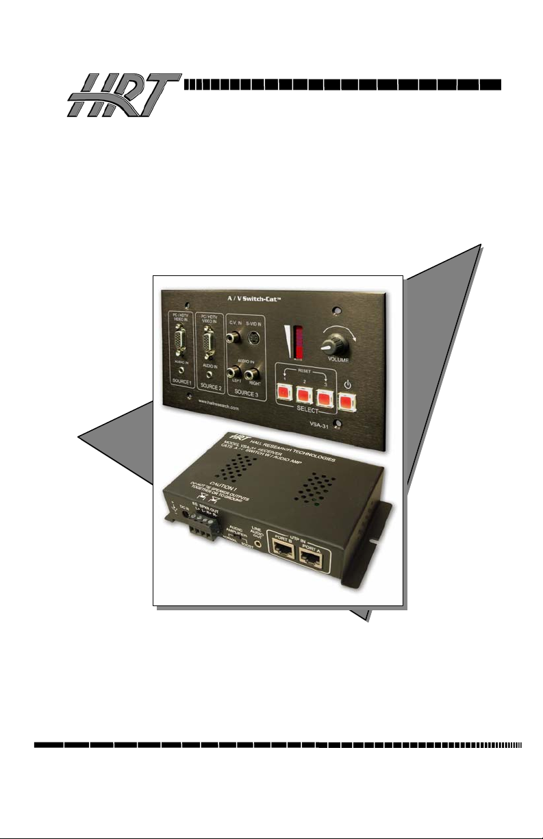
Model VSA-31
A / V Switch-Cat
All-in-One A/V Distribution System
Switching, UTP Transmission, Serial Control, and Audio Amplification
TM
UMA1114 Rev B
© Copyright 2007. Hall Research Technologies, Inc. All rights reserved.
1163 Warner Ave Tustin, CA 92780, Ph: (714)641-6607, Fax -6698
Page 2

Model VSA-31
Trademarks Used In this Manual
Hall Research and (logo) are trademarks of Hall Research Technologies, Inc.
Any other trademarks mentioned are the property of the trademark owners.
FCC and European Union Declaration of Conformity
This equipment generates, uses and radiates radio frequency energy and,
if not installed and used in accordance with the instructions, may cause
harmful interference to radio communications. It complies with the limits
for a Class A computing device, pursuant to Part 15 of the FCC rules.
This product complies with the requirements of the European EMC
directive 89/336/EEC
2
Page 3

A
Table of Contents
/ V Switch-Cat
TM
1.0 General ................................................................................................ 4
2.0 Features................................................................................................ 4
3.0 Installation ........................................................................................... 5
4.0 Operation ............................................................................................. 8
5.0 Windows™ Projector Configuration Software.................................... 9
. Installing the Software........................................................................... 9
. Selecting your Projector Configuration file........................................... 9
. Creating the Serial Strings................................................................... 10
. Entering ASCII characters into the serial strings................................. 11
. Entering hexadecimal bytes into the serial strings............................... 11
. Entering wait times into the serial strings............................................ 12
. Entering Carriage Returns into the serial strings ................................. 12
. Selecting the Baud Rate and Parity...................................................... 13
. Setup to Program VSA-31................................................................... 13
. Loading or Saving Configurations ...................................................... 13
. Uploading to the VSA-31 .................................................................... 13
. Putting the VSA-31 into Operation ..................................................... 13
. Operating the VSA-31 ......................................................................... 14
. Resetting the VSA-31.......................................................................... 14
6.0 Troubleshooting................................................................................. 14
7.0 Specifications..................................................................................... 15
3
Page 4

Model VSA-31
1.0 General
Thank you for purchasing Hall Research Technologies’ VSA-31 A/V
switching control system. The package is comprised of a 3 input A/V
switcher on a 4-gang wallplate (transmitter) plus a remote receiver with
video, audio, and serial control outputs, a serial programming cable as
well as a Windows™ Software disk are also included in the package.
This device is used to add audio video capability to any room. The
installer need only supply the display device (such as a projector) and
passive 4 or 8 ohm speakers.
The unit accommodates the following inputs:
• Input #1: PC (VGA to UXGA) or Component (YPbPr) with Stereo Audio
• Input #2: PC (VGA to UXGA) or Component (YPbPr) with Stereo Audio
• Input #3: S-Video or Composite Video with Stereo Audio
The VSA-31 provides individual buttons for turning the projector on/off
and selecting the video source for display. It sends the selected AV to a
remote receiver unit via 2 Cat5 Cables. No power supply is needed for the
wallplate. The remote unit can be up to 750 ft away and has a built-in 12
Watt Stereo Amp which can drive a pair of 4 or 8 ohm speakers directly.
A line output is provided for connection to an external amp if necessary.
A Volume knob on the wallplate allows adjustment of the sound level.
The VSA-31 automatically controls projector operation (on/off and
source selection) via serial commands stored in the unit by just the touch
of a button.
2.0 Features
9 Accepts 2 VGA and 1 TV-Video (Composite or S-Video) each with its own
stereo audio
9 Provides individual buttons for turning the projector on/off and selecting the
video source for display
9 Sends selected AV to a remote receiver unit via 2 Cat5 Cables
9 No power supply is needed for the wallplate
9 Remote unit can be up to 750 ft away and automatically perfects the video
9 Built-in 20 Watt (10x2) Stereo Amp drives a 4 or 8 ohm speakers directly
9 Volume knob on the wallplate allows adjustment of the sound level
9 Automatically controls projector operation (on/off and source selection) via
serial commands stored in the unit
9 Comes with Windows™ GUI software and cable for programming
4
Page 5
A
/ V Switch-Cat
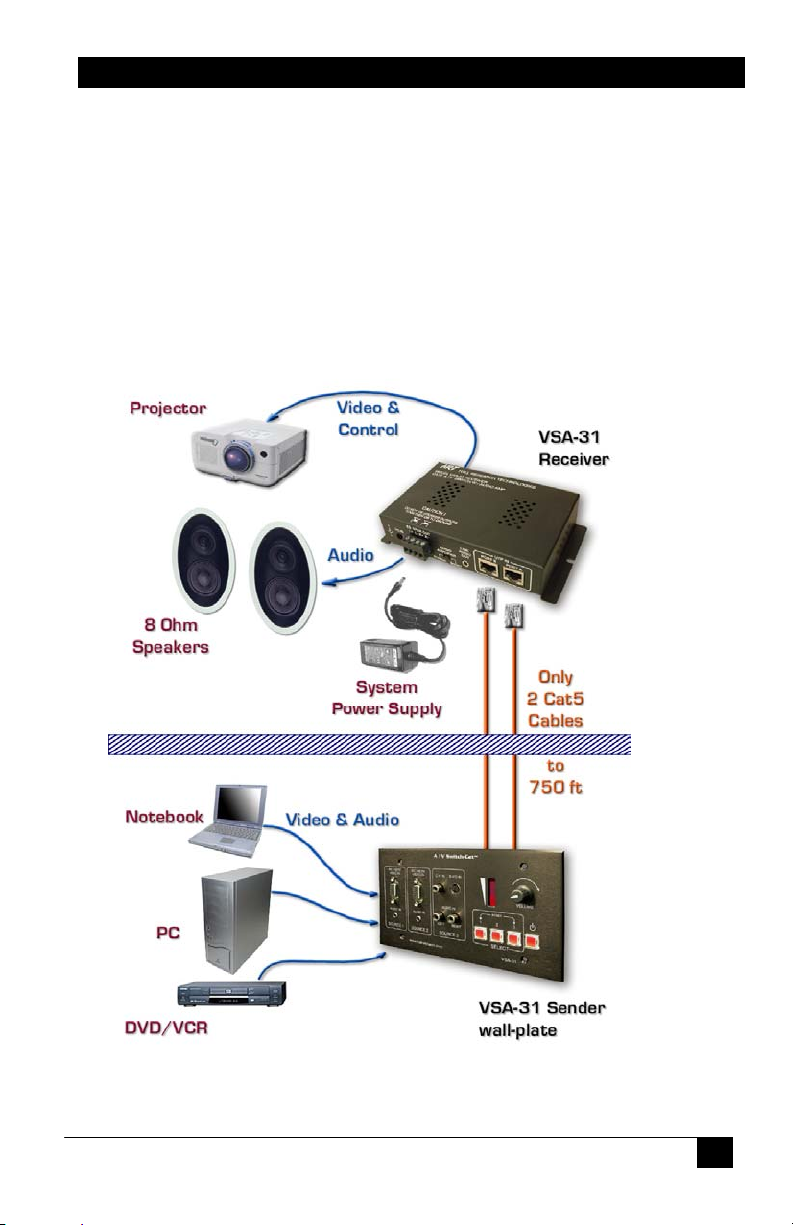
3.0 Installation
In a typical installation, the Sender unit is located on a wall or panel and
is wired to the remote Receiver unit via 2 Cat5 cables.
The sender qualifies as a low-voltage class 2 device and does not require
a J-box. In fact it does not even need a power supply to be connected to it,
as it draws power via the signal connection to the remote unit. However,
in most instances it is easier to use a standard 4-gang electrical box in
order to attach the faceplate to the mounting surface or structure.
Please contact HRT or your desired electrical supply house for purchasing
the J-box. These are generally inexpensive units.
TM
5
Page 6

Model VSA-31
As seen in the above diagrams, the connection between the receiver and
the projector are comprised of VGA, S-Video, and RS232. These cables
are not supplied and must be purchased separately.
Please note that most projectors use a unique and non-standard Serial
input connector, therefore you need to build your cable according to the
pin out provided be the projector manufacturer or purchase a cable from
them.
If you will be making your own cable, the VSA-31 receiver has the
following RS-232 pinout:
Connector on VSA-31: DB9-Male
Transmit: Pin 3
Receive: Pin 2
Ground: Pin 5
Note on video signals that go to the Projector
When you select either of the 2 VGA inputs, the VGA output
to the projector has the selected signal and the S-Video
output is blanked out. Conversely, if the input is Composite
Video or S-Video, only the S-Video output to the projector will
have a signal. This means that it is possible to use the
projector’s auto-detect mode to switch between video inputs
and not even connect the serial port to the projector.
However in doing so, you will not be able to use the on/off
button on the sender to control the projector, and you will
still have to rely on the projectors remote to turn it on and
off.
6
Page 7

A
/ V Switch-Cat
Prior to final installation of the wallplate, you need to use the supplied
Windows™ software and the serial cable to program the serial codes
needed to operate the projector into the sender wallplate.
Note on CV and S-Video Inputs
Do not connect the Composite Video and S-Video inputs
simultaneously. Doing so will produce a poor quality image
Note on RS-232 port availability on your PC
Most PCs and notebooks do not have a serial port. So to
program the sender you may need a USB to RS-232 Serial
converter. These are available from Hall Research Technologies
(Model USB-RS232-1).
TM
Note on Uploading Serial Codes
For your convenience the wallplate sender has a power
connector. In the final installation this connector will be left
open. However, you can use the power supply that is included
with the unit to solely power up the Sender (with no RJ45
connections) in order to upload the serial codes. Of course,
when the RJ45’s are connected, with the power supply at the
receiver, you can still upload the serial codes as well.
For more on the topic of Serial Control of the projector please refer to
Section 5.0
7
Page 8

Model VSA-31
4.0 Operation
The user’s operation of the system is almost self-explanatory. There are 4
buttons on the wall plate for powering the projector and selecting one of
the 3 A/V inputs.
The buttons are back-lit so you can tell which input is selected or if the
projector is turned on or not. If the command string being transmitted to
the projector has a ‘wait’ delay inserted, then during the prescribed wait
time, the LED will be blinking and the user cannot switch channels.
There is a volume knob on the sender with a corresponding LED bar to
indicate the current loudness setting.
The VSA-31 remembers the settings independently for each input. So as
you switch between inputs, the volume setting recalls the last setting of
that input.
Notes on Audio Output
The receiver has an “Audio Amplifier” switch with “Normal” and
“Boost” settings. For a small room use the “Normal” setting, for
larger rooms use the “Boost” setting. This is used to normalize
the loudness LED bar display, so in a small room where you
never would set the sound volume too loud, with the “Normal”
setting the LED bar display is not all the way to the bottom all
the time! Also note that if you use 4 Ohm speakers, the power
output from the system is maximized, so if you are using 8 Ohm
speakers, and in “Boost” you still don’t have sufficient loudness,
then you better switch to a lower impedance speaker such as 6
or 4 Ohm.
You can add more than one speaker to each of the Left or Right
output of the unit. If you are using 8 or 16 Ohm speakers, you
can parallel 2 of them on each channel (for a total of 4
speakers). If you are using 4 Ohm speakers, then you need to
put 2 of them in series for each channel (for a total of 4
speakers).
The VSA-31 receiver has a Line-level audio output. This
connector is used in cases where the built-in power amp may
not be sufficient. Upon connecting a plug to this jack, the power
amp outputs are disabled and you can route a stereo cable to
any external Audio Amp of your choosing. The volume knob on
the sender still acts on the level of the line output signal.
8
Page 9

A
/ V Switch-Cat
5.0 Windows™ Projector Configuration Software
Included in the VSA-31 package is a CD with the application that you
need to use to select your projector model in order to upload the
configuration serial parameters. This is a one time task, as long as you do
not change your projector. You can also create your own command string
set as explained below.
. Installing the Software
To install the software, load the CD into your PC and double-click on the
setup.exe file on the CD. The installation wizard will walk you through
the rest of the installation
. Selecting the Com Port
The VSA-31 Programming Software will detect your available COM
ports. Just select the COM port you will use to connect the VSA-31 to
your PC
TM
. Selecting your Projector Configuration file
Select your projector model from the drop down list. If your projector
model is not listed, contact Hall Research Technologies via the Request
button for your projector configuration file. You may also enter the
projector codes in a new configuration file if you would prefer.
9
Page 10

Model VSA-31
. Creating the Serial Strings
The serial string to the projector can be comprised of ASCII characters,
hexadecimal bytes, and wait times embedded in the strings. The length of
each serial string must not exceed 250 characters. The current length of
each string will be displayed in the String Length box. You will notice in
the Projector Commands drop down menu there are only 4 options. Select
the Projector command you wish to edit and then start typing the serial
string into the Serial String text box.
1. Source = VGA
This command will be issued when either one of the 2 VGA
inputs is selected via the VSA-31’s front panel buttons. This
command will tell the projector to select the VGA input.
2. Source = S-Video
The Source = S-Video command will be issued when the 3rd
input is selected. You will notice that the 3rd input can accept
either Composite Video or S-Video. The VSA-31 up-scales the
Composite video into S-Video so the projector is always
receiving S-Video when input 3 is selected. The serial command
associated with this command will tell the projector to select the
S-Video input.
10
Page 11

A
/ V Switch-Cat
3. Power = On
This command will be issued when the Power button is pressed
and the Power button LED is off. This command will instruct the
projector to power on.
Note: We recommend inserting a 15-45 second wait after the
power on serial command to allow the projector to completely
power up before sending it more serial commands. (Time to wait
will vary by projector)
4. Power = Off
This command will be issued when the Power button is pressed
and the Power button LED is on. This command will instruct the
projector to power off.
Note: We recommend inserting a 45-90 second wait to allow the
projector to completely power off before sending it more serial
commands. (Time to wait will vary by projector)
. Entering ASCII characters into the serial strings
Just start typing in either Serial Output text box to enter ASCII characters.
You will see the characters as you type. You cannot paste or copy text
and you cannot delete more than 1 character at a time. In the below
example I typed uppercase ABCDEFG
TM
. Entering hexadecimal bytes into the serial strings
Enter Hexadecimal bytes by typing the hexadecimal byte into the box
above the ‘Insert Hex Byte’ button. Then click ‘Insert Hex Byte’ button.
The Hexadecimal byte will be inserted at the end of the current string. In
this example I inserted the Hex byte FA
11
Page 12

Model VSA-31
. Entering wait times into the serial strings
Waits can be entered into the serial strings by choosing the wait duration
from the drop down menu then clicking ‘Insert Wait’ button. Each wait
uses the space of 2 ASCII characters in the overall string length. In this
example I inserted (2) 1-second waits for a total of a 2 second wait. When
a wait time is being executed by the VSA-31 you will see the button that
triggered that command blinking. During this wait period the VSA-31
will not accept user input from selection buttons.
. Entering Carriage Returns into the serial strings
To enter a Carriage Return <CR> into the serial string, just press the
‘Enter’ key on your keyboard. In this example I typed Test1 then I
pressed Enter then I typed Test2 then I pressed Enter again
12
Page 13

A
/ V Switch-Cat
. Selecting the Baud Rate and Parity
Select the Baud Rate the VSA-31 needs to use to communicate with the
projector from the drop down menu. Use a rate that matches your
projector. Choices are: 1200, 2400, 4800, 9600, 14400
57600 or 115200
use to communicate with the projector from the drop down menu. Use a
rate that matches your projector. Choices are: NONE, EVEN and ODD.
bits per second. Select the Parity the VSA-31 needs to
, 19200, 38400,
NOTE
Early versions of hardware only did not
support the baud
rates in BOLD TYPE above or any Parity selection.
Selecting an incompatible baud rate will result in the unit
defaulting to 9600 baud. Selecting any parity other than
“None” will result in the unit defaulting to None. Contact
Hall Research for more information.
. Setup to Program VSA-31
1. Install the VSA-31 Programmer software on the PC.
2. Connect power to the VSA-31.
3. Connect the VSA-31 to the PC via the supplied DB9-to-3.5 cable
4. Startup the VSA-31 Programmer software. (Located in Start menu)
5. Create the serial command strings
6. Save file and Upload
. Loading or Saving Configurations
You can save or load a configuration file by clicking on the File menu or
choosing the appropriate icon. You can also create a new configuration
file from the File menu or the New File icon
. Uploading to the VSA-31
To upload to the VSA-31, make sure the VSA-31 is connected to the PC,
via the supplied DB9-to-mini-stereo programming cable, and is powered
on then simply click on the Upload button
. Putting the VSA-31 into Operation
After you have successfully uploaded a configuration to the VSA-31
Transmitter, disconnect the VSA-31 Transmitter from the computer and
power it off. Connect the VSA-31 Transmitter to the Receiver via the 2
UTP (Cat5/5e/6) cables. When you connect power to the Receiver, you
will see the volume LED bar scroll from bottom to top several times to
indicate the boot up sequence. The VSA-31 is now ready select video
inputs and to adjust the volume.
TM
13
Page 14

Model VSA-31
. Operating the VSA-31
The volume level indicator will have every other LED turned on when the
VSA-31 is powered off. To operate the VSA-31, first press the power
button. The power button on the VSA-31 will now light up. If you have
uploaded a serial command for the “Power = On” command then that
serial command will now be issued to the projector. Next, select an input
1-3 by pressing the corresponding button. The button you just pressed
will light up and the serial command associated with that button will be
sent to the projector. In addition to issuing serial commands to the
projector the VSA-31 Transmitter will also switch the source of the video
being transmitted to the Receiver to the input you just selected. Only 1
video source will be transmitted to the VSA-31 at any given time. Adjust
the volume by turning the volume knob. You will see the volume level
indicated by the volume LED bar. Volume level is adjusted per input and
saved in memory for each input.
. Resetting the VSA-31
If for any reason you need to reset the VSA-31, press buttons 1 and 3
simultaneously and the unit will reset. This will not result in the loss of
any serial command programming this will only reboot the unit. All the
serial commands are still stored in the unit. You will need to press the
power on button and reselect the input you wish to display.
6.0 Troubleshooting
Make sure that all your connections are solid, and check the state of the
LED’s on the front of the unit. Do not open or try to repair the unit
yourself. There are no customer repairable items in the unit and you will
void your warranty.
Contact HRT Support at 714-641-6607 or via email or web. If you need
to ship your converter for repair, make sure to get a Return Material
Authorization (RMA) number first.
14
Page 15

A
/ V Switch-Cat
7.0 Specifications
Resolutions PC resolutions up to 1600x1200 @ 60 Hz & HDTV to
1080i, NTSC, PAL, or SECAM S-Video and CV
Video Level Unity Gain. 1V p-p for Y, 0.3 V p-p for C
Audio Level Variable Gain. 0 to +4dBu (0.78 to 1.23Vrms) line level
with Amplified outputs L + R at 6 Watts per Channel
Temperature Operating: 32 to 122°F (0 to 50°C);
Storage: –40 to +185°F (–40 to +85°C)
Enclosure Steel Receiver, Aluminum Sender
MTBF 90,000 hours (calculated estimate)
Power 12V DC from supplied universal power supply.
Size (WxDxH) Sender: 4.5" High x 8.2" Wide x 1.4” Deep
Receiver: 1.4" High x 3.6" Wide x 6.5" Long
Weight 2.1 pounds
TM
15
Page 16

Model VSA-31
Products Designed and Made in the USA
16
 Loading...