

Page 1
py
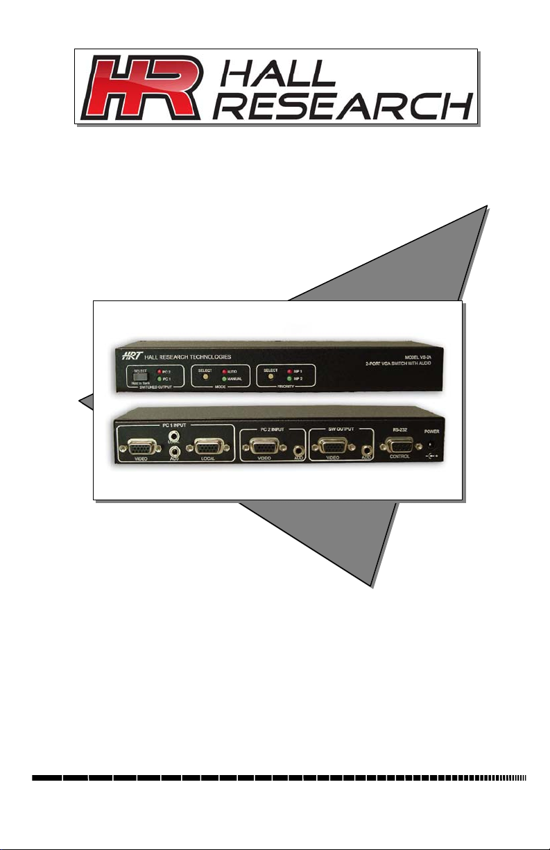
Model VS-2A
2-Port VGA Switch with Audio & Serial
Control
© Co
1163 Warner Ave Tustin, CA 92780, Ph: (714)641-6607, Fax -6698
right Hall Research, Inc. All rights reserved.
UMA1119 Rev B
Page 2

Model VS-2A
2
Page 3

Table of Contents
2-Port VGA Switch with Audio & Serial Control
1.0 General ................................................................................................ 2
2.0 Features................................................................................................ 2
3.0 Installation ........................................................................................... 3
. Required Cables..................................................................................... 3
. Inputs & Outputs ................................................................................... 3
. Connecting the VS-2A........................................................................... 3
. Connection Diagram.............................................................................. 4
4.0 Operation ............................................................................................. 4
. Switched Output .................................................................................... 4
. Modes of Operation ............................................................................... 5
. Front Panel Lockout .............................................................................. 5
. Priority Selection in Auto Mode............................................................ 5
. RS-232 Control...................................................................................... 6
. To configure HyperTerminal................................................................. 6
Control Codes (1 byte commands from external control device).............. 7
5.0 Troubleshooting................................................................................. 10
6.0 Specifications..................................................................................... 11
1
Page 4

Model VS-2A
1.0 General
Thank you for purchasing the Hall Research Model VS-2A 2-Port VGA
Switch with Audio & Serial Control.
This unit provides a video along with audio output that can be switched
between two video and audio sources. The unit also has a loop-out for PC
#1 Input for connection to a local LCD.
The VS-2A unit provides all the A/V and control connections on the rear
panel; the front panel has a push-button switch with corresponding LED
indicator for the selection of video source. The front panel also features
mode selection buttons to allow the unit to operate automatically (based
on video sync detection). This unit can be controlled either manually
using the front panel switch, automatically based on video sync detection,
or remotely through an RS232 serial port.
The unit can be configured to operate in two different modes, which are
Auto and Manual modes. There is a priority selection that can be used to
set for none, Input #1 or Input #2. Switched output can be blanked and
un-blanked either from the front panel button or from the PC command
sending through the serial port.
The unit also has EEPROM (internal non-volatile flash memory) to store
the last operating mode when power is off.
2.0 Features
9 Allows one video with stereo audio to be switched between two
video and audio sources
9 Loop-out for input #1 audio and video
9 Can be manually controlled by push-button switch buttons or
remotely by RS232 communication port
9 Provides Auto mode to automatically select input source
9 Auto Mode priority can be set for input #1, input #2 or no-priority
9 Switched output can be blanked and un-blanked
9 Stores the last selection and mode in EEPROM
9 Compact, Rugged, Reliable, and Economical
9 Made in USA
2
Page 5
2-Port VGA Switch with Audio & Serial Control
3.0 Installation
. Required Cables
The video input cables are generally HD15 (VGA) male to male
(customer furnished). The Audio inputs are 3.5 mm mini-stereo (also
customer furnished). If you are going to connect the unit to a Serial port
(such as PC’s COM) you would need a Male/Female DB9 Serial Cable.
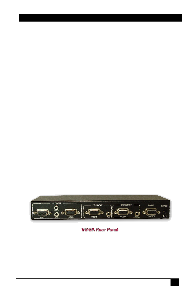
. Inputs & Outputs
The VS-2A has 2 video and audio inputs: PC 1 Input and PC 2 Input.
The unit has 1 video and audio output: SW Output. There is a local video
and audio output, which is a loop-out for PC 1 Input: Local.
. Connecting the VS-2A
Connect your video and audio sources such as computer or notebook PC
to PC 1 Input and PC 2 Input. If the loop-out for input #1 is desired, it
can be connected to local video and audio.
Connect the display device such as a monitor (or a video projector) to the
switched video and audio outputs (SW Output).
Connect the included power supply to the VS-2A.
Select the desired mode of operation including the priority for your video
and audio output using the front panel switched buttons. If preferred, the
selection can also be done through RS-232 serial commands by
connecting a DB9 RS-232 Serial cable to your PC and the VS-2A.
3
Page 6

Model VS-2A
. Connection Diagram
4.0 Operation
. Switched Output
The switched output SELECT button is used to select between video &
audio input sources of PC 1 and PC 2. A solid-on LED is used to indicate
which input is selected.
Holding down the switched output SELECT button for 3 seconds will
blank the current selected input source (and mute the audio output). The
LED for the current selected input will start blinking to indicate the
blanking mode. Pressing the SELECT button again will un-blank the
output and un-mute the audio on the switched out.
4
Page 7

2-Port VGA Switch with Audio & Serial Control
. Modes of Operation
The unit can operate in either Auto or Manual mode by pressing the mode
button to select it.
In Auto mode, the VS-2A will automatically select the input with active
video and audio. The presence of video is determined by examining the
V. Sync signal of the input connectors. The front panel SELECT button
cannot be used to switch between PC 1 and PC 2 input sources in this
mode. However, it can be used to blank the output by holding it down for
3 seconds or to un-blank the output by pressing it once.
In Manual mode, the output of the VS-2A will depend on the selection of
the switched output SELECT button.
. Front Panel Lockout
The Front panel controls can be locked so that the unit’s configuration
will remain unchanged until the front panel is unlocked or the
configuration is changed via the serial port.
To lock or unlock the front panel, hold the Priority Selection button for 3
seconds. All the front panel lights will flash to signify the status change.
If the units front panel is locked and the user presses any of the buttons,
the front panel led’s will flash rather than changing the selection.
. Priority Selection in Auto Mode
The priority button is used to select the priority as none, input #1 or input
#2. This priority selection only applies to the Auto mode. If "INP 1"
priority is selected, the VS-2A will automatically select input #1
whenever it detects the presence of video at the PC 1 input, regardless of
what is happening at input #2. If INP 2 priority is selected, the VS-2A
will automatically select input #2 whenever it detects the presence of
video at the PC 2 input, regardless of what is happening at input #1. For
example with INP 1 Priority set, if the output is playing the video & audio
from PC 2 input and the video from PC 1 input is detected, the output of
the VS-2A will select PC 1 (input #1) immediately. With priority set to
none, the unit stays selected to the current input as long as it is detecting
video there.
5
Page 8

Model VS-2A
. RS-232 Control
The VS-2A can also be controlled via a serial device. The unit operates at
a baud rate of 4800 bps. From the serial port, you have full control over
the operation of the switched output, mode, and priority buttons.
Note on RS-232 port availability on your PC
Most PCs and notebooks do not have a
serial port. So to program the Switch you
may need a USB to RS-232 Serial
converter. These are available from Hall
Research (Model USB-RS232-1).
The VS-2A will output a menu to a serial port on power-up. This menu
will also be displayed when a proper command is sent to it via a serial
port. To view the menu, An ASCII serial terminal or terminal emulator
software is needed. An example is Microsoft Windows HyperTerminal
(generally found in Accessories\Communication folder)
. To configure HyperTerminal
- Connect direct to COM1 or COM2
- 4800 Baud, 8 bits, No Parity, 1 Stop bit, No flow control
After power-up the unit will output a menu similar to below in ASCII
through its serial port:
--------------------- M E N U
---------------------1 = PC 1 Input
2 = PC 2 Input
F = Front Panel Lock
A = Auto Mode
M = Manual Mode
P = Priority Select
N = No Priority
B = Blank
U = Un-blank
S = Status Report
L = List Menu
----------------------
6
Page 9

2-Port VGA Switch with Audio & Serial Control
Control Codes (1 byte commands from external control device)
ASCII 1 (or Hex 31)
Selects input #1 (immediately and unconditionally). The
device will respond with: PC 1 Input selected
ASCII 2 (or Hex 32)
Selects input #2 (immediately and unconditionally). The
device will respond with: PC 2 Input selected
ASCII F (or Hex 46)
Toggles the Front Panel Lock Status. The device will
respond with: Front Panel Locked or Front Panel Un-
Locked
When the Front Panel is locked, no changes can be made via
the front panel buttons except to Unlock the Front Panel.
The Front Panel is Locked or Unlocked by holding the Priority
Selection Button for 3 seconds. All the front panel lights will
flash to signify the change in status.
ASCII A (or Hex 41)
Enters Auto mode. The device will respond with: Auto
mode
In Auto mode, the device automatically switches to the video
& audio input source that is active. “Active” means that video
signal has sync signal, it does not mean there is a non-static
screen!
ASCII M (or Hex 4D)
Enters Manual mode. The device will respond with:
Manual mode
In Manual mode, the device stays on the currently selected
video & audio, regardless of the presence of video signal.
7
Page 10

Model VS-2A
ASCII P (or Hex 50)
Toggles the Input Priority Selection. The device will
respond with: PC 1 priority selected or PC 2 priority
selected
If input #1 priority is selected, the unit will select input #1
automatically whenever the presence of the video at PC 1
input is detected even if the PC 2 input is currently playing.
If input #2 priority is selected, the unit will select input #2
automatically whenever the presence of the video at PC 2
input is detected even if the PC 1 input is currently playing.
ASCII N (or Hex 4E)
Selects no priority. The device will respond with: No
priority selected
ASCII B (or Hex 42)
Blanks the output. The device will respond with: Blanked
When the output is blanked, only the color intensities of the
output are reduced to zero, the unit still operates in normal
fashion and sync signals are still routed to the output. Audio
output is muted.
ASCII U (or Hex 55)
Un-blanks the output. The device will respond with: Unblanked
8
Page 11

2-Port VGA Switch with Audio & Serial Control
ASCII S (or Hex 53)
Request the status report. The device will respond with:
Status Report
-------------------------------Input = 1 (or 2)
Mode = Auto (or Manual)
Priority = 1 (or 2 or None)
Blank = On (or Off)
Front Panel Un-Locked (or Locked)
This report displays the current selection of switched output,
mode, priority buttons and Front Panel Lock Status.
ASCII L (or Hex 4C)
Displays the menu. The device will respond with:
--------------------- M E N U
---------------------1 = PC 1 Input
2 = PC 2 Input
F = Front Panel Lock
A = Auto Mode
M = Manual Mode
P = Priority Select
N = No Priority
B = Blank
U = Un-blank
S = Status Report
L = List Menu
This menu lists all the ASCII commands to control the VS-2A
unit via a serial port.
9
Page 12

Model VS-2A
5.0 Troubleshooting
There are no field serviceable parts or circuits in the device. If you think
that the device is malfunctioning, please first make sure that all your
connections are solid, and check the state of the LED’s on the front of the
unit to access the mode it is in.
If you still cannot overcome the problem, disconnect the video and audio
input connections from the unit. Unplug the power from the unit and after
a few seconds reconnect power. Connect your audio and video signals
after the unit is powered up. Check performance.
Do not open or try to repair the unit yourself. There are no customer
repairable items in the unit and you will void your warranty.
Contact the Hall Research Technical Support Department at 714-6416607 or via email or web. If you need to ship your switch for repair, make
sure to get a Return Material Authorization (RMA) number first.
10
Page 13

2-Port VGA Switch with Audio & Serial Control
6.0 Specifications
Video Inputs VGA, RGBHV, RGBS, RGsB, or Component Video
(YPbPr – would require HD15 to 3 RCA adapter)
Resolutions
Supported PC from VGA to UXGA (640x480 to 1600x1200)
HD from 480p to 1080p
Audio Inputs PC or Consumer audio (standard line-level)
Video Level 0 to 0.7V p-p on RGB, 0 to 5 V for H and V Sync
Bandwidth 200 MHz
Temperature Operating: 32 to 122°F (0 to 50°C);
Storage: –40 to +185°F (–40 to +85°C)
Enclosure Steel
MTBF 90,000 hours (calculated estimate)
Power 6V center positive via supplied Universal power supply
(100~240VAC).
Size 1.3” (33mm) H x 9" (229mm) W x 2.6” (66mm) D
Weight 1.1 pounds (500 grams)
11
Page 14

Model VS-2A
12
Page 15

Page 16

Product Designed and Made in the USA
 Loading...