

Page 1
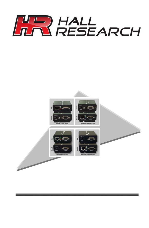
Model UV232A & UV232B
VGA + AUDIO + UNI-DIRECTIONAL RS232 (UV232A)
&
VGA + BI-DIRECTIONAL RS232 (UV232B)
SUPPORT &
ORDERING
INFORMATION
For technical support, Call 714-641-6607 or fax 714-641-6698
Order by phone: toll-free in the U.S. 800-959-6439
Web site: www.hallresearch.com
Hall Research, 1163 Warner Ave. Tustin, CA 92780
UV-232A
UV-232B
UMA1159 Rev. E
Page 2

Page 3
TRADEMARKS USED IN THIS MANUAL
Hall Research, HR, and its logo are trademarks of Hall Research.
Any other trademarks mentioned in this manual are acknowledged to be the
property of the trademark owners.
FEDERAL COMMUNICATIONS COMMISSION
RADIO FREQUENCY INTERFERENCE
STATEMENT
This equipment generates, uses, and can radiate radio frequency energy and if
not installed and used properly, that is, in strict accordance with the
manufacturer’s instructions, may cause interference to radio communication. It
has been designed to comply with the limits for a Class A computing device in
accordance with the specifications in Subpart B of Part 15 of FCC rules, which
are designed to provide reasonable protection against such interference when
the equipment is operated in a commercial environment. Operation of this
equipment in a residential area is likely to cause interference, in which case the
user at there own expense will be required to take whatever measures may be
necessary to correct the interference. Changes or modifications not expressly
approved by the party responsible for compliance could void the user’s authority
to operate the equipment. This digital apparatus does not exceed the Class A
limits for radio noise emission from digital apparatus set out in the Radio
Interference Regulation of the Canadian Department of Communications.
3
Page 4
VGA – AUDIO – RS232 EXTENDERS
Contents
1. Introduction.................................................................. 2
1.1 General................................................................... 2
1.2 Features.................................................................. 3
2. Installation ................................................................... 3
2.1 Connecting the UV232A / B.................................. 3
3. Configuration and Operation ....................................... 5
3.1 Adjusting the video quality for long cable runs..... 5
3.2 UTP Cable Recommendations............................... 6
4. Troubleshooting .............................................................. 7
4.1 Contacting Hall Research ...................................... 7
4.2 Shipping and Packaging ........................................ 7
5. Specifications.................................................................. 8
1. Introduction
1.1 General
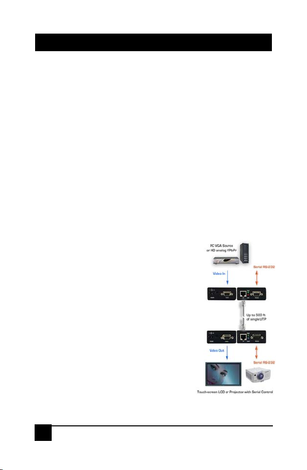
Hall Research’s Model UV232A and UV232B kits
are members of HR’s powerful video product line.
The model UV232A kit extends VGA/HD video,
audio (L+R Mixed), and unidirectional RS-232 over
a single Cat5 cable, while the model UV232B kit
extends VGA/HD video and bi-directional RS-232.
2
Figure 1 – UV232B Block Diagram
Page 5
Model UV232A & UV232B
1.2 Features
Sends PC or HD video, audio (L+R mixed), and unidirectional RS-232
over single Catx (Model UV232A)
Sends PC or HD video and bi-directional RS-232 over single Catx
(Model UV232B)
Wide bandwidth to transmit WUXGA signals (1920x1200 / 60hz) or HD
Analog Component (1080p)
Compensation for UTP cable to 500 ft.
No power supply required for local unit – powered from VGA source
DDC compliant EDID emulation on the Sender
Supports all baud rates to 115Kbps
Perfect for touch-screen (UV232B), Kiosk, or Projector Control
applications.
RS-232 and high quality VGA input cables provided
Compact metal enclosure with mounting provisions
Compact, Rugged, Reliable, and Economical
Made in USA
2. Installation
2.1 Connecting the UV232A / B
3
Page 6

VGA – AUDIO – RS232 EXTENDERS
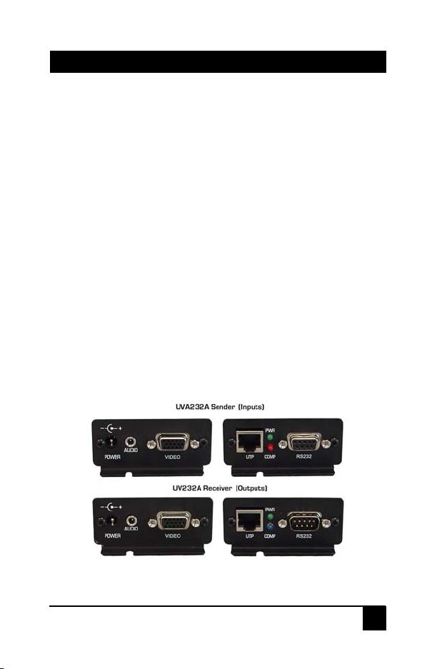
1. Connect video source to Sender unit using supplied VGA cable. Connect the
RS-232 serial using supplied straight-through DB9 male/female cable. Connect
line-level audio to mini-stereo jack (UV232A only).
Note
: The Sender unit receives power from the VGA source
per VESA standard (+5v on pin 9). If the source is not VESA
compliant in that regard, or if the video is YPbPr (using a 3
RCA to HD15 input cable), then a power supply would be
needed at both ends. Two power supplies are included for this
purpose.
2. Connect the Sender’s RJ45 port to the Receiver unit using straight-through
UTP or STP cable directly to the receiver. IMPORTANT:
the Cat5 cable to any other manufacturer’s device or network equipment.
3. Connect the Receiver to the display device, and use a straightthrough RS-232 cable to connect the receiver to the remote serial
device (e.g. touch-screen (UV232B), projector, etc). Connect audio
output to powered speakers (UV232A only).
CAUTION
Maximum Recommended Cable Lengths
Table 3.1
Before applying power to the remote unit, verify that the AC
line is properly wired and that a protective ground (green) wire
is established with NO potential difference between both the
sender and receiver locations. The extender can tolerate up to
5v peak-to-peak ground potential between the two locations.
Failure to ensure good grounding can result in erratic operation
and possible shock hazards or damage to your equipment.
4. Power receiver using included power supply; check green Power LED on
sender to verify it is receiving power from VGA source. Using a small
screwdriver; turn the compensation potentiometer CW for more compensation or
CCW for less, until the image is perfectly clear.
You cannot connect
4
Page 7
Model UV232A & UV232B
3. Configuration and Operation
3.1 Adjusting the video quality for long cable runs
The video quality at the remote station depends on: (1) the length of the CAT5
cable, (2) video resolution setting, (3) refresh rate setting and the model of the
receiver.
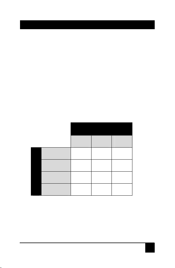
In general, at low and mid resolutions, excellent image reproduction is provided
at up to 500 feet. At high resolution and refresh rates perfect image reproduction
can be achieved at shorter distances (see table below). Using longer cables or
higher resolution rates will still produce an image, but the reproduction quality
will be reduced.
Maximum Recommended Cable Lengths
Table 3.1
Refresh Rate
60 Hz 75 Hz 85 Hz
800x600 500 ft 500 ft 500 ft
1024x768 500 ft 450 ft 400 ft
1280x1024 400 ft 350 ft 300 ft
Resolution
1600x1200 300 ft 300 ft 300 ft
5
Page 8
VGA – AUDIO – RS232 EXTENDERS
3.2 UTP Cable Recommendations
RED
RED
BLUE
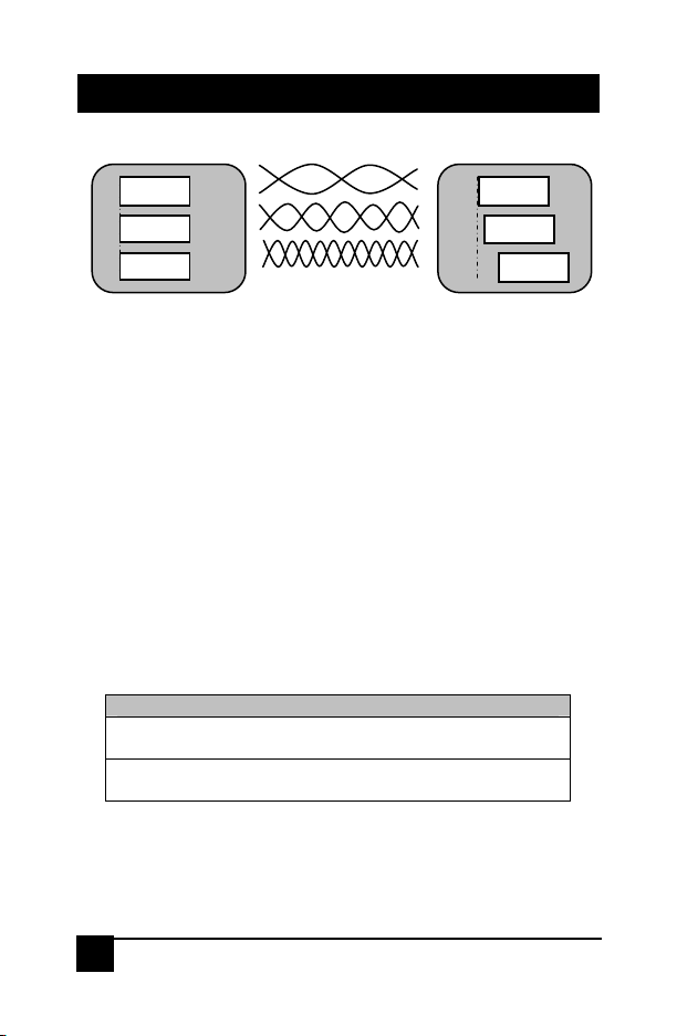
UTP cables have 4 twisted pairs inside. The video transmission over UTP uses
3 individual pairs for each color (Red, Green, & Blue). As shown in figure 3.2
above, a characteristic of Category-5/5e/6 cable is that the pairs of wires are
twisted at different rates. Therefore, for a given length of Cat-5 cable the total
length of a particular pair could be longer than others. Since the signals travel in
the cable at a fixed speed, the arrival times of signals can be skewed in a long
cable (those that have to travel farther arrive later and the corresponding color
shifts to the right).
This is seen on the monitor as separation, or lack of convergence in colors. For
example a vertical white line on the screen may look to have a red tinge on the
left edge and blue tinge on the right edge.
This effect gets worse at high resolutions, high refresh rates, long cables (in
excess of 200 feet), and depends on the cable construction itself. Hall Research
highly recommends the use of UTP cables specifically constructed for video
transmission. In these cables the all the twisted pairs are the same length. They
are available from several sources including Hall Research (part numbers
shown below).
Zero-Skew CAT5 Cable for use with Hall Research CAT5 Products
PART NUMBER
CUTP-Z-1000-BLK 1000 ft.
Zero-Skew CAT5 cable. Bulk spool of 1000 ft
CUTP-ZP-1000-BLK 1000 ft.
Zero-Skew CAT5 cable. Bulk spool of 1000 ft Plenum Rated
If you are going to use commercial grade UTP cable, then we recommend using
Cat5 or Cat5e rather than Cat6, since the twist ratio match is better in Cat5
cable.
Figure 3.2
6
Page 9

Model UV232A & UV232B
4. Troubleshooting
Most common problems are caused by the following:
• Confusing the Sender and the Receiver
• Using a Cat5 cable that is too long, not straight through, or not
terminated properly
• Not connecting the power supply, or it is not powered
• Display device does not support the resolution that is being sent (in
which case you should check operation without the extender first)
4.1 Contacting Hall Research
If you determine that your extender is malfunctioning, do not attempt to repair
the unit. There are no user serviceable parts inside the unit. Opening the unit
will void the warranty. Contact HR’s Tech. Support at 714-641-6607 to obtain an
RMA (Return Authorization) number.
Before you do, make a record of the history of the problem. We will be able to
provide more efficient and accurate assistance if you have a complete
description
4.2 Shipping and Packaging
If you need to transport or ship your device:
.
• Package it carefully. We recommend that you use the original container if
possible.
• Before you ship the units back to Hall Research for repair or return,
contact us to get a Return Authorization (RMA) number.
7
Page 10

VGA – AUDIO – RS232 EXTENDERS
<
5. Specifications
Standards Analog VGA Video (RGBHV), YPbPr, or RGB
Resolutions All up to WUXGA (1920x1200 / 60Hz), 1080p
Video Level 0.7 v p-p on RGB, 5v p-p H/V sync
Bandwidth 20 Hz to 450 MHz
Common Mode
Noise Rejection 100 dB @ 60 Hz, 70 dB @ 1 MHz, 50 db @ 10 MHz
Max Distance Up to 500 ft. (152 meters) - See table 3.1 for details
Temperature Operating: 32 to 122 Deg F (0 to 50 Deg C);
Storage: -40 to +185 Deg F (-40 to +85 Deg C)
Enclosure Aluminum
MTBF 100,000 hours (calculated estimate)
Power Via the included power adapters. Voltage: 6v DC
Size (H x W x D) 1.25” H x 2.75” W x 3.08” D* Each Device
*Units have 2 mounting ears that protrude 0.40”
RS232 Connections
J2
1
6
2
RX<-
7
3
TX->
8
4
9
5
GND
DB9F – RECEIVER
signals with sync-on-green.
Center-Positive. Average Power Consumption:
200mA (Sender) 160mA (Receiver)
beyond the main box on each side.
1
6
2
-TX
7
3
->RX
8
4
9
5
GND
SENDER – DB9M
8
Page 11

Page 12

© Copyright 2009. Hall Research
All rights reserved.
1163 Warner Ave., Tustin, CA 92780
Ph: (714)641-6607, Fax: (714)641-6698
 Loading...