

Page 1

Miniature Video-over-CAT5 Extension System
Model UV-1 VGA Extension
Model UV-1-CP
Model UV-1-CV
Component Video (RGB or YPbPr) Extension
Composite Video and Stereo Audio Extension
INFORMATION
CUSTOMER
SUPPORT
Order toll-free in the U.S. 800-959-6439
FREE technical support, Call 714-641-6607 or fax 714-641-6698
Mail order: Hall Research, 1163 Warner Ave., Tustin, CA 92780
Web site: www.hallresearch.com • E-mail: info@ hallresearch.com
UMA1053, Rev. A
Page 2

Page 3

Miniature VGA over CAT5 Extension System
ss
TRADEMARKS USED IN THIS MANUAL
Hall Research, HR, and
are trademarks of Hall Research, Inc.
IBM is a registered trademark of International Business Machines Corporation.
Any other trademarks mentioned in this manual are acknowledged the
property of the trademark owners.
FEDERAL COMMUNICATIONS COMMISSION
RADIO FREQUENCY INTERFERENCE STATEMENT
This equipment generates, uses, and can radiate radio frequency energy and if not installed
and used properly, that is, in strict accordance with the manufacturer’s instructions, may
cause interference to radio communication. It has been designed and found to comply with
the limits for a Class A computing device in accordance with the specifications in Subpart B
of Part 15 of FCC rules, which are intended to provide reasonable protection against such
interference when the equipment is operated in a commercial environment. Operation of this
equipment in a residential area is likely to cause interference, in which case the user at his
own expense will be required to take whatever measures may be necessary to correct the
interference.
Changes or modifications not expressly approved by the party responsible for compliance
could void the user’s authority to operate the equipment.
This digital apparatus does not exceed the Class A limits for radio noise emission from digital
apparatus set out in the Radio Interference Regulation of the Canadian Department of
Communications.
1
Page 4

Miniature VGA over CAT5 Extension System
Contents
1. Introduction.................................................................................3
1.1 Model UV-1 (for VGA)........................................................3
1.2 Model UV-1-CP (for Component Video (RGB or YPbPr)) .3
1.3 Model UV-1-CV (for Composite Video and Stereo Audio).4
1.4 Features.................................................................................4
2. Installation ..................................................................................5
Recommended Power Supply Connection..................................6
3. Configuration & Operation .........................................................7
4. Troubleshooting ..........................................................................9
Contacting Hall Research..........................................................10
Shipping and Packaging............................................................10
5. Specifications............................................................................11
2
Page 5

Miniature VGA over CAT5 Extension System
ss
1. Introduction
1.1 Model UV-1 (for VGA)
The Model UV1 is a single channel UTP (CAT5) VGA video extender consisting of
a sender (UV1-S) and a receiver (UV1-R) sold together as a pair. The sender
converts a PC's VGA signal into a format that can be transmitted using a single
inexpensive and commonly available Category-5 Unshielded Twisted Pair (UTP)
cable with RJ45 connectors, which is used in most Local Area Networks.
At the receiving (remote) end, the Cat5 signal is converted back to VGA for
connection to your monitor, projector or other display device.
The sender and receiver are housed in a small plastic enclosure and include a
HD15 video connector and a RJ45 connector for the Cat-5 cable. Included with the
pair of devices are: one small power adapter (can be powered at either end), and
a short adapter cable for easy connection to the standard HD-15 connector of the
PC.
The Mini-Cat® brand extenders can drive CAT5 LAN cables to 500 feet (150
meters) with little to no degradation of video quality
1.2 Model UV-1-CP (for Component Video (RGB or
YPbPr))
This variation of the UV-1 includes cables for each end that allow you connect the
sender to the 3 RCA connectors of DVD-players or other video sources that output
Component Video (RGB or YPbPr, or YCbCr) and the receiver to connect to
compatible displays such as HDTV’s or high-end monitors. The actual sender and
receiver units are identical to the standard UV-1 and, in fact, you can use the pair
to send VGA video if you substitute VGA cables.
.
3
Page 6

Miniature VGA over CAT5 Extension System
1.3 Model UV-1-CV (for Composite Video and Stereo
Audio)
This variation of the UV-1 includes cables for each end that allow you to connect
the sender to the composite Video (Yellow), Left Audio (White) and Right Audio
(Red) connectors of your A/V equipment. It can actually send the signals in excess
of 2000 feet (609 meters), though both ends need to be powered if the distance is
beyond 500 ft.
Unlike the UV-CP, the UV-1-CV is not compatible with VGA signals.
1.4 Features
• Eliminates the need for bulky, expensive and hard to build multi-coaxial
cables for High-Resolution A/V extension
• Amplifies the signal for clean and crisp transmission
• Differential signaling eliminates ground loops and noise
• Handles resolutions up to 1920x1440 at 60 Hz
• Rugged, Reliable, Compact size
• Only one end requires power in most applications. The power supply
connects at either the sending or the receiving end, whichever is most
convenient based on cable length.
• Drive standard CAT5 cables to 500 feet for (VGA and Component video
versions) or to 2000 feet for (Composite Video and Stereo Audio
version)
• Available with EDID Emulation, both Standard and Custom
Programming available
4
Page 7

Miniature VGA over CAT5 Extension System
ss
2. Installation
1. Connect the VGA in (HD-15) connector of the UV1-Sender to the computer's
video port using the supplied cable (see figure 2.1).
Figure 2.1
2. Connect the supplied power adapter to the power input connector on either of
the units. Note that only one power adapter is normally needed to power both
the sender and receiver. It can be plugged into either the sender or receiver.
Please be sure to insert the power connector fully. You may need to push
down on the connector as shown below. Check the red light next to the RJ45
connector to verify unit’s power.
5
Page 8

Miniature VGA over CAT5 Extension System
Recommended Power Supply Connection
Cat 5 cable length of 0 to 150 feet:
It does not matter in which end you plug the power supply. Do whatever
is most convenient for your setup.
Cat 5 cable length of 150 to 300 feet:
We recommend that you plug the power supply at the receiving end.
Cat 5 cable length of 300 to 500 feet:
You should plug the power supply at the receiving end, however,
depending the grounding of the video source (PC) and the display
device at the remote end, you may need to purchase an additional
power supply to power up both ends.
Cat 5 cable lengths over 500 feet:
Purchasing an additional power supply to power up both ends is almost
certainly required.
3. Using Category-5 cable connect the UV1-Receiver to the unit's RJ45 output.
Connect the remote monitor to the receiver.
6
Page 9

Miniature VGA over CAT5 Extension System
ss
IMPORTANT
Do not connect this unit to any LAN device such as network cards or
hubs as this may cause damage. Use EIA/TIA 568B standard straightthrough patch wiring as shown below. Do not use crossover cables.
EIA/TIA 568B WIRING STANDARD
PIN Wire Color
1 White w/ Orange Stripe
2 Orange
3 White w/Green Stripe
4 Blue
5 White w/Blue Stripe
6 Green
7 White w/Brown Stripe
8 Brown
3. Configuration & Operation
The Mini-Cat® Receivers are equipped with an adjustment to improve image
quality when using long cables. The adjustment is made via a single turn trim-pot
located next to the power connector on the receiver.
7
Page 10
Miniature VGA over CAT5 Extension System
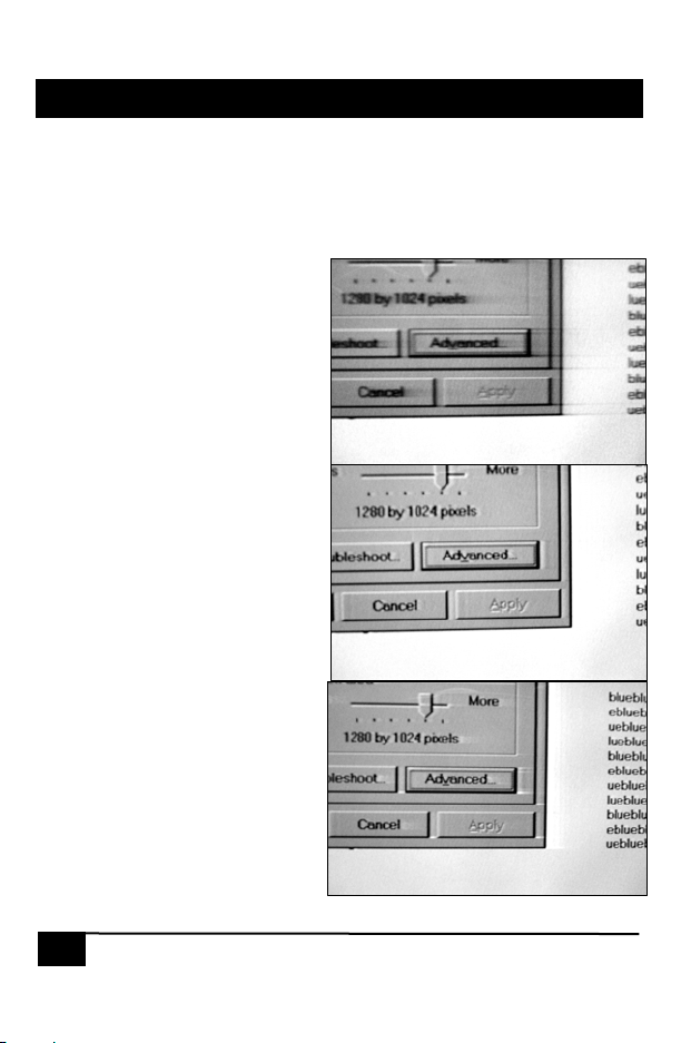
When using a long cable with no compensation, any solid horizontal lines tend to
smear to the right. For example in the image shown, observe the dark black line at
the bottom of the window and see how it is smearing to the right (not changing to
white abruptly as it should). This is the effect of long cable on the signal.
You can turn the trim-pot to
eliminate these streaks as shown on
the second picture. If you add too
much compensation to the signal,
then an opposite effect may be
observed, i.e. black lines smear to
the right as white lines or vice-versa.
The third picture shows the case
where too much compensation is
added.
In general, when using long cables,
the image quality is a function of
resolution and refresh rate. If
possible, set the refresh rate to 60
Hz at any resolution.
Also for best results at long
distances, try to use standard
Category-5 Cable (instead of CAT5e
or CAT6 since CAT5e and CAT6
cables may have widely dissimilar
twist ratios of the wire pairs in the
cable that may result in noticeable
color skew).
No-Compensation
Perfect Compensation
Figure 3.1
Too much Compensation
8
Page 11

Miniature VGA over CAT5 Extension System
4. Troubleshooting
1. Fuzzy, blurry, or ghosting image at remote location
If you have a stable image but it looks somewhat blurry (object or character
edges are not sharp), try to adjust the compensation first. When the trim-pot
is turned fully CCW there is no compensation. As you turn the pot clockwise,
you are applying compensation. Look at the screen and slowly turn the pot
clockwise. Notice what happens to the right of solid horizontal lines (as in
figure 3.1). If you still have a fuzzy image, try reducing first the refresh rate
and then the resolution of the PC.
2. Shaking image or periodically blanking monitor
Although CAT5 cable uses twisted pairs to transmit the signals from the
splitter to the receivers to reduce the amount of EMI coupled noise from
external sources, a strong electromagnetic noise field can cause instability in
the signal. Usual sources of this form of noise coupling are high current AC
lines or other high-density data and/or control cables that run adjacent to and
parallel with a substantial length of the CAT5 cable.
To eliminate this, either separate the Cat 5 cable of Mini-Cat® from the
interfering source or use shielded CAT5 cables. Note that separating the
CAT5 cable from the EMI source by a few inches is often sufficient to
eliminate this problem.
3. The PC does not recognize a Plug-and-Play monitor
If the PC’s operating System is setup to detect a plug-and-play monitor
(usually in Display Properties Advanced Settings), it may have trouble finding
a monitor. If the PC does not produce an image due to this, disable the plugand-play monitor detection in the PC’s operating system Display properties.
4. Substituting power supplies
The sender and receiver rely on the power adapter that is supplied with them.
Do not substitute any other power supply or DC power source
ss
9
Page 12

Miniature VGA over CAT5 Extension System
Contacting Hall Research
If you determine that your extender is malfunctioning, do not attempt to repair the
unit. Contact Hall Research’s Technical Support Department at 714-641-6607.
Before you do, make a record of the history of the problem. We will be able to
provide more efficient and accurate assistance if you have a complete description.
Shipping and Packaging
If you need to transport or ship your extender:
• Package it carefully. We recommend that you use the original container.
• Before you ship the units back to Hall Research for repair or return, contact
us to get a Return Authorization (RMA) number.
10
Page 13

Miniature VGA over CAT5 Extension System
5. Specifications
Standards VGA, SVGA, XGA, or UXGA video
Video Types VGA through UXGA, RGBS, RGsB (sync on “green”), or
YPbPr
Resolution Up to 1600 x 1200 non-interlaced at up to 85 Hz
Bandwidth DC to 250 MHz
Max. Distance Up to 500 ft. (150 m) for VGA and Component Video models,
or 2000 ft (609 m) for Composite Video and Stereo Audio
models
Connectors HD15 female for video in and out; Shielded RJ45
Interfaces Standard Analog VGA; Proprietary CAT5
Compliance Meets requirements for CE; FCC Part 15 Subpart B Class A,
IC Class
Max. Altitude 10,000 ft. (3048 m)
Temperature Operating: 32 to 122°F (0 to 50°C);
Storage: –40 to +185°F (–40 to +85°C)
Humidity Up to 95% non-condensing
Enclosure Plastic ABS-94VO, UL File#56070
MTBF 300,000 hours (calculated estimate)
Power From utility-power (mains) outlet, through included external
power adapter. Output Voltage: 9v DC Center-Positive.
Current requirement 500-mADC max
Size UV1-Sender & UV1-Receiver 0.8H X 1.7W X 4.5L
Weight 2 lbs. (shipping)
ss
11
Page 14

Miniature VGA over CAT5 Extension System
12
Page 15

Page 16

Products Designed and Made in the USA
© Copyright 2009. Hall Research, Inc.
All rights reserved.
1163 Warner Ave., Tustin, CA 92780
Ph: (714)641-6607, Fax: (714)641-6698
 Loading...