

Page 1
Software GUI
CUSTOMER
SUPPORT
Rev 1.2
User’s Manual
INFORMATION
Manager Software
for the UHBX-SW3-WP
Auto-Switching Wall Plate
FREE support, Call 714-641-6607 or email support@hallresearch.com
Hall Research, 1163 Warner Ave., Tustin, CA
Web site: www.hallresearch.com
92780
UMA1229 GUI Supplement
Page 2

Table of Contents
1. WINDOWS™ SOFTWARE INSTALLATION 1
1.1. General 1
1.2. Installation Prerequisites 1
1.3. Installing the Software 1
2. USING THE SOFTWARE 2
2.1. General 2
2.2. USB Device Detection 2
2.2.1. USB Connection Status 2
2.2.2. USB Device Name 3
2.3. Configuration Pages 3
2.3.1. On/Off Control Page 4
2.3.2 Video 7
2.3.3 EDID 11
2.4 Operation Mode 12
2.5. Tool Bar Menu 13
2.6. Firmware Update 14
Appendix 1 - Serial Commands in Slave Mode 15
Trademarks
Hall Research and its logo are trademarks of Hall Research Technologies, Inc. All other
trademarks mentioned in this manual are acknowledged as the property of the trademark
owners.
Page 3

1
© Copyright 2015. Hall Research, Inc.
UHBX-SW3-WP
1. Windows™ Software Installation
1.1. General
The UHBX-SW3-WP graphical user interface (GUI) is a Windows® software used to
configure advanced settings of the UHBX-SW3-WP. Use of the software requires USB
connection of the PC to the device. For convenience, a USB cable is provided with the
wall plate.
After configuring the wall plate, the user can save the desired configuration as a file on
their PC. Configuration files can also be uploaded to wall plate.
1.2. Installation Prerequisites
• PC with Windows XP™ OS or later
• USB port
• Microsoft™ .NET Framework 2.0 or later (most recent OS including Windows 7 and
8 typically include this and no action is required). If .NET Framework 2.0 or later is
not installed on your PC, the Microsoft™ website has free downloads available.
1.3. Installing the Software
• If an earlier version of this software was previously installed, UNINSTALL the
program first from either the Add/Remove Programs section of the control panel or
by running the previous installation SETUP.EXE and selecting “remove application”.
• Install the software by executing the SETUP.EXE program from the installation
source directory
• Accept the default settings, but if you want to specify a particular installation
directory other than the default, you may do so.
• Once the UHBX-SW3-WP software installation has completed, either click the
desktop icon
or from the Start Menu:
Start Programs Hall Research UHBX-SW3-WP
All rights reserved.
Page 4
Software Guide
2
© Copyright 2015. Hall Research, Inc.
For the PC to communicate with the wall plate, the UHBX-
2. Using the Software
2.1. General
The UHBX-SW3-WP Manager is a Windows software that can be used to configure the
auto-switching wall plate via a USB connection.
It provides the ability to configure power commands using either RS232 or IR protocols.
If an optional SW3-UI-VOL auxiliary control keypad with Volume buttons is used, the GUI
also allows definition of Volume UP/Down, Mute, and Unmute commands.
The GUI also allows tweaking of parameters such as: prioritizing the inputs in Auto
Source mode, locking or unlocking the Auto modes, and controlling the VGA Scaler's
parameters such as underscan (zoom out), aspect ratio, brightness, etc.
The GUI can save and load a configuration file into or from the device, and can be used
to easily update firmware in the UHBX-SW3-WP.
2.2. USB Device Detection
The Manager Software automatically configures the USB port after connection to the
device. No special USB driver installation is required by the user.
The first time you connect the device to a PC, you may experience a short delay while
Windows automatically installs the required USB drivers. This only happens once.
Notice
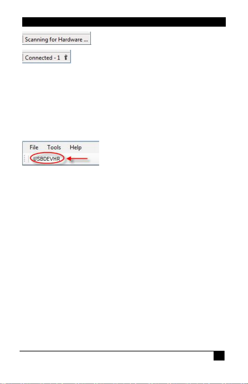
2.2.1. USB Connection Status
The GUI shows USB connection status and the number of detected SW3 wall plates on
the bottom right corner of the status bar. If no USB device is detected the Status bar
shows a message indicating that the GUI is waiting for a connection as shown below.
SW3-WP needs to be receiving power through its HDBaseT
Cat6 cable (POH). So it needs to be connected to a PSE
receiver such as UHBX-R-PSE.
If you start the Manager software without the USB port
attached, the on-screen fields are disabled (grayed out).
The instant you connect the USB cable, the GUI fields will
become active.
All rights reserved.
Page 5
3
© Copyright 2015. Hall Research, Inc.
UHBX-SW3-WP
GUI is waiting for USB connection to wall plate
GUI has detected one device connected
2.2.2. USB Device Name
You can assign a unique USB device name to each wall plate. The device names are
stored on the wall plates. By default all wall plates are called USBDEVHR as shipped but
if you are going to configure a number of wall plates differently, then you may wish to
assign different names to them that indicates room number or configuration type.
The USB device name is shown near the top right of the screen under the toolbar. Click
to change the name. A maximum of 8 characters can be used.
2.3. Configuration Pages
There are 3 configuration pages:
•
On/Off Control - can be used to:
o Define RS232 (or simple IR) commands for controlling the volume of
the display (for use with SW3-UI-VOL auxiliary keypad).
o Defining the Auto/Manual mode of Power Command
o Locking the Power Command in Auto mode
Video - can be used to:
•
o Assign priorities to the 3 video inputs for Auto Source selection mode
o Defining the Auto/Manual mode of Source Selection
o Locking the Source Selection in Auto mode
o Configuring the VGA Scaler
o Configuring and monitoring the HDBaseT® output
EDID - can be used to:
•
o Use an internal "emulated" or pass-thru the EDID from the display
All rights reserved.
Page 6
Software Guide
4
© Copyright 2015. Hall Research, Inc.
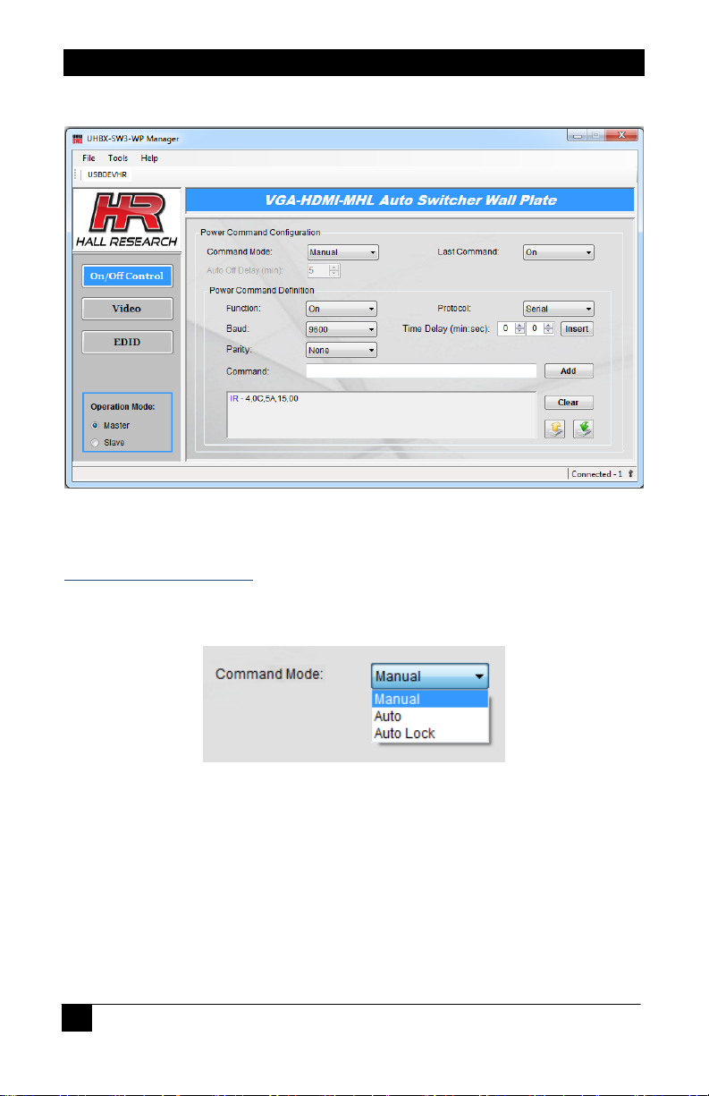
2.3.1. On/Off Control Page
The UHBX-SW3-WP Manager provides you more control and flexibility of the device than
the front panel.
Power Command Mode
For sending on/off power commands to the display, there are two different modes the
UHBX-SW3-WP device can be set to: manual and auto
Manual – In this mode, each Power button press on the physical wall plate (or using
the Last Command dropdown from GUI) will alternate between sending the Power
On or the Power Off command to the display.
Auto – When the device is set in this mode, it will automatically issue power
commands based on detecting video on the selected input. As soon as a video
source is plugged in to the selected input, the device will send out the preconfigured power on command, and after video is disconnected, the wall plate will
wait for some time (typically 5 minutes), and issues the power off command.
All rights reserved.
Page 7

5
© Copyright 2015. Hall Research, Inc.
UHBX-SW3-WP
Auto Lock – This is the auto mode as mentioned above with lock enabled, which is
locking the user from using the wall-plate power button to switch it to the manual
power mode. If you want to keep users from being able to inadvertently disabling the
Auto mode, you can lock it from the GUI. The only way to exit the lock mode is
through using the GUI.
Last Command
The last command is only enabled in the manual power mode. It has the same effect as
pressing the power button on the wall plate. It toggles power on the wall plate and causes
it to also issue on or off commands to the display.
When the device is turned off, all LEDs will be off. When it is turned on, it will return to its
previous state before shutdown.
Auto Off Delay
When Power Command mode is set for Auto, and there is no video being detected, the
auto off delay is defined as the time the device will wait for video to show up before
sending out the pre-configured power off command to the display.
After receiving a Power Off command, some projectors ignore further commands for
some period of time (typically 30 seconds to a minute). We recommend that the user test
their projector and determine the time it needs to get ready to process commands. Then
you can enter a time delay as part of the Off Command string. This way, if just after
sending the off command the video is reconnected, the wall plate will wait for the inserted
delay to expire before issuing the On command (without the Delay in the off command,
the On command may not be received).
Power Command Definition
The UHBX-SW3-WP allows the user to configure power ON and OFF commands using
either RS232 serial or IR. IR can only be used if the exact protocol of the IR (such as
RC5, NEC, etc) and the address and data bytes for the button are known. This
information is typically hard to come by! We recommend using IR only if you are 100%
All rights reserved.
Page 8

Software Guide
6
© Copyright 2015. Hall Research, Inc.
certain and verified that you have such information. Furthermore, even if that information
is available, if separate
the system out of sync with the display. Therefore, it is highly advised to use RS232
whenever possible. Also remember that the wall plate does provide an IR detector and
for simple installations, the user can just point the remote to the wall plate and extend it
to the display.
A command can be up to 40 bytes long, and it can be a combination of serial, IR, and
delay commands.
Function – It is used to select an on or off command to configure.
Protocol – It consists of serial and IR to use for a protocol.
Serial Commands
A serial command can send data to any standard serial device with selectable baud
rate and parity.
Hexadecimal characters may be entered by using &h in front of the 2 digit
hexadecimal character (e.g. &hbe&hef&h00&h00&h01).
Commands are entered in the command text box. When done, you can click the
Add button to append the command as shown in the figure above.
On and Off IR commands are not provided, it is possible to get
IR Codes
As cautioned above . IR can only be used if the exact protocol of the IR (such as RC5,
NEC, etc) and the address and data bytes for the button are known.
Supported IR formats are: NEC, JVC, RCA, RC5, Sony, and Extended NEC.
Select the desired IR protocol and enter address along with command. When done,
just click the Add button to append the command.
All rights reserved.
Page 9

7
© Copyright 2015. Hall Research, Inc.
UHBX-SW3-WP
Inserting Delays in Commands
A time delay can be added to a command string between multiple serial or/and IR
commands if needed.
In the above example, as part of the Power On command the device also sends a Source
selection to the TV after a brief delay (just in case someone had inadvertently switched
the TV input away from the HDMI that is connected to the wall plate).
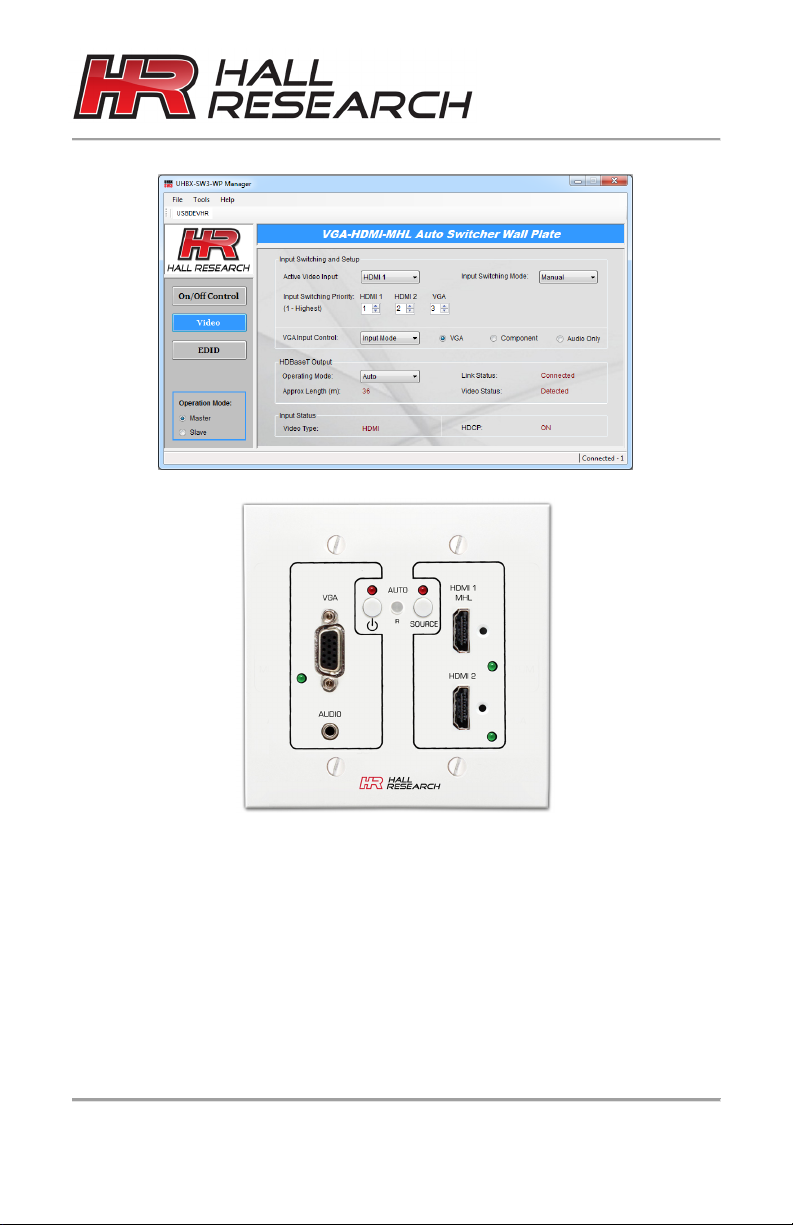
2.3.2 Video
All rights reserved.
Page 10

Software Guide
8
© Copyright 2015. Hall Research, Inc.
When the VGA input is configured for YPbPr (component
Active Video Input
The UHBX-SW3-WP has a total of three inputs : HDMI1, HDMI2, and VGA.
HDMI1 – This input can be used for either an HDMI or a MHL source.
HDMI2 – This input is only used for HDMI source.
VGA – This input can be configured as VGA, component, or audio only source.
Notice
video), Auto Source selection will not be able to detect the
source. So in this case you should not enable Auto Source
mode, and manually select inputs.
Similarly, when the VGA input is configured for Audio Only,
(can pass audio input with or without VGA connection),
then with just an audio connection (without video), the
device will not be able to automatically switch to that
input and it has to be selected manually.
Configuring the VGA input for YPbPr or Audio Only, also
will increase standby power consumption of the wall plate
and it will stay warm even if no input is connected.
Input Switching Mode
The UHBX-SW3-WP can select inputs either manually or automatically.
Manual – In this mode, each SOURCE button press will select the next input.
Auto – When the device is set in this mode, it will automatically switch to an input
with the highest priority as soon as it detects its presence.
All rights reserved.
Page 11

9
© Copyright 2015. Hall Research, Inc.
UHBX-SW3-WP
By default the Aspect Ratio is set for 16:9. This is because
Auto Lock - This is the auto mode as mentioned above with lock enabled, which is
locking the user from using the wall plate's SOURCE button to switch it out of Auto
and in to Manual mode.
Input Switching Priority
Each input can be independently set to any priority level from 1 to 3. Level 1 is the
highest priority, and level 3 is the lowest priority. If two inputs have the same priority
level, then they cannot interrupt one another (then they will act as first-come-first-serve).
VGA Input Control
The VGA Input Control has the following selections:
Auto Adjust – It is used to perform an auto adjust of the VGA input source on the
display (will try to best fit the video to the output screen).
Aspect Ratio – The VGA input source can have its aspect ratio set to either 4:3 or
16:9
Notice
most notebooks have a wide screen LCD. So when the user
duplicates their notebook's LCD to the VGA output and
connects it to the UHBX-SW3, eventually it winds up as a
widescreen 1080p HDMI signal on the display. So a 16:9
signal from the PC displayed as a 16:9 TV will have perfect
aspect ratio.
However, if the VGA source is a 4:3 format (such as 800x600
or 1024x768), to avoid stretching the width of the image
(thereby creating a flattened circle), you can select 4:3
aspect ratio in the GUI. This will instruct the scaler to put
black bars on the sides of the output signal to keep the video
shown on the HDTV as a 4:3 image.
All rights reserved.
Page 12

Software Guide
10
© Copyright 2015. Hall Research, Inc.
When used with the recommended UHBX-R-PSE receiver,
Brightness – The level of the VGA source brightness can be set between 0-100.
Color – The level of the VGA source color can be set between 0-100.
Contrast – The level of the VGA source contrast can be set between 0-100.
Input Mode – It is used to configure VGA input as VGA, component, or audio only.
Horizontal Flip – The VGA source can have its image displayed in normal or in
horizontal flip (good for teleprompting applications).
Output Scaling – The source at the VGA input can be set to either 720p or 1080p.
Vertical Flip – The VGA source can have its image displayed in normal or in vertical
flip.
Zoom – This is used to zoom out or zoom in the VGA input source on the display.
This is particularly useful if the VGA image's edges are cut off by the bezel of the
TV. For example if you don't see the Windows Start or Taskbar, you can zoom out
to try and get the edge on the screen.
HDBaseT Output
The operating mode of HDBaseT output can be set to either Auto or Long Reach mode.
Auto - When set to Auto, the HDBaseT output will follow the current mode on the
receiver. By default, it is the HDBaseT mode.
Long Reach - When set to Long Reach, the HDBaseT output will have the
strongest signal from the sender to the receiver. However, this mode does not
support deep color or 4K video.
Notice
leave the mode in Auto. It will then follow the mode set on
the Receiver.
The UHBX-R-PSE receiver has a Switch under the HDMI
output connector that can change its mode between
Standard and Long Reach modes.
HDBaseT-Lite receivers (70 meter/ Class B) do not support
Long Reach. So if you are using a receiver with Class B
HDBaseT, select Auto in GUI.
In addition to setting the HDBaseT operating mode, the GUI displays status such as link,
video, and approximate Cat6 cable length.
All rights reserved.
Page 13

11
© Copyright 2015. Hall Research, Inc.
UHBX-SW3-WP
Link – Connected or disconnected
Video – Detected or None
Approximate Length (m) – The cable length is measured in meters, and it is not
applicable when the connection is in Long Reach mode. The calculation may vary
according to cable quality.
Input Status
The UHBX-SW3-WP provides status of the detected video signal on the selected input.
Video Type – The type of video can be HDMI, DVI, MHL, or VGA
HDCP – It will be either on or off depending on presence of HDCP encryption on the
input.
2.3.3 EDID
The EDID table shown below is the current EDID the unit is passing to the source.
EDID mode can be set to either pass-thru or emulate.
Pass-thru (Default) – This is a default mode. When set to this mode, the EDID
passed to the source comes from a sink TV, LCD monitor, or projector connected to
an output.
Emulate – In this mode, the internal default EDID is passed to the source.
All rights reserved.
Page 14

Software Guide
12
© Copyright 2015. Hall Research, Inc.
2.4 Operation Mode
In a typical installation, the UHBX-SW3-WP is acting as the Master! This means that the
wall plate can switch between its 3 video inputs either automatically or manually.
Additionally the wall plate can also be programmed to send Power On/Off commands to
the remote display through the RS232 port of the remote receiver.
If RS-232 data is sent back from the display device to the wall plate, in Master mode, it is
ignored and no action is taken.
But what if you are planning to use a separate control system and want to control the
entire room's AV setup. In that case you can use the RS-232 port on the UHBX-R-PSE
Receiver to control the wall plate. All operational aspects of the wall plate can be
controlled if you put the wall plate in Slave operation mode. .
Master (Default)
can send programmed serial commands such as Power
On, Power Off, Volume UP, Volume Down, Mute On, and
Mute Off to a TV or a projector through UHBX-R-PSE, at
any specified baud rate from (1200-115,200). A typical
– In this mode, the UHBX-SW3-WP
All rights reserved.
Page 15

13
© Copyright 2015. Hall Research, Inc.
UHBX-SW3-WP
button press will trigger the unit to send any corresponding programmed serial
commands to the TV or the projector.
Slave – In this mode, the UHBX-SW3-WP can be controlled by another device
through the UHBX-R-PSE receiver. In this mode the baud rate is fixed at 9600. The
list of supported commands in Slave mode is shown in Appendix 1.
2.5. Tool Bar Menu
The UHBX-SW3-WP Manager toolbar consists of three main menus.
File
The File menu consists of the Exit selection as shown.
Exit – Exit the UHBX-SW3-WP Manager.
Tools
Load Configuration – Get an existing
configuration file from the PC. Configuration files
are text files that contain all user configurations
including power commands, communication
settings, auto off delay, input switching priorities,
etc.
Save Configuration – Save the current user
configuration as a file on PC.
Factory Default – Restore the device to factory default settings.
Firmware Update – Allow you to update any future device firmware.
Help
The Help menu has the About selection as shown.
About… - Display the current version of UHBX-SW3-WP
Manager, device firmware, USB serial number, and UI
firmware.
All rights reserved.
Page 16

Software Guide
14
© Copyright 2015. Hall Research, Inc.
2.6. Firmware Update
The firmware update can be found under the Tools menu. When the Firmware Update
is selected, the UHBX-SW3-WP Manager will open a Firmware Update window as
shown.
It is recommended to restart the GUI after the firmware update.
All rights reserved.
Page 17

15
© Copyright 2015. Hall Research, Inc.
UHBX-SW3-WP
Appendix 1 - Serial Commands in Slave Mode
Power:
Command: PWn <cr> Stands for Power On
Response: PWn <cr> Where n = 0 - 1 = Power Off - On
Auto Power:
Command: APn <cr> Stands for Auto Power
Response: APn <cr> Where n = 0 - 2 = Auto Power Off – On – On Lock
Input Select:
Command: ISn <cr> Stands for Input Select
Response: ISn <cr> Where n = 1 - 3 = HDMI1 - HDMI2 - VGA
Auto Input:
Command: AIn <cr> Stands for Auto Input
Response: AIn <cr> Where n = 0 - 2 = Auto Input Off – On – On Lock
Off Delay:
Command: ODn <cr> Stands for auto Off Delay
Response: ODn <cr> Where n = 0 - 60 (in minutes)
Switch Priority:
Command: SPn,m <cr> Stands for input Switching Priority
Query: SPn <cr>
Response: SPn,m <cr> Where n = 1 - 3 = HDMI1 - HDMI2 - VGA
(m = 1 - 3 (highest - lowest priority level)
Operation Mode:
Command: OMn <cr> Stands for Operation Mode
Response:
Low Power:
Command: LP <cr> Stands for Low Power
Response: LPn <cr> Where n = 0 -1 = Normal – Low Power
Mute:
Command: MTn <cr> Stands for Mute LED
Response: MTn <cr> Where n = 0 -1 = Off – On
OMn <cr> Where n = 0 - 1 = Master – Slave
All rights reserved.
Page 18

Software Guide
16
© Copyright 2015. Hall Research, Inc.
VGA Auto Adjust:
Command: AA <cr> Stands for VGA Auto Adjust
Response: AA <cr>
VGA Aspect Ratio:
Command: ARn <cr> Stands for VGA Aspect Ratio
Response: ARn <cr> Where n = 0 - 1 = (4:3) – (16:9)
VGA Brightness:
Command: BNn <cr> Stands for VGA Brightness
Response: BNn <cr> Where n = 0 -100
VGA Color:
Command: CLn <cr> Stands for VGA Color
Response: CLn <cr> Where n = 0 -100
VGA Contrast:
Command: CTn <cr> Stands for VGA Contrast
Response: CTn <cr> Where n = 0 -100
VGA Input Configure (Mode):
Command: ICn <cr> Stands for VGA Input Configure
Response: ICn <cr> Where n = 1 - 3 = VGA – Component – Audio only
VGA Left to Right (Horizontal Flip):
Command: LRn <cr> Stands for VGA Left to Right
Response: LRn <cr> Where n = 0 -1 = Normal - Reversed
VGA Output Scale:
Command: OSn <cr> Stands for VGA Output Scaling
Response: OSn <cr> Where n = 0 -1 = 720p – 1080p
VGA Top to Bottom (Vertical Flip):
Command: TBn <cr> Stands for VGA Top to Bottom
Response: TBn <cr> Where n = 0 -1 = Normal - Reversed
VGA Underscan (Zoom):
Command: USn <cr> Stands for VGA Underscan
Response: USn <cr> Where n = 1 - 6
All rights reserved.
Page 19

17
© Copyright 2015. Hall Research, Inc.
UHBX-SW3-WP
If n is not specified in any of the commands above, the
Notice
command becomes a query command instead of a set
command.
In response to a query command the system reports the
current status of that command.
Status Update:
Command: SU <cr> Stands for get full Status Update
Response: PWn <cr> APn <cr> ISn <cr> AIn <cr> ODn <cr> SPn,m <cr> ARn
<cr> BNn <cr> CLn <cr> CTn <cr> ICn <cr> LRn <cr> OSn <cr>
TBn <cr> USn <cr> FWx.x <cr>
Factory Default:
Command:
Response: FD <cr>
Firmware Version:
Command: FW <cr> Stands for Firmware Version
Response: FWx.x <cr> UHBX-SW3-WP Firmware Version
Button:
Command: BLn,m <cr> Stands for Aux keypad Button LED
Response: BLn,m <cr> Where n = 1 - 3 = PWR LED – MUTE LED
m = 0 - 1 = LED Off – LED On
Volume Up:
Response: UP <cr> Stands for Volume Up
Sent when user pushes the Volume Up button on Aux Kpd
Volume Down:
Response: DN <cr> Stands for Volume Down
Sent when user pushes the Volume Down button on Aux Kpd
Error Commands
ERR0 – UHBX-SW3-WP power is off.
ERR1 – Invalid command
ERR2 – The VGA scaler board is in low power mode
FD <cr> Stands for Factory Default
All rights reserved.
Page 20

© Copyright 2015. Hall Research, Inc.
All rights reserved.
 Loading...