

Page 1
H
R
aallll
H
eesseeaarrcchh
R
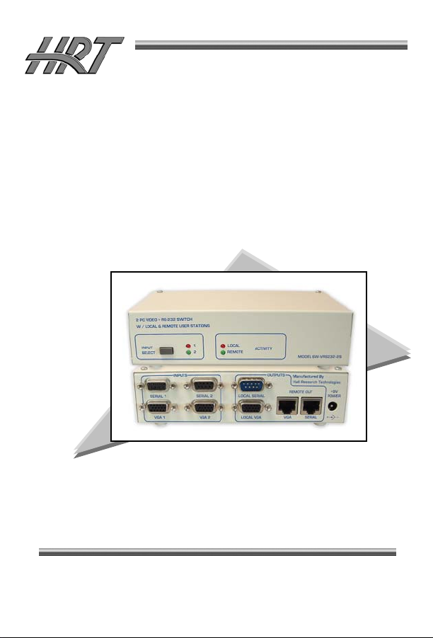
Model SW-VRS232-2
2-PC video and Serial Switch
With Local and Remote User Stations
T
eecchhnnoollooggiieess,, IInncc..
T
UMA1162 Rev. A
SUPPORT &
ORDERING
INFORMATION
For technical support, Call 714-641-6607 or fax 714-641-6698
Order by phone: toll-free in the U.S. 800-959-6439
Web site: www.hallresearch.com
Hall Research Technologies, 1163 Warner Ave. Tustin, CA 92780
Page 2

Page 3
Model SW-VRS232
TRADEMARKS USED IN THIS MANUAL
Hall Research, HRT, and are trademarks of Hall Research
Technologies Inc.
Any other trademarks mentioned in this manual are acknowledged to be the
property of the trademark owners.
FEDERAL COMMUNICATIONS COMMISSION
RADIO FREQUENCY INTERFERENCE
STATEMENT
This equipment generates, uses, and can radiate radio frequency energy and if
not installed and used properly, that is, in strict accordance with the
manufacturer’s instructions, may cause interference to radio communication. It
has been designed to comply with the limits for a Class A computing device in
accordance with the specifications in Subpart B of Part 15 of FCC rules, which
are designed to provide reasonable protection against such interference when
the equipment is operated in a commercial environment. Operation of this
equipment in a residential area is likely to cause interference, in which case the
user at there own expense will be required to take whatever measures may be
necessary to correct the interference. Changes or modifications not expressly
approved by the party responsible for compliance could void the user’s authority
to operate the equipment. This digital apparatus does not exceed the Class A
limits for radio noise emission from digital apparatus set out in the Radio
Interference Regulation of the Canadian Department of Communications.
1
Page 4

VGA –RS232 SWITCH AND EXTENDER
Contents
1. Introduction.............................................................................2
1.1 General.............................................................................2
1.2 Features ...........................................................................3
2. Installation...............................................................................4
2.1 Connecting the SW-VRS232-2S ......................................4
2.2 Connecting the SW-VRS232-2R......................................5
2.3 Mounting the SW-VRS232-2S..........................................6
3. Configuration and Operation...................................................9
3.1 Front Panel LED Indicators ..............................................9
3.2 Adjusting Remote video quality for long cables................9
3.3 UTP Cable Recommendations.......................................10
4. Troubleshooting....................................................................11
4.1 Contacting Hall Research Technologies ........................11
4.2 Shipping and Packaging.................................................11
5. Specifications........................................................................12
1. Introduction
1.1 General
This manual covers both sender (Model SW-VRS232-2S) and remote (Model
SW-VRS232-2R), available either separately, or as a set.
The Hall Research 2 input switch/extender is a powerful, yet simple 2x1 VGA
and RS-232 switch. It allows one or two users to select between 2 PC’s, and
access the selected PC’s Serial RS-232 port and VGA video. A typical
installation would be connecting a touch-screen LCD to the unit and then be
able to switch the touch-screen LCD between 2 PC’s.
2
Page 5

Model SW-VRS232
The local user can connect to the Sender unit. To add a remote user, an optional
2-gang wall plate would be needed. The optional wall plate connects to the local
unit via 2 Catx cables. No power supply is required for the wall plate. One Catx
cable is used to extend the Video and the other is used to extend bi-directional
RS-232. The Remote unit can be located up to 500ft. away from the Sender
Unit.
The user at the Sender station can switch between the 2 PC’s by simply pushing
a button on the unit’s front panel. LED indicators provide feedback as to which
PC input is selected.
The Remote station controls the same PC as the local (both displays show the
same image). Any RS-232 output from the PC is sent to both Stations, and RS232 data from each station is automatically multiplexed as a first-come-firstserved basis. This means that, for example, if the sender station is sending RS232 data to the selected PC, the RS-232 data from the Remote station is
ignored until the Sender station stops transmitting data for about a second. In
this way collision of Rx data is prevented.
If control of the input selection is needed at the remote station, an optional push
button switch cord can be utilized (Model PB-SW). This push button plugs into
the receiver wall plate and can sit by the remote LCD. It has a momentary button
with built-in LED. Every time the switch is pressed the input selection is toggled
between PC 1 and PC 2. The LED on the remote push button cord blinks once
when PC 1 is selected, and twice when PC 2 is selected. The push button is
only available in a 6ft. length, but can be easily extended since it uses a
standard 3.5mm mini-stereo type of plug.
1.2 Features
Supports High Resolutions up to UXGA (1600x1200)
Sender drives video and serial up to 500 ft.
Auto-detect serial activity allows only one user to control serial RS-232 at
a time.
Single switch operation from either local or remote stations
Only one power supply needed (power sent over Catx to receiver)
2-gang wall plate receiver and mountable sender for clean installation
Compact, Rugged, Reliable, and Economical
Made in USA
3
Page 6

VGA –RS232 SWITCH AND EXTENDER
2. Installation
2.1 Connecting the SW-VRS232-2S
Figure 2.1
1. For connection to a typical PC, use HD15 M/M cables for Video, and straightthrough DB9 M/F cables for RS-232. Connect all devices to the unit and then
connect the Power supply to the device.
Front
View
Rear
View
Figure 2.2 SW-VRS232-2S
4
Page 7

Model SW-VRS232
2.2 Connecting the SW-VRS232-2R
1. If the optional 2-gang wall plate receiver (Model SW-VRS232-2R) will be
used, make sure to plug the Catx cables to the correct connector on both ends.
The unit is designed so that there is no damage if the cables are cross
connected since the power distribution uses the same pins in the UTP cable, but
if plugged incorrectly, the system will not work.
Figure 2.3
SW-VRS232-2R
Receiver
PB-SW
2. The remote user can switch between PC’s by using an optional push-button
switch, (Model # PB-SW). When pushed, an LED in the switch will blink to
indicate which PC is selected – once for PC 1, twice for PC 2.
3. Video compensation is set with the receiver running, prior to installing the
wall plate. Adjustment is made via a small potentiometer on the back of the
video board, labeled “CABLE ADJ”. Start with the compensation pot turned fully
CCW (no compensation); then gradually increase until video image bleeding is
eliminated. See Section 3 for cable type and video considerations.
5
Page 8

VGA –RS232 SWITCH AND EXTENDER
The system is designed to work the touch-screen
LCD’s that use RS-232. USB touch-screens are not
supported even if an adapter is used.
When 2 stations are used (local and remote), you must
ensure that both touch-screens are exactly
make and model. This is because there is no software
or special driver used with this setup and the PC is not
aware that there are 2 touch-screens, therefore the
calibration of both LCD’s need to be identical.
To calibrate the touch-screen driver of each PC
(geometry targets), it is recommended to use the local
touch-screen. First select PC 1 and then enter the
calibration screen of PC 1 where you are required to
touch a few targets that are displayed on the screen.
Once PC 1 is calibrated, select PC 2 and repeat the
process. If the 2 touch-screen LCD’s are identical, then
the remote touch screen’s calibration should be
correct.
Note about Touch-Screen LCD’s
the same
2.3 Mounting the SW-VRS232-2S
The SW-VRS232-2S provides mounting keyholes to secure the unit for a clean
and simple installation.
To avoid risk of electric shock
where power or data lines may be present, such as
near electrical outlets, switches, or server rooms.
Always use safety glasses when working with power
tools.
1. Use the stencil sheet provided with the Sender to find an acceptable location
for the unit. Once correctly positioned, tape the stencil down to secure it.
Before you start:
, do not install screws
6
Page 9

Model SW-VRS232
2. Drill pilot holes where indicated on the stencil, using a 1/16” bit.
3. Screw Selection
the unit is being mounted to. It is recommended to use a 1” long, #6 screw
(shank = 0.138, or about 9/64”).
4. Remove the stencil and install screws, leaving 0.19” (about 3/16”) of the
threads protruding (when measuring, do not include the screw head).
Improper installation of mounting screws may result in
damage to unit. A screw protruding 0.40” (or more
than about 3/8”) will hit the circuit board, causing
possible damage. Additionally, the unit will not be
securely mounted, which may cause it to fall. Measure
screws for proper height prior to securing the unit.
: Be sure to use the appropriate kind of screw for the surface
CAUTION:
SW-VRS232-2S Bottom View of Keyhole Mounts
7
Page 10

VGA –RS232 SWITCH AND EXTENDER
Stencil - Top View with Dimensions (NOT TO SCALE)
Side View with Clearance Dimensions (NOT TO SCALE)
8
Page 11

Model SW-VRS232
3. Configuration and Operation
3.1 Front Panel LED Indicators
The SW-VRS232-2S has two sets of LED indicator lights. The Input Select
LEDs indicate which input is currently selected. The Activity LEDs light when
RS-232 data is being received, and indicate whether it is coming from the local
station or the remote.
3.2 Adjusting Remote video quality for long
cables
The video quality at the remote station depends on: (1) the length of the Cat5
cable, (2) video resolution setting, and (3) refresh rate setting.
In general, at low and mid resolutions, excellent image reproduction is provided
at up to 500 feet. At high resolution and refresh rates perfect image reproduction
can be achieved at shorter distances (see table below). Using longer cables or
higher resolution rates will still produce an image, but the reproduction quality
will be reduced.
Maximum Recommended Cable Lengths
Table 3.1
Refresh Rate
60 Hz 75 Hz 85 Hz
800x600 500 ft 500 ft 500 ft
1024x768 500 ft 450 ft 400 ft
1280x1024 400 ft 350 ft 300 ft
Resolution
1600x1200 300 ft 300 ft 300 ft
9
Page 12

VGA –RS232 SWITCH AND EXTENDER
3.3 UTP Cable Recommendations
RED
RED
UTP cables have 4 twisted pairs inside. The video transmission over UTP uses
3 individual pairs for each color (Red, Green, & Blue). As shown in figure 3.2
above, a characteristic of Category-5/5e/6 cable is that the pairs of wires are
twisted at different rates. Therefore, for a given length of Cat-5 cable the total
length of a particular pair could be longer than others. Since the signals travel in
the cable at a fixed speed, the arrival times of signals can be skewed in a long
cable (those that have to travel farther arrive later and the corresponding color
shifts to the right).
This is seen on the monitor as separation, or lack of convergence in colors. For
example a vertical white line on the screen may look to have a red tinge on the
left edge and blue tinge on the right edge.
This effect gets worse at high resolutions, high refresh rates, long cables (in
excess of 200 feet), and depends on the cable construction itself. Hall Research
highly recommends the use of UTP cables specifically constructed for video
transmission. In these cables the all the twisted pairs are the same length. They
are available from several sources including Hall Research (part numbers
shown below).
Zero-Skew CAT5 Cable for use with Hall Research CAT5 Products
PART NUMBER
CUTP-Z-1000-BLK 1000 ft.
Zero-Skew CAT5 cable. Bulk spool of 1000 ft
CUTP-ZP-1000-BLK 1000 ft.
Zero-Skew CAT5 cable. Bulk spool of 1000 ft Plenum Rated
If you are going to use commercial grade UTP cable, then we recommend using
Cat5 or Cat5e rather than Cat6, since the twist ratio match is better in Cat5
cable.
Figure 3.2
BLUE
10
Page 13

Model SW-VRS232
4. Troubleshooting
Most common problems are caused by the following:
• Using different models of Touch-Screen monitors
• Crossed Cat5 cables.
• Using a Cat5 cable that is too long, not straight through, or not
terminated properly
• Display device does not support the resolution that is being sent (in
which case you should check operation without the extender first)
4.1 Contacting Hall Research Technologies
If you determine that your switch is malfunctioning, do not attempt to repair the
unit. There are no user serviceable parts inside the unit. Opening the unit will
void the warranty. Contact HRT’s Tech. Support at 714-641-6607 to obtain an
RMA (Return Authorization) number.
Before you do, make a record of the history of the problem. We will be able to
provide more efficient and accurate assistance if you have a complete
description
4.2 Shipping and Packaging
If you need to transport or ship your device:
.
• Package it carefully. We recommend that you use the original container if
possible.
• Before you ship the units back to Hall Research Technologies for repair or
return, contact us to get a Return Authorization (RMA) number.
11
Page 14

VGA –RS232 SWITCH AND EXTENDER
5. Specifications
Standards Analog VGA Video (RGBHV), YPbPr, or RGB
Resolutions All up to UXGA (1600x1200 / 60Hz), 1080p
Video Level 0.7 v p-p on RGB, 5v p-p H/V sync
Bandwidth 20 Hz to 450 MHz
Common Mode
Noise Rejection 100 dB @ 60 Hz, 70 dB @ 1 MHz, 50 db @ 10 MHz
Max Distance Up to 500 ft. (152 meters) - See table 3.1 for details
Temperature Operating: 32 to 122 Deg F (0 to 50 Deg C);
Storage: -40 to +185 Deg F (-40 to +85 Deg C)
Enclosure Steel
MTBF 100,000 hours (calculated estimate)
Power Via the included power adapter. Voltage: 9v DC
Size (H x W x D) Sender: 2.81” x 6.5” x 3.75”
Receiver: 4.56” x 4.56” x 1.25”
Sender has three mounting keyholes; see mounting
signals with sync-on-green.
Center-Positive. Average Power Consumption:
250mA (Sender) 250mA (Receiver)
section for details.
12
Page 15

Page 16

© Copyright 2009. Hall Research Technologies,
Inc.
All rights reserved.
1163 Warner Ave., Tustin, CA 92780
Ph: (714)641-6607, Fax: (714)641-6698
 Loading...