

Page 1
H
R
aallll
H
eesseeaarrcchh
R
T
eecchhnnoollooggiieess,, IInncc..
T
VGA-to-DVI Video Scaler
Converts and Scales Analog VGA or HDTV Component to DVI
Digital or Analog DVI output can be set to various PC or HDTV Resolutions!
INFORMATION
CUSTOMER
SUPPORT
Order toll-free in the U.S. 800-959-6439
FREE technical support, Call 714-641-6607 or fax 714-641-6698
Mail order: Hall Research Technologies, 1163 Warner Ave., Tustin, CA 92780
Web site: www.hallresearch.com • E-mail: info@ hallresearch.com
UMA1062 Rev. D
Page 2

Page 3

VGA - to - DVI Video Scaler
TRADEMARKS USED IN THIS MANUAL
Hall Research, HRT, and (logo) are trademarks of Hall Research
Technologies, Inc. IBM are a registered trademark of International Business
Machines Corporation.
Any other trademarks mentioned in this manual are acknowledged to be the
property of the trademark owners.
FEDERAL COMMUNICATIONS COMMISSION
RADIO FREQUENCY INTERFERENCE STATEMENT
This equipment generates, uses, and can radiate radio frequency energy and
if not installed and used properly, that is, in strict accordance with the
manufacturer’s instructions, may cause interference to radio
communication. It has been designed to comply with the limits for a Class
A computing device in accordance with the specifications in Subpart B of
Part 15 of FCC rules, which are intended to provide reasonable protection
against such interference when the equipment is operated in a commercial
environment. Operation of this equipment in a residential area is likely to
cause interference, in which case the user at their own expense will be
required to take whatever measures may be necessary to correct the
interference.
Changes or modifications not expressly approved by the party responsible
for compliance could void the user’s authority to operate the equipment.
1
Page 4

Model SC-VD-2
Table of Contents
1. Introduction .............................................................................................. 3
1.1 General................................................................................................ 3
1.2 Features............................................................................................... 4
2. Installation ................................................................................................ 4
2.1 Input connection ................................................................................. 4
2.2 Output connection............................................................................... 5
2.3 Connection Block Diagrams............................................................... 5
3. Configuration & Operation....................................................................... 6
3.1 Front and Rear Panels.........................................................................6
3.2 Menus and Adjustments ..................................................................... 6
4. Troubleshooting........................................................................................ 9
Contacting Hall Research Technologies...................................................9
Shipping and Packaging ........................................................................... 9
5. Specifications............................................................................................ 9
Input Resolutions.................................................................................... 10
Output Resolutions ................................................................................. 10
Reference Information............................................................................ 10
Hall Research Technologies, Inc.
Home of the Mini-Cat®
2
Page 5
VGA - to - DVI Video Scaler
1. Introduction
1.1 General
The SC-VD-2 is a high performance
PC/HDTV scaler that accepts analog RGB
inputs (VGA or Component) and converts it
to DVI-I (digital + analog) output.
The input to the SC-VD-2 is analog PC or
HDTV signal (RGBHV, YPbPr, or YCbCr).
The output of the SC-VD-2 is digital +
analog PC or HDTV DVI signal with a format of digital RGBHV bit-stream
plus analog RGBHV, known as DVI-I (Integrated digital and analog).
The input resolution is automatically detected while the output resolution
and refresh rate can be selected through OSD menu and front panel push
buttons.
DVI output enables an all digital rendering of video without the losses
associated with an analog interface and is ideal for use with digital displays
such as LCD, plasma or DLP projectors.
The SC-VD-2 Video Processor combines the functions of a video scaler,
scan-converter, and format transformer and is packed into a compact and
durable metal housing with easy-to-use touch buttons.
The controls include input/output setup picture adjustment, H/V phase
adjustment, System information and many other advanced options.
The SC-VD-2 allows you to specify a resolution and refresh rate for its
output. Then it will output a steady (uninterrupted) DVI signal to your
display device at your specified rate regardless of the input. This effectively
allows any VGA switch, such as HRT's VS-2 or VS-4, to become a
seamless switch with DVI output option. The output timing is constant
regardless of what is happening at the input. So when you switch from one
input to another, the display device does not see any interruption in the
signal coming to it.
3
Page 6

Model SC-VD-2
1.2 Features
• Converts analog VGA from any PC (or component from any DVD
player) to Digital DVI output.
• Ideal for use with digital displays such as LCD, plasma, or DLP
projectors.
• Digital output reduces losses associated with analog signals.
• The resolution of any PC or HDTV video signal can be scaled up or
scaled down to any other PC or HDTV resolution. It can also change the
frame rate of the output.
• 50 MB Video memory for real-time frame rate conversion.
• Signal format conversion between RGBHV and YPbPr.
• Input: PC(VGA/SVGA/XGA/SXGA) + HDTV(480i 576i 480p 567p
720p 1080i), @ 60 to 85 Hz
• Output: PC
• Automatically detects input mode and timing parameters
• Allows fine-tuning the output picture to optimum through adjustment of
sampling clock, phase, and position on screen.
• Easy- to- use push buttons and OSD menu control.
(VGA/SVGA/XGA/SXGA) + HDTV(480p/576p/720p/1080i)
2. Installation
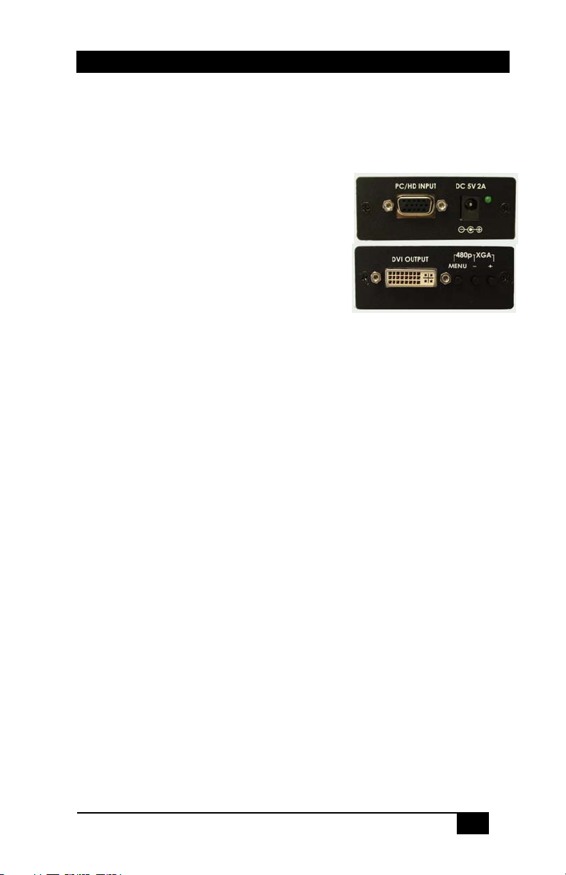
2.1 Input connection
The SC-VD-2 can accept both PC and HDTV inputs. When accepting a PC
input use the 15-pin D-sub cable to connect the output of a PC device to the
input connector labeled PC/HDTV on the back of SC-VD-2.
When accepting a HDTV input use a15-pin D-sub to YPbPr/3 RCA cable
to connect the YPbPr output (or YCbCr) of a HDTV device to the
PC/HDTV input connector of the SC-VD-2.
The SC-VD-2 can automatically detect the mode and resolution of the
PC/HDTV input (The mode can also be forced via OSD menu).
4
Page 7

VGA - to - DVI Video Scaler
2.2 Output connection
The SC-VD-2 can output a variety of PC resolutions and HDTV
progressive resolutions, in both digital and analog format.
To use the SC-VD-2's digital output select DVI-D in the Output Setup of
the menu, and use a DVI cable to connect the DVI output of the SC-VD-2
to the DVI input of a display monitor, or HDTV device.
To use analog output of the SC-VD-2, select DVI-A in the Output Setup of
the menu, and use the DVI to VGA adaptor or cable to translate the analog
outputs in the DVI connector into VGA configuration to connect to a VGA
monitor or to connect to the YPbPr input of a HDTV device through a
VGA to YPbPr/3RCA adaptor cable.
2.3 Connection Block Diagrams
In the above diagrams the output of the SC-VD-2 is set to digital DVI. If
you set the output to Analog DVI, you can use an analog LCD monitor and
or HDTV; however you will need adapters or cables for connection to the
unit.
5
Page 8

Model SC-VD-2
3. Configuration & Operation
3.1 Front and Rear Panels
3.2 Menus and Adjustments
Pressing the Menu button will bring up the OSD menu controls on the
screen as follows:
¾ Input set up
¾ Output set up
¾ Picture Adjust
¾ HV Adjust
¾ OSD Adjust
¾ System Information
¾ Auto Adjust
¾ Exit
Use + or - to move the arrow cursor to your desired selection, then press
MENU to confirm your selection and enter into that sub menu.
When selected, a sub menu of clock, phase, and input
IInnppuutt sseett uupp -
mode is shown.
YPBPR …
Use + or - to choose the parameter your want to adjust and then press Menu
(Enter) to highlight your selection. Once a parameter is high-lighted use +
or - to increase or decrease the setting value. Press Menu (Enter) again to
leave the setting. Move the arrow to exit then press Menu/Enter to Exit.
Clock: Used to adjust for optimal input clock frequency for a stable picture.
Pressing + narrows the width of the picture toward the left. Pressing extends the width of the picture toward the right.
6
-
9 RGB
Page 9

VGA - to - DVI Video Scaler
Phase: Used to adjust for lowest noise of the picture (edge tearing).
YPbPr RGB: The SC-VD-2 automatically detects and shows the input
format as YPbPr or RGB. However, you can manually select the YPbPr or
RGB to match the format of your input. Selecting a format that doesn't
coincide with your input will result in an abnormal picture.
When selected, a sub-menu appears for the DVI
OOuuttppuutt sseett uupp -
-
output format (analog or digital) and Output Mode (refresh-rate and
resolution).
Output Modes (Under DVI-D, YPbPr outputs are not available)
PC Resolutions HDTV Resolutions
VGA 640 X 480@60/72/75/85Hz 1080i-RGB 1920 X1080@60Hz
VGA 70 720 X 400@70Hz 720p-RGB 1280X 720@60Hz
VESA 85 640 X 400@85Hz 576p-RGB 720X 576@60Hz
SVGA 800 X 600@60/72/75/85Hz 480p-RGB 720 X 480@60Hz
XGA 1024 X 768@60/70/75/85Hz 1080i-YPbPr 1920 X1080@60Hz
Mac 1152 X 864@ 70/75Hz 720p-YPbPr 1280 X 720@60Hz
WXGA 1280 X 768@60Hz 576p-YPbPr 720 X 576@60Hz
1280A 1280 X 960@60Hz 480p-YPbPr 720 X 480@60Hz
SXGA 1280 X 1024@60/75Hz
When selected the following adjust parameters will
PPiiccttuurree AAddjjuusstt -
-
appear:
The factory preset values are shown above
Select reset to reset all adjustment back to the factory preset values.
7
Page 10

Model SC-VD-2
HHVV aaddjjuusstt -
When selected the following sub-menu appears.
-
Use + - to adjust the best horizontal and vertical position of the picture.
When selected, you can adjust the Horizontal and
OOSSDD aaddjjuusstt -
Vertical position of the OSD menu.
-
SSyysstteemm iinnffoorrmmaattiioonn -
resolutions and their vertical refresh rates on the screen.
When selected the SC-VD-2 will automatically adjust all
AAuuttoo aaddjjuusstt -
the parameter to the factory preset value.
Select to exit from the current menu page.
-
EExxiitt -
-
When selected, it shows the input/output
-
Notes
The default output resolution is XGA @ 60Hz.
The unit has non-volatile memory. It saves all your settings before
power off, and recalls those settings on next power on.
Quickly Jumping to XGA or 480p Output
At any time, pressing + and - buttons simultaneously for a few seconds will
reset the output resolution to XGA@60Hz, and other settings back to
factory default values. Pressing the Menu and – together for a few seconds
will choose 480P output mode.
8
Page 11

VGA - to - DVI Video Scaler
4. Troubleshooting
There are no field serviceable parts or circuits in the device. If you think
that the device is malfunctioning (or you have no picture output), please
first try to reset to factory default settings by pressing the “+” and “-”
buttons (or “menu” and “-” buttons) simultaneously for 2 seconds (See
above).
Contacting Hall Research Technologies
If you determine that your scaler is malfunctioning, do not attempt to repair
the unit. Contact HRT’s Tech. Support at 714-641-6607.
Before you do, make a record of the history of the problem. We will be able
to provide more efficient and accurate assistance if you have a complete
description.
Shipping and Packaging
If you need to transport or ship your Video Processor:
• Package it carefully. We recommend that you use the original
container.
• Before you ship the units back to Hall Research Technologies for
repair or return, contact us to get a Return Authorization (RMA)
number.
5. Specifications
General
Input Format: Analog RGBHV, YPbPr, YCbCr
Input Signal: RGB: 0.7Vp-p, 75 ohm, HV: 3 to 5 Vp-p TTL
Y: 1 Vp-p 75 ohm; PbPr: 0.7 Vp-p 75 ohm
Input Connector: HD-15 Female VGA
Output Format: Digital RGBHV or Analog RGBHV or Analog YPbPr
Output Connector: 29-pin DVI-I
Power: 5V DC at 2 A max (Universal power supply included)
9
Page 12

Model SC-VD-2
e
e
Input Resolutions
PC Resolutions HDTV Resolutions
VGA 640 X 480@60/72/75/85Hz 1080i 1920 X1080@60Hz
VGA 70 720 X 400@70Hz 720p 1280X 720@60Hz
VESA 85 640 X 400@85Hz 576p 720X 576@50Hz
SVGA 800 X 600@60/72/75/85Hz 576i 720X 576@50Hz
XGA 1024 X 768@60/70/75/85Hz 480p 720 X 480@60Hz
Mac 1152 X 864@ 70/75Hz 480i 720 X 480@60Hz
WXGA 1280 X 768@60Hz
1280A 1280 X 960@60Hz
SXGA 1280 X 1024@60/75Hz
Output Resolutions (Under DVI-D, YPbPr outputs are not available)
PC Resolutions HDTV Resolutions
VGA 640 X 480@60/72/75/85Hz 1080i-RGB 1920 X1080@60Hz
VGA 70 720 X 400@70Hz 720p-RGB 1280X 720@60Hz
VESA 85 640 X 400@85Hz 576p-RGB 720X 576@60Hz
SVGA 800 X 600@60/72/75/85Hz 480p-RGB 720 X 480@60Hz
XGA 1024 X 768@60/70/75/85Hz 1080i-YPbPr 1920 X1080@60Hz
Mac 1152 X 864@ 70/75Hz 720p-YPbPr 1280 X 720@60Hz
WXGA 1280 X 768@60Hz 576p-YPbPr 720 X 576@60Hz
1280A 1280 X 960@60Hz 480p-YPbPr 720 X 480@60Hz
SXGA 1280 X 1024@60/75Hz
Reference Information
DVI Connector pinout N/U = Not Used
Pin Signal nam
1 TMDS Data2– 13 TMDS Data3+ (N/U)
2 TMDS Data2+ 14 +5V Power
3 TMDS Data2/4 Shield 15 Ground for +5V Power
4 TMDS Data4– (N/U) 16 Hot Plug Detect
5 TMDS Data4+ (N/U) 17 TMDS Data0–
6 DDC Clock 18 TMDS Data0+
7 DDC Data 19 TMDS Data0/5 Shield
8 Analog vertical sync 20 TMDS Data5– (N/U)
9 TMDS Data1– 21 TMDS Data5+ (N/U)
10 TMDS Data1+ 22 TMDS Clock Shield
11 TMDS Data1/3 Shield 23 TMDS Clock+
12 TMDS Data3– (N/U) 24 TMDS Clock–
C1 Analog red C4 Analog horizontal sync
C2 Analog green C5 Analog ground
C3 Analog blue
Pin Signal nam
10
Page 13

VGA - to - DVI Video Scaler
11
Page 14

Model SC-VD-2
12
Page 15

Page 16

The difference between a “good” installation and a “great” one! ™
Products Designed and Made in the USA
© Copyright 2008. Hall Research Technologies, Inc.
All rights reserved.
1163 Warner Ave., Tustin, CA 92780
Ph: (714)641-6607, Fax: (714)641-6698
 Loading...