

Page 1
SUPPORT &
ORDERING
INFORMATION
SC-1080D
Multi-format PC/HD Video Scaler
For technical support, Call 714-641-6607 or fax 714-641-6698
Order by phone: toll-free in the U.S. 800-959-6439
Web site: www.hallresearch.com
Hall Research, 1163 Warner Ave. Tustin, CA 92780
UMA1154 Rev. E
Page 2

Page 3

Model SC-1080D
1
TRADEMARKS USED IN THIS MANUAL
Hall Research, HR, and its logo are trademarks of Hall Research Inc.
Any other trademarks mentioned in this manual are acknowledged to be the
property of the trademark owners.
FEDERAL COMMUNICATIONS COMMISSIO N
RADIO FREQUENCY INTERFERENCE STATEMENT
This equipment generates, uses, and can radiate radio frequency energy and if
not installed and used properly, that is, in strict accorda nce with the
manufacturer’s instructions, may cause interference to radio communication. It
has been designed to comply with the limits for a Class A computing device in
accordance with the specifications in Subpart B of Part 15 of FCC rules, which
are designed to provide reasonable protection against such interference when the
equipment is operated in a commercial environment. Operation of this
equipment in a residential area is likely to cause interference, in which case the
user at there own expense will be required to take whatever measures may be
necessary to correct the interference.
Changes or modifications not expressly approved by the party responsible for
compliance could void the user’s authority to operate the equipment.
This digital apparatus does not exceed the Class A limits for radio noise
emission from digital apparatus set out in the Radio Interference Regulation of
the Canadian Department of Communications.
Page 4

2
Multi-format PC/HD Video Scaler
Contents
1. Introduction ...................................................................................................... 3
1.1 General ....................................................................................................... 3
1.2 Features ...................................................................................................... 4
2. Installation ....................................................................................................... 5
2.1 Connect ing the Video Inputs and Outputs .................................................. 5
2.2 Other Connections ...................................................................................... 7
3. Configuration and Operation ............................................................................ 8
3.1 Front Panel ................................................................................................. 8
3.2 OSD Me nus .............................................................................................. 10
3.3 Infra-Red Remote control (IR Remote) .................................................... 12
3.4 IR Codes .................................................................................................. 13
4. Serial Control ................................................................................................. 13
4.1 Read Commands ...................................................................................... 13
4.2 Key Commands ........................................................................................ 14
4.3 Set Commands ......................................................................................... 14
5. Troubleshooting ............................................................................................. 15
5.1 Contacting Hall Research ......................................................................... 15
5.2 Shipping and Packaging ........................................................................... 15
6. Specifications ................................................................................................. 16
Hall Research Inc.
Home of the Mini-Cat®
Page 5
Model SC-1080D
3
1. Introduction
†
1.1 General
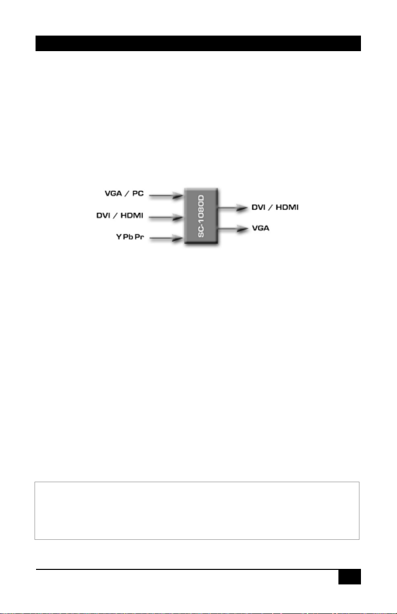
The SC-1080D is a member of Hall Research’s powerful video processor and
scaling product line. It combines the functions of many products in one compact
and versatile unit. It has both high definition analog as well as digital inputs.
Two outputs are available (simultaneously active†), one analog (RGBHV), and
one digital DVI-D (HDMI™ compatible).
Figure 1 – Block Diagram
The user can select the desired input using individual buttons on the front p anel,
on the included IR-remote, or by issuing ASCII RS232 commands.
The output resolution can range between 480i to 1080p for HDTV or VGA
(640x480) to WUXGA (1920x1200) for the PC. The unit uses the latest highresolution video scaling techniques to produce a superior video output for a crisp
image on the output display. Both video outputs can also be mirrored
horizontally making it ideal for teleprompting and rear projection systems where
the image needs to be flipped.
The desired output resolution is set directly using individual buttons on the IR
remote, or via unique ASCII RS232 commands. The front panel can also be
used to set the output resolution. A user-friendly on-screen-display (OSD) is
used to control the operation of the device from the front panel. There are also
‘hot-key’ combinations on the front panel to directly set the output to basic PC
or HDTV resolutions so that a picture can be displayed on any LCD.
For HDMI™ compliance, when the DVI input is selected, and HDCP content protection is
detected o n the signal, the HD15 analog output is blanked. The front panel input LED will
blink when this condition is detected. The Digital DVI output will be active when connected to
a HDCP compliant LCD (such as a display with HDMI™ input).
Page 6
4
Multi-format PC/HD Video Scaler
DVI
(1)
VGA (RGBHV)
(1)
The DVI input is HDCP compliant. This allows the unit to be used as an
HDMI™ Video Scaler (HDMI™ audio is not passed through). When the digital
input has HDCP encryption, the DVI output must be connected to a HDCP
compatible LCD (by definition all displays with HDMI™ input must be HDCP
compliant).
Built-in universal power supply keeps the installations clutter free.
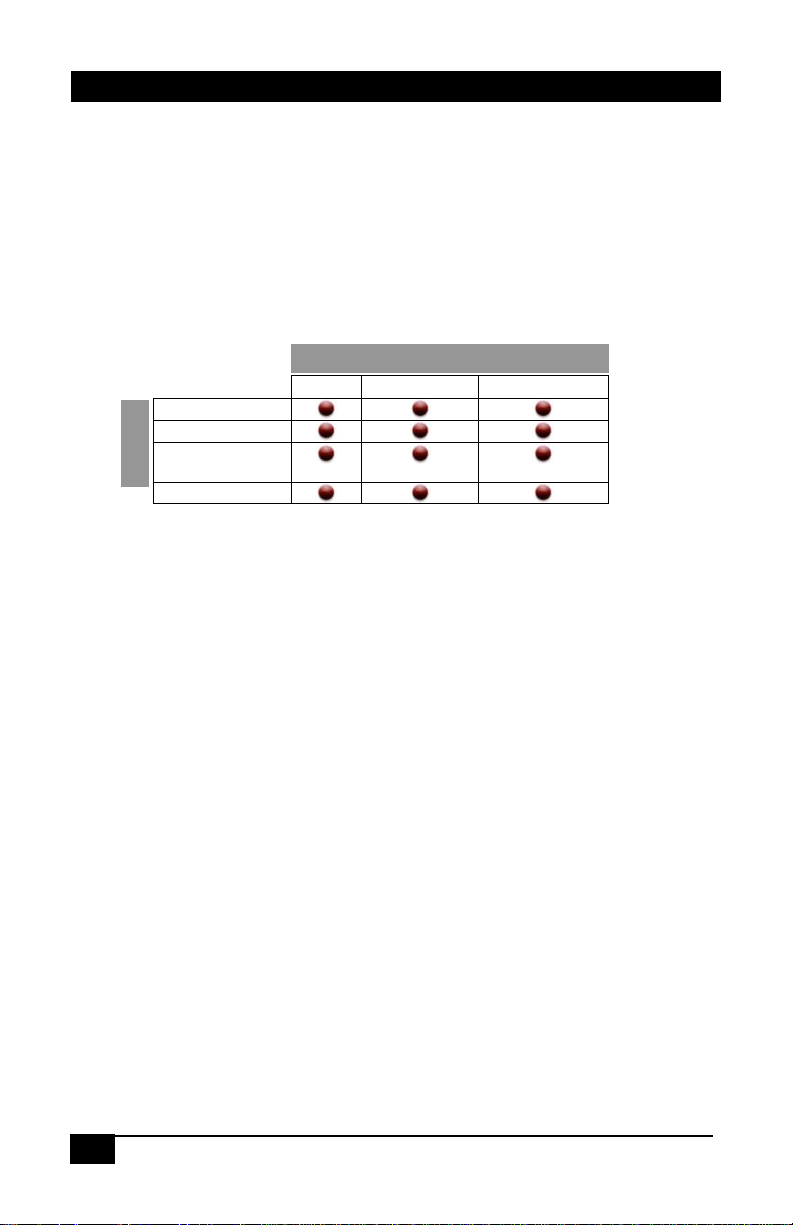
The unit can b e used to convert and change resolution in the following ways:
DVI
T
T
HDMI
U
U
P
P
YPbPr
N
N
I
I
(Component)
VGA (RGBHV)
Notes: (1) HDMI™ to DVI cable or adapter required
OOUUTTPPUUTT
HDMI
1.2 Features
High definition digital (DVI / HDMI) and analog (PC VGA / YPbPr)
Scaler that accepts PC RGB (up to UXGA), HD Component (480i up to
1080p) and DVI (up to WUXGA) and scales them to DVI and analog
outputs at user specified resolutions
HDCP (HDMI™) compliant DVI input and output
Output resolution selectable from 480i to 1080p (HDTV) and VGA to
WUXGA (PC).
RS232 Control port, IR remote, and Front Panel Controls
Native output mode ensures optimal resolution on the screen based on the
display’s EDID.
Output picture adjustments for brightness, contrast, RGB levels
Output can be mirrored! Perfect for teleprompting or rear projection
applications
State of the art scaling engine for sharp and fl icker free output
Built-in Universal Power Supply with standard IEC-320 jack
Compact, Rugged, Reliable, and Economical
Rack-mount brackets available
Page 7

Model SC-1080D
5
2. Installation
2.1 Connecting the Video Inputs and Outputs
The video scaler can accept a VGA (analog RGBHV from PC), DVI (digital
video from PC or HDMI™ source), and Component Video (Y Pb Pr) from any
source.
When the sourc e is from an HDMI™ output, an HDMI to DVI cable or adapter
is required. Please contact Hall Research if yo u need to purchase this cable.
Two outputs connectors are provided. Both show the selected input at the
desired output resolution.
Figure 2 - Rear Panel
Video cables for connecting the I/O ports are not supplied with the unit.
If you would like to mount the unit in a rack, please contact Hall Research to
purchase a rack-mount accessory kit for the uni t.
Figure 3 – Optional Rack-mount Kit
Page 8

6
Multi-format PC/HD Video Scaler
Video Inputs
Y Pb Pr: This is also known as Component Video input (analog) and on some
equipment it may be labeled as YCbCr. Since this input supports all interlace
and progressive resolutions from 480i to 1080p, you can connect it to both
legacy and new equipment alike as long as it has component video output. For a
list of supported resolutions, please see Spec ifications Section titled “Supported
Input Formats” found later in this manual . For example; if you are us i ng the DVI
output of the sc aler to connect to the HDMI input of an HDT V, you could use
the YPbPr input to connect your legacy DVD player, or PlayStation™
equipment to your HDTV.
VGA: This is the analog RGBHV s i gnal from a PC. A wide ra nge of resolutions
from VGA to WUXGA is supported. For a list of supported resolutions, please
see Specifications Section titled “Supported Input Formats” found later in this
manual. This input provides a convenient way to display your PC’s video
without losing clarity on any TV or HDTV as long as the TV has either HDMI™
or component inputs. Since the S C -108 0 D uses state of the art video scaling,
often you will achieve a sharper image on your LCD even if it has a VGA input!
DVI: This is the digital input to the Scaler. You can connect to the DVI-D or
DVI-I outputs of any PC. The DVI input of the unit supports HDCP encryption.
This means that it is compatible with Content Protected HDMI™ video sources.
However, the audio of HDMI source is not processed through and you should
configure and use the separate audio output of your HDMI™ source. The DVI
input of the scaler can handle most HDTV and PC resolutions. For a list, please
see Specifications Section titled “Supported Input Formats” found later in this
manual.
If you will be connecting to an HDMI™ sourc e you will ei t her need an
HDMI to DVI cable or an HDMI to DVI adapter.
If you will be connecting to a DVI source you will then need a male
to male DVI cable. DV I-D cables will work since they do not have the
extra pins that DVI-I cables have, but since the SC-1080D utilizes a
connector with all the pin positions you could use a DVI-I c abl e as
long as your source also has all t he pi n pos i tions.
Note about DVI input Cable
Figure 4
Example of HDMI™ to DVI Cable
Page 9

Model SC-1080D
7
Scaler
Interconnect Cable DB9 M/F
Remote Controller
PIN
Definition
PIN
Definition
2
TxD
2
RxD
3
RxD
3
TxD
5
GND
5
GND
Video Outputs
VGA: The output resolution will be a PC compatible (VGA to WUXGA)
RGBHV
signal.
Note about HDCP
For HDMI™ complianc e, if the input is from an HDMI™ source with content
protection, the VGA out put i s blanked and front panel LED blinks.
DVI: This is the TMDS digital output of the Scaler. You can connect this to any
PC compatible LCD with a DVI compatible connector input, or any HDTV with
a HDMI™ compatible connector input using the appropriate cable.
2.2 Other Connections
RS232: This 9-pin D-sub connector is for connecting to your PC or other s erial
control device for remote control of the SC-1080D.
AC power jack: This is a standard IEC320 / C14 power connection. The unit’s
power supply is universal (90 ~ 264 VAC, 50 ~ 60 Hz).
Page 10

8
Multi-format PC/HD Video Scaler
Figure 5 –
Front Panel
1 2 3 5 4
3. Configuration and Operation
3.1 Front Panel
1. Power: Press this button to turn ON or turn OFF ( standby) the power to
the unit.
2. Menu/Enter: This button serves two purposes.
A. Pressing the button will bring up the OSD main menu as shown in
the "OSD Menus" section of this manual.
B. To act as an "Enter" key to enter sub menu or to adjust setting value
of the selected parameter.
3. ▲ or ▼ buttons: The buttons provide 3 functions:
A. Input Select (▲): Press the ▲ button repeatedly to select your
desired input source. T he input sources are toggled through in the
following sequence.
B. Auto Tune ( ▼): Press the ▼ button to initiate picture a uto a djust for
analog inputs (component or PC/VGA). The scaler will fine tune the
position (centering) and color of the output picture.
Figure 6
Input Selection Sequence
Page 11

Model SC-1080D
9
C. When in the OSD menu mode: Press the ▲ or ▼ buttons to move
up or down the highli ghted bar to the desired parameter. Once a
parameter is highlighted then press the MENU / Enter button to adjust
the setting.
4. Input LED Indicators: The illuminated LED indicates that
corresponding source is being selected as input.
5. IR Sensor: Infrared remote control sensor.
Front Panel Quick Selection “Hot Keys”
Figure 7
If you are not getting any image on your display, it could be that the output
resolution setting of the SC-1080D is not supported by your LCD. Using serial
commands or the IR remo te, o ne can quickly switch between various output
resolutions. However since the front panel operation relies on OSD menu for
navigation, it is very difficult to change the output setting from the front panel if
you cannot see the OSD. Therefore to quickly jump to a basic resolution that is
supported by virtually all displays, is a great feature.
If you press and
get a XGA output which is supported by most PC compatible displays.
If you press and
get a 480p output which is supported by most HDTV compatible displa ys.
hold down
hold down
the MENU butt on, and then hit the ▲ button you
the MENU butt on, and then hit the ▼ button you
Page 12

10
Multi-format PC/HD Video Scaler
User
Movie
Overscan
Off
OSD Menu System
Video
Color
Output
OSD
Info
Contrast
User
VGA
Native
H. Position
Version
3.2 OSD Menus
Pressing the "MENU" button brings up the On-Screen Display (OSD) main
menu as shown below:
Brightness
Hue
Saturation
Sharpness
Picture Mode
Scale
Mirror
Noise
Reduction
(H Position)
(V Position)
Exit
†
†
Normal
Warm
Cool
SVGA
XGA
SXGA
UXGA
WXGA
WSXGA
WUXGA
480i
480p
576i
576p
720p (50/60)
V. Position
Timeout
Background
Exit
1080i (50/60)
1080p (50/60)
† H and V Position are only available for VGA or component input
Use the▲ or ▼ buttons to move the highlight bar to the desired parameter, and
then press the MENU button to enter the sub-menu of the selected parameter.
Video Submenu:
Contrast
Figure 3
OSD Main Menu structure
Brightness
Hue
Saturation
Picture Mode
Scale
Mirror
Noise Reduction
(H Position)
(V Position)
Exit
Standard
Vivid
Underscan
Letterbox
Panscan
Full
Low
Middle
High
Input
Output
To adjust the picture quality, use the▲ or ▼ buttons t o move the highlight bar to
the desired item and then p ress the MENU to confirm your selection. At this
point, the selected parameter will turn red, you can then use the ▲, ▼ buttons to
increase or decrease the value of the parameter. When the adjustment has been
Page 13

Model SC-1080D
11
completed; press the MENU button to leave that parameter. Move the highlight
bar to EXIT, and then press the MENU button to exit.
Note: The "H-position" and "V-position" are only available when the component
or PC (VGA) input is selected
Picture mode - There are 4 picture modes to choose from:
User: Select to adjust the parameters to your favorite levels and then
automatically store it.
Standard: Standard factory default settings for optimal display
Vivid: High saturation picture for optimal display in a bright room.
Movie: Picture for comfortable low brightness display in a dark room.
Scale - select
is no black band around screen boundary. Select
a PC signal to e nsure entire contents (all the way to the edge) are within the
screen boundary.
Mirror – Select mirror to horizontally flip the image. This is useful for
teleprompting and rear projection systems.
Noise Reduction - This function onl y works when the input source is analog
RGB or component. It will not work for the DVI input. There are four steps of
Noise Reduction: Off, Low, Middle, High. The Noise Red uction will remove the
noise that results from the analog to digital conversion and digital scaling
process.
H & V position – Adjusts the horizontal and vertical position of the image.
Color Submenu:
User: Select to adjust to your favorite color temperature setting.
Normal: Normal color tone setting where white is pure white.
Warm: Warm color tone (white reddish).
Cool: Cool color tone (white bluish).
Output Submenu:
This submenu is used to set the desired output resolution. When Native is
selected the unit reads the native resolution of the connected LCD (via its EDID)
and sets its resolution to match it if possible. If both outputs are connected
(HD15 and DVI/HDMI™); then the native resolution o f the DVI display is used.
over-scan when the input sour ce is SD or HD vi deo to ensure there
under-scan
when input source is
Page 14

12
Multi-format PC/HD Video Scaler
OSD Adjust Submenu:
H. Position: Adjust the horizontal position of the OSD graphic.
V. Position: Adjust the vertical position of the OSD graphic.
Time out: Set a predetermined time to turn off the OSD menu on the screen.
Background: To select a transparent or solid background of the OSD graphic.
Information Submenu:
Input: Shows the currently selected input resolution Example: XGA.
Output: Shows the currently selected output resolution. For Example: 720p.
Version: Shows the firmware version.
3.3 Infra-Red Remote control (IR Remote)
Power: Press the button once to power on the SC-1080D.
Press again to enter standby mode.
Input: Press the button repeatedly to toggle t hrough the
various input sources
HD: Press the button to select the component input.
PC: Press the button to select the VGA input.
HDMI/DVI: Press the button to select the DVI input.
VGA through 1080p: Press any one of the buttons to
directly select the desired output resolution. For other
output resolutions that are not covered by these buttons
please enter Menu/Output OSD page to select them.
MENU: Press the button to bring up the OSD main menu page.
Exit: Press the button to exit from a sub menu or the main menu.
Up/Down/Left/Right: Press the ▲ or ▼ buttons to move t he highlight bar to
your desired parameter during the OSD operation. Press the or buttons to
increase or decrease the setting value of a selected parameter.
OK (Enter): Press the button to confirm your selection.
Reset: Press the button to reset the unit to the factory default values.
Auto Adjust: Press the button to optimize the position of the picture (picture
centering) on the screen.
Page 15

Model SC-1080D
13
3.4 IR Codes
Command (Terminate with <CR>)
Response
Description
R POWER
> POWER ON or POWER OFF
SHOW POWER STATUS
R SOURCE
> SOURCE Comp, PC, DVI
SHOW SOURCE STATUS
R OUTPUT
> OUTPUT NATIVE~WUXGA
SHOW OUTPUT STATUS
R SIZE
> SIZE FULL~PANSCAN
SHOW SIZE STATUS
R PICTUREMODE
> PICTUREMODE STANDARD~USER
SHOW PICTURE MODE STATUS
R CONTRAST
> CONTRAST 0~100
SHOW CONTRAST STATUS
R BRIGHTNESS
> BRIGHTNESS 0~100
SHOW BRIGHTNESS STATUS
R HUE
> HUE 0~100
SHOW HUE STATUS
R SATURATION
> SATURATION 0~100
SHOW SATURATION STATUS
R SHARPNESS
> SHARPNESS 0~100
SHOW SHARPNESS STATUS
R NR
> NR OFF~HIGH
SHOW NR STATUS
R PCHPOSITION
> PCHPOSITION 0~100
SHOW PC H-POSITION STATUS
R PCVPOSITION
> PCVPOSITION 0~100
SHOW PC V-POSITION STATUS
R PCCLOCK
> PCCLOCK 0~100
SHOW PC COLOK STATUS
R PCPHASE
> PCPHASE 0~63
SHOW PC PHASE STATUS
R COLORTEMP
> COLORTEMP NORMAL~USER
SHOW COLOR TEMP STATUS
R RED
> RED 0~100
SHOW COLOR TEMP RED STATUS
R GREEN
> GREEN 0~100
SHOW COLOR TEMP GREEN STATUS
R BLUE
> BLUE 0~100
SHOW COLOR TEMP BLUE STATUS
R OSDHPOSITION
> OSDHPOSITION 0~100
SHOW OSD H-POSITION STATUS
R OSDVPOSITION
> OSDVPOSITION 0~100
SHOW OSD V-POSITION STATUS
R OSDTIMEOUT
> OSDTIMEOUT 0~100
SHOW OSD TIMEOUT STATUS
R MIRROR
> MIRROR ON or MIRROR OFF
SHOW MIRROR STATUS
R OSDBACKGROUND
> OSDBACKGROUND 0~8
SHOW OSD BACKGROUND STATUS
The Infra-Red Remote Control
codes are shown for users that
wish to program their own
universal remote control to control
the SC-1080D.
4. Serial Control
The video input selection and signal parameter settings for the SC-1080D can be
controlled via an external control system by using the RS232 port on the unit. Use a
straight thru M/F DB9 serial cable to connect the unit to the PC. Only the TX, RX and
GND pins are implemented in the connector.
The RS232 port operates at 19200 baud, no parity and 1 stop bit.
All commands are ASCII characters terminated with a single carriage return <CR> (hex
0D) character.
4.1 Read Commands
An invalid command will respond with “R-[??]”<CR>
Page 16

14
Multi-format PC/HD Video Scaler
Command (Terminate with <CR>)
Response
Description
K POWER
> POWER
PRESS POWER BUTTON
K MENU
> MENU
PRESS MENU BUTTON
K UP
> UP
PRESS UP BUTTON
K DOWN
> DOWN
PRESS DOWN BUTTON
Command (Terminate with <CR>)
Response
Description
S POWER 0
> POWER OFF
POWER OFF
S POWER 1
> POWER ON
POWER ON
S SOURCE 0
> SOURCE COMP
COMPONENT (YPbPr) INPUT
S SOURCE 1
> SOURCE PC
PC INPUT
S SOURCE 2
> SOURCE DVI
DVI INPUT
S OUTPUT 0
> OUTPUT NATIVE
NATIVE RESOLUTION OUTPUT
S OUTPUT 1
> OUTPUT VGA
VGA RESOLUTION OUTPUT
S OUTPUT 2
> OUTPUT SVGA
SVGA RESOLUTION OUTPUT
S OUTPUT 3
> OUTPUT XGA
XGA RESOLUTION OUTPUT
S OUTPUT 4
> OUTPUT SXGA
SXGA RESOLUTION OUTPUT
S OUTPUT 5
> OUTPUT UXGA
UXGA RESOLUTION OUTPUT
S OUTPUT 6
> OUTPUT 480I
480I RESOLUTION OUTPUT
S OUTPUT 7
> OUTPUT 480P
480P RESOLUTION OUTPUT
S OUTPUT 8
> OUTPUT 720P
720P 60HZ RESOLUTION OUTPUT
S OUTPUT 9
> OUTPUT 1080I
1080I 60HZ RESOLUTION OUTPUT
S OUTPUT 10
> OUTPUT 1080P
1080P 60HZ RESOLUTION OUTPUT
S OUTPUT 11
> OUTPUT 576I
576I 60HZ RESOLUTION OUTPUT
S OUTPUT 12
> OUTPUT 576P
576P 60HZ RESOLUTION OUTPUT
S OUTPUT 13
> OUTPUT 720P
720P 50HZ RESOLUTION OUTPUT
S OUTPUT 14
> OUTPUT 1080I50
1080I 50HZ RESOLUTION OUTPUT
S OUTPUT 15
> OUTPUT 1080P50
1080P 50HZ RESOLUTION OUTPUT
S OUTPUT 16
> OUTPUT WXGA
WXGA RESOLUTION OUTPUT
S OUTPUT 17
> OUTPUT WSXGA
WSXGA RESOLUTION OUTPUT
S OUTPUT 18
> OUTPUT WUXGA
WUXGA RESOLUTION OUTPUT
S SIZE 0
> SIZE FULL
SCALER FULL OUTPUT
S SIZE 1
> SIZE OVERSCAN
SCALER OVERSCAN OUTPUT
S SIZE 2
> SIZE UNDERSCAN
SCALER UNDERSCAN OUTPUT
S SIZE 3
> SIZE LETTERBOX
SCALER LETTERBOX OUTPUT
S SIZE 4
> SIZE PANSCAN
SCALER PANSCAN OUTPUT
S PICTUREMODE 0~3
> PICTUREMODE STANDARD~USER
0:STANDARD ; 1:MOVIE ; 2:VIVID ; 3:USER ,PICTURE
S CONTRAST 0~100
> CONTRAST 0~100
CONTRAST 0~100 ADJUST [Default:50]
S BRIGHTNESS 0~100
> BRIGHTNESS 0~100
BRIGHTNESS 0~100 ADJUST [Default:45]
S HUE 0~100
> HUE 0~100
HUE 0~100 ADJUST [Default:50]
S SATURATION 0~100
> SATURATION 0~100
SATURATION 0~100 ADJUST [Default:60]
S SHARPNESS 0~100
> SHARPNESS 0~100
SHARPNESS 0~100 ADJUST [Default:32]
S NR 0~3
> NR OFF~HIGH
0:OFF ; 1:LOW ; 2:MID ; 3:HIGH ,NR CONTROL
S PCHPOSITION 0~100
> PCHPOSITION 0~100
H POSITION 0~100 ADJUST
S PCVPOSITION 0~100
> PCVPOSITION 0~100
V POSITION 0~100 ADJUST
S PCCLOCK 0~100
> PCCLOCK 0~100
PC MODE COLCK 0~100 ADJUST
S PCPHASE 0~63
> PCPHASE 0~63
PC MODE PHASE 0~63 ADJUST
SETTING
S RED 0~100
> RED 0~100
COLOR TEMP "RED" ADJUST
[Defaut:47]
S BLUE 0~100
> BLUE 0~100
COLOR TEMP "BLUE" ADJUST
[Defaut:50]
S OSDVPOSITION 0~100
> OSDVPOSITION 0~100
OSD V POSITION 0~100 ADJUST
[Defaut:10]
S MIRROR 0
MIRROR OFF
TURN HORIZONTAL MIRRORING OFF
S MIRROR 1
MIRROR ON
TURN HORIZONTAL MIRRORING ON
S OSDBACKGROUND 0~8
> OSDBACKGROUND 0~8
OSD OSDBACKGROUND 0~8 ADJUST
S RESET 1
> RESET ON
RESET ACTION
4.2 Key Commands
4.3 Set Commands
An invalid command will respond with “K-[??]”<CR>
MODE OUTPUT
S COLORTEMP 0~3 > COLORTEMP NORMAL~USER 0:NORMAL ; 1:WARM ; 2:COOL ; 3:USER ,COLOR TEMP
S GREEN 0~100 > GREEN 0~100 COLOR TEMP "GREEN" ADJUST
S OSDHPOSITION 0~100 > OSDHPOSITION 0~100 OSD H POSITION 0~100 ADJUST
S OSDTIMEOUT 0~100 > OSDTIMEOUT 0~100 OSD TIMEOUT 0~100 SETTING
An invalid command will respond with “S-[??]-[xx]”<CR>
[Defaut:47]
[Defaut:47]
[Defaut:50]
[Defaut:5]
Page 17

Model SC-1080D
15
5. Troubleshooting
There are no field serviceable parts or circuits in the device. If you think that the
device is malfunctioning, please first try to reset to the factory default settings
(using the RESET button on the IR remote control), and set the output either to
XGA (Press MENU + ▲) or 480p (Press MENU + ▼) to obtain an i mage on
your L CD.
If you are having trouble displaying a picture from an H DMI™ source, ensure
that the display device connected to the SC-1080D is HDCP compliant.
For HDMI™ compliance, when the DVI input is selected, and HDCP content
protection is detected on the signal, the HD15 analo g o utput is bla nked. The
front panel input LED will blink when this condition is detected. The Digital
DVI output will be active when connected to a HDCP compliant LCD (such as a
display with HDMI™ input).
5.1 Contacting Hall Research
If you determine that your scaler is malfunctioning, do not attempt to repair the
unit. There are no user serviceable parts inside the unit. Opening the unit will
void the warranty. Contact the Hall Research Technical Support Department at
714-641-6607 to obtain an RMA (Return Authorizat ion) number.
Before you do, make a record of the history of the problem. We will be able to
provide more efficient and accurate assistance if you have a complete
description.
5.2 Shipping and Packaging
If you need to transport or ship your scaler:
• Package it carefully. We recommend that you use the original container if
possible.
• Before you ship the units back to Hall Research for repair or return, contact
us to get a Return Authorization (R MA) number.
Page 18

16
Multi-format PC/HD Video Scaler
Resolution
DVI / HDMI™
VGA (PC)
YPbPr
480i/576i
Resolution
DVI / HDMI™
HD-15
480i/576i
6. Specifications
Supported Input Formats:
480p/576p
720p@(60/50)
1080i@(60/50)
1080p@(60/50)
VGA@(60/72/75/85)
SVGA@(56/60/72/75/85)
XGA@(60/70/75/85)
SXGA@(60/75/85)
UXGA@60
WXGA@60(1280X800)
WSXGA@60(1680X1050)
WUXGA@60(1920X1200)
Available Output Formats:
480p/576p
720p@(60/50)
1080i@(60/50)
1080p@(60/50)
VGA@60
SVGA@@60
XGA@@60
SXGA@@60
UXGA@60
WXGA@60(1280X800)
WSXGA@60(1680X1050)
WUXGA@60(1920X1200)
Dimensions: 9.4 inch (Wide) x 5.0 inch (Deep) x 1.75 inch (High)
Weight: 2 Pounds (910 g)
Input Power: 90 ~ 264 VAC, 50 ~ 60 Hz (7.5 watts max)
Page 19

Page 20

© Copyright 2011. Hall Research Inc.
All rights reserved.
1163 Warner Ave., Tustin, CA 92780
Ph: (714)641-6607, Fax: (714)641-6698
 Loading...