

Page 1
1
Order toll-free in the U.S. 800-959-6439
CUSTOMER
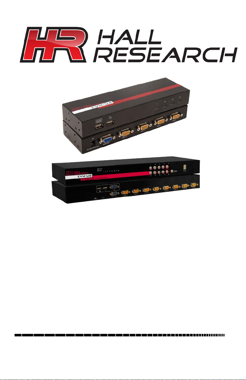
8 Port VGA
4 Port VGA
KVM-U4 & KVM-U8
KVM Switch
Users Guide
SUPPORT
INFORMATION
FREE technical support, Call 714-641-6607 or fax 714-641-6698
Mail order: Hall Research, 1163 Warner Ave. Tustin, CA 92780
Web site: www.hallresearch.com E-mail: info@hallresearch.com
KVM Switch
UMA 1180, Rev 1.1
Page 2

2
Page 3

Model KVM-U4 * KVM-U8
1
TRADEMARKS USED IN THIS MANUAL
Hall Research and its logo are trademarks of Hall Research.
Any other trademarks mentioned in this manual are acknowledged to be the
property of the trademark owners.
FEDERAL COMMUNICATIONS COMMISSION
RADIO FREQUENCY INTERFERENCE STATEMENT
This equipment generates, us es, and can r adiate radio frequency energy and
if not installed and used properly, that is, in strict accordance with the
manufacturer’s ins tructions, may cause interferenc e to radio communication.
It has been designed to comply with the limits for a Class A computing device
in accordance with the specifications in Subpart B of Part 15 of FCC rules,
which are intended to provide reasonable protection against such
interference when the equipm ent is operated in a commercial environment.
Operation of this equipment in a residential area is likely to cause
interference, in which case the us er at there own expense will be required to
take whatever measures may be necessary to correct the interference.
Changes or modifications not ex pres s ly approved by the party responsible for
compliance could void the user’s authority to operate the equipment.
This digital apparatus does not exceed the Class A limits for radio noise
emission from digital apparatus set out in the Radio Interference Regulation
of the Canadian Department of Communications.
CE
This equipment complies with the requirements of regulation:
EN 55 022: CLASS B.
Page 4

2
4 Port VGA KVM & 8 Port VGA KVM Switches
Contents
MODEL KVM-U4 ............................................................................................................................. 3
1.1 GENERAL................................................................................................................... 3
1.2 FEATURES ................................................................................................................. 3
1.3 PACKAGE CONTENTS ................................................................................................. 3
1.4 INSTALLATION ............................................................................................................ 3
1.5 HOTKEY..................................................................................................................... 3
2 KVM-U8 .................................................................................................................................. 4
2.1 GENERAL................................................................................................................... 4
2.2 FEATURES ................................................................................................................. 4
2.3 PACKAGE CONTENTS ................................................................................................. 4
2.4 FRONT PANEL ............................................................................................................ 5
2.5 REAR PANEL .............................................................................................................. 5
2.6 INSTALLATION ............................................................................................................ 5
2.7 DESKTOP OR RACK MOUNT ........................................................................................ 6
2.7.1 Desktop .......................................................................................................... 6
2.7.2 Rack Mounting .............................................................................................. 6
2.8 COMPUTER/SERVER INSTALLATION ............................................................................. 7
2.8.1 Daisy Chain Connections ............................................................................. 8
2.8.2 KVM Over IP ................................................................................................... 9
2.9 POWER ON SEQUENCE ............................................................................................ 10
2.10 HOTKEYS ................................................................................................................. 10
2.11 KEYBOARD MAPPING ................................................................................................ 12
2.12 OSD (ON SCREEN DISPLAY) .................................................................................... 13
2.13 LOGIN WINDOW ....................................................................................................... 13
2.14 STATUS SCREEN ...................................................................................................... 13
2.15 PORT NAME ............................................................................................................. 14
2.16 MAIN MENU ............................................................................................................. 15
2.16.1 Language ..................................................................................................... 15
2.16.2 Port Name Edit ............................................................................................ 15
2.16.3 Port Search .................................................................................................. 15
2.16.4 User Security ............................................................................................... 16
2.16.5 Access List .................................................................................................. 16
2.16.6 Hotkey .......................................................................................................... 16
2.16.7 Time Settings ............................................................................................... 16
2.16.8 OSD Mouse .................................................................................................. 17
3 TROUBLESHOOTING ......................................................................................................... 17
3.1 NO LED DISPLAY ON KVM SWITCH ........................................................................... 17
3.2 KEYBOARD OR MOUSE NOT WORKING ........................................................................ 17
3.3 NO VIDEO DISPLAYED ON THE MONITOR. .................................................................... 17
3.4 COMPUTER RESOLUTION DOES NOT MATCH THE MONITOR’S ....................................... 18
3.5 VIDEO IS FUZZY OR UNCLEAR .................................................................................... 18
4 TECHNICAL SPECIFICATIONS .......................................................................................... 19
5 FEATURES .......................................................................................................................... 20
Page 5

Model KVM-U4 * KVM-U8
3
Hotkey Command
Function
Scroll Lock + Scroll Lock + [Up Arrow]
Previous Channel
Scroll Lock + Scroll Lock + [Down Arrow]
Next Channel
Scroll Lock + Scroll Lock + [1,2,3,4]
Go to Port…
Scroll Lock + Scroll Lo ck + S
Toggle Auto Scan
Scroll Lock + Scroll Lo ck + B
Toggle Beep
MODEL KVM-U4
1.1 General
The KVM-U4 is a compact KVM switch for controlling up to 4 computers from
a single keyboard, mouse and monitor. It is designed for desktop or rack
mounting.
1.2 Features
• Hot key control
• Push button and Auto Scan switching
• Optional ear brackets for rack mounting
• Supports USB or PS2 (with adapter)
• Auto S can Mode for monitoring
• Audible alerts for confirmation
1.3 Package Contents
The KVM-U4 package contains the following contents:
• 1x KVM-U4 Switch
• 2x Rack Mount Brackets with mounting hardware
• 1x 9V DC Power Adapter
• 1x This Users Guide
1.4 Installation
1. Attach monitor to the monitor port on the back of the KVM-U4.
2. Connect mouse and keyboard directly to the USB ports on the front
of the KVM-U4.
3. Attach the HD15 end of a USB KVM cable (not included) to an
available Host port on the back of the KVM-U4.
4. Connect the other end of the USB KVM cable to the host computer
video and USB ports.
5. Power on the KVM-U4.
1.5 Hotkey
Page 6

4
4 Port VGA KVM & 8 Port VGA KVM Switches
2 KVM-U8
2.1 General
The KVM-U8 is a single rack unit 8-port VGA KVM switch to cont rol multiple
hosts from a single console. Hosts connect to the switch via a convenient
Video/USB combo cable. The switch cons ole natively accepts USB keyboard
and mouse but can use PS/2 with PS/2-USB adapters.
Up to 8 switches can be linked together to control up to 64 servers. The
switch may be accessed f rom any com puter on the LAN with optional plug-in
module (KVM-U8-IP).
2.2 Features
• On Screen Display (OSD) Menu
• Two levels of password security
• Hot key control
• Push button and Auto Scan switching
• Full keyboard and mouse emulation
• Provides ACL (Access Control List) secur ity with up to 8 independent
ACLs of controllable computer lists
• Hot pluggable – add or remove connected computers without
powering off the KVM switch or computers
• Plug-n-Play monitor support
• Keyboard state restored when switching between computers
• Daisy chainable function with both Bus (8-layer) and Tree (2-layer)
topologies
• Video/USB combo cables available in 6, 10 and 15 ft lengths.
• Optional KVM Over IP interface (KVM-U8-IP) to allow remote acc ess
to the switch from any PC on the LAN.
2.3 Package Contents
The KVM-U8 package contains the following contents:
• 1x KVM-U8 Switch
• 2x Rack Mount Brackets with mounting hardware
• 4x Foot pads
• 1x 12V DC Power Adapter
• 1x This Users Guide
Page 7
Model KVM-U4 * KVM-U8
5
Active Selection Indicator
Online Status Indicator
LED Bank Indicator
Reset Combination
Bank Selection
Port Selection
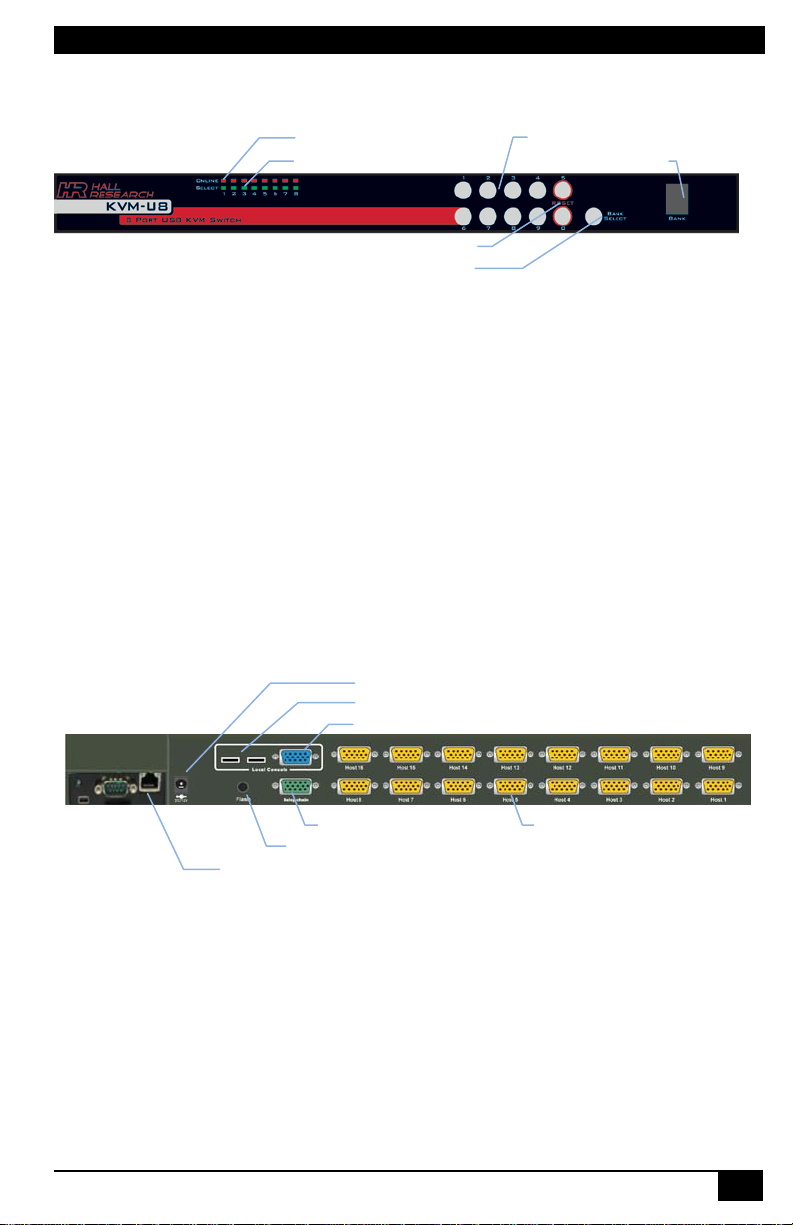
Console Keyboard/Mouse
Console Video/ Daisy Chain
Daisy Chain
Host Port Connector
Flash Upgrade
DC Power Jack
Optional KVM Over IP
2.4 Front Panel
Figure 1 - Front Panel
• Online Status Indicator: T he Red LED indicates when a computer
is connected and powered.
• Active Selection Indicator: The Green LED indicates which port is
selected. The LED will flash if no computer is connected to the port.
• Reset Combination: Press buttons 5 and 0 simultaneously to restart
the switch.
• LED Bank Indicator: This 7 segment LED indicates the selected
bank when multiple units are daisy-chained.
• Bank Selection: This button will cycle through daisy-chained banks.
• Port Selection: Press the 2 digit port num ber to immediately switch
to the port. For example, pr ess “0” then “ 6” to switch to port 6. Press
the single digit port number and wait 2 seconds to switch to the port.
2.5 Rear Panel
Figure 2 - Rear Panel
2.6 Installation
Before installation, please make sure all peripherals and computers are
turned off.
Page 8
6
4 Port VGA KVM & 8 Port VGA KVM Switches
2.7 Desktop or Rack Mount
The KVM-U8 can be m ounted on a desktop surface or in a single RU of a
standard 19” rack.
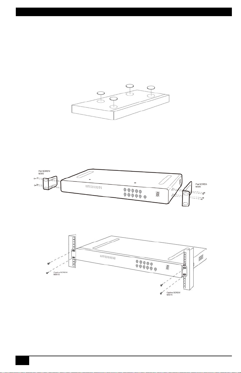
2.7.1 Desktop
1. Apply the self-adhesive footpads supplied in the package contents to
the four corners of the bottom panel.
Figure 3 - Desktop Installation
2.7.2 Rack Mounting
1. Connect the mounting brackets to the sides of the unit as shown
below.
Figure 4 - Mounting Bracket Instal lation
2. Slide the unit into the rack and secure it to the posts.
Figure 5 - Rack Mount Installatio n
Page 9

Model KVM-U4 * KVM-U8
7
2.8 Computer/Server Installation
The figure below depicts overall system installation with a single Daisy-Chain
slave unit.
Figure 6 – Computer/Server Installation Diagram
Page 10

8
4 Port VGA KVM & 8 Port VGA KVM Switches
Bank 1 (Master)
Bank 2 (Slave1)
Bank 3 (Slave2)
2.8.1 Daisy Chain Connections Up to 8 KVM-U8 switches can be daisy-chained together. Hall Research
Ultra-Thin cables ar e r ecommended f or us e in the daisy chain connection but
any VGA cable with 15 fully connected lines will work.
Connect the Daisy chain HD15 port of the previous switch to the Local
Console VGA port of the next switch in the series as shown below.
Figure 7 - Daisy Chain Connections
The console OSD menu will only show port information of the master KVM
switch. When the m aster switch starts up, it will query all daisy chained slave
units and automatically setup the Bank ID for each slave unit. The Master unit
Bank ID will display 1, Slave 1 will display 2, Slave 2 will display 3, and so on.
If the Bank I Ds are displayed incorrectly then reset the Master unit to update
the Bank ID information.
Page 11

Model KVM-U4 * KVM-U8
9
Other KVM switches c an also be daisy chained to the KVM-U8 through the
host ports. Note that the slave KVM switch m us t not use the sam e H otk ey as
the KVM-U8.
Figure 8 - Daisy Chain Through Host Port
2.8.2 KVM Over IP The KVM-U8-IP is a KVM over IP module that allows the KVM switch console
to be accessed through the browser of any PC on the network.
Figure 9 - KVM Over IP Console
Page 12

10
4 Port VGA KVM & 8 Port VGA KVM Switches
Lock
Caps
Lock
1 1 0
Installation
1. First power off the KVM-U8 switch.
2. Remove the add-on slot cover.
3. Slide in the KVM over IP module. Make sure it is fully inserted into
the slot.
4. Tighten the locking screw to secure the module in place.
5. Connect the RJ45 port to your network. Refer to the KVM-U8-IP User
Guide for more information about configuring and using this module.
2.9 Power On Sequence
Before turning anything on, verify all cables are properly connected in the
correct location.
The recommended power on sequence is as follows:
1. Monitors
2. KVM Switch
3. Computers
When the KVM-U8 is powered on the Port 1 Select LED will light up and you
should hear a beep sound. The Online Status LED's light up when the
connected host is powered on. If you encounter an error, check the cable
connections for that host and reboot. If the problem persists, please ref er to
the Troubleshooting chapter of this Users Manual.
2.10 Hotkeys
The KVM-U8 has multiple hotk ey commands f or quick control of the switch
functions.
The default hotkey is Caps Lock + Caps Lock. Press the key twice within 2
seconds to invoke the hotkey mode. You then have 2 seconds to enter a
command before the mode times out.
You can quickly switch between hosts by performing the hotkey sequence
Caps Lock, Caps Lock, [Bank ID], [2 digit host #]. For example, to switch
to Bank 1 Port 1 type the following sequence:
+ + + +
Caps
Page 13

Model KVM-U4 * KVM-U8
11
Space bar
[1,2,..,8] bank,
“01”.
PgUp
Previous bank
B
beep sound
Enable/disable Screen Saving and auto-logout function.
P
Set OSD back to factory defaults (except User Security
Lock
Lock
Command Function
Display the OSD Port Name screen
↑or↓
Move Up or Down through host ports
■ The first digit is the bank number starting with “1”.
[01, 02,..,32] port
■ The second & third digits are port number starting with
PgDn
L
Next bank
Enable/disable
Default is OFF (Disable).
Log out current user.
R
S
U
settings). Only SUPERVISOR can perform this action.
Enable/disable Auto-Scan. Only SUPERVISOR can perform
this action.
Enable/disable Security function. Only SUPERVISOR can
perform this action.
Table 1 - Hotkey Commands
There are two ways to invoke the OSD menu with hotkeys.
A. Keyboard – Hit Caps Lock + Caps Lock + Space
Caps
+ +
Caaps
Space Bar
B. Mouse – Press and hold the left mouse button and hit Esc key to
show the Status screen. Press and hold the right m ouse button and
hit the Esc key to bring up the OSD menu.
Page 14

12
4 Port VGA KVM & 8 Port VGA KVM Switches
Sun keyboard
Windows PS/2 keyboard
Stop
Caps Lock & L_Alt
Undo
Caps Lock & F5
Front
Caps Lock & F1
Copy
Caps Lock & F6
Open
Caps Lock & F2
Paste
Caps Lock & F7
Find
Caps Lock & F3
Cut
Caps Lock & F8
Volume up
Caps Lock & 3
Power
Caps Lock & F12
Help
Caps Lock & F11
Compose
Caps Lock & L_Shift (Application)
Sun OS
Windows key
MAC OS
Windows PS/2 keyboard
Shift
Shift
Ctrl
Ctrl
L Alt/Option
Alt
F13
PrtSc (Print Screen)
F14
ScrLk (Scroll Lock)
Return
Enter
Delete
Backspace
F15
Pause/Break
2.11 Keyboard Mapping
Again Caps Lock & F4
Props Caps Lock & L_Ctrl
Mute Caps Lock & 1
Volume down Caps Lock & 2
Table 2 - SUN Keyboard Mapping
Windows key
Table 3 - MAC Keyboard Mapping
Page 15

Model KVM-U4 * KVM-U8
13
Selected Bank ID.
Selected Port
Port Name
Hotkey
Screen Saving Status
2.12 OSD (On Screen Display)
The On Screen Display provides a graphical display and interface for
controlling the KVM-U8 switch. The OSD has 4 screens:
1. Login Window
2. Status Screen
3. Port Name
4. Main Menu
2.13 Login Window
If the security function is enabled (disabled by default), the Login window will
be displayed when the switch is powered up.
Figure 10 - Login Window
The default SUPERVISOR user name is “00000000” (8 zeros) and the
default password is “00000000” (8 zeros). Keep in m ind that the username
and password are case-sensitive even though the OSD only displays in upper
case.
2.14 Status Screen
The Status Screen displays setting information after login, OSD menu or
anytime the host is switched. Pressing any key or button will clear the status
screen.
Figure 11 - Status Screen
Screen Saving – If this option is enabled, the switch will turn off the display
and auto-logout after 10 minutes of console inactivity.
Page 16

14
4 Port VGA KVM & 8 Port VGA KVM Switches
Switch to the selected port
Show ports 25 ~ 32
Selected Bank
Selected Port
Hosts Online (Power on)
Firmware Version
2.15 Port Name
The Port Name screen lists the port names and status of a particular bank.
Figure 12 - Port Name Screen
Command Description
F1
F2
F3
Go to Main Menu
Log out
Previous Menu
Enter
↑ or ↓
PgUp
PgDn
Esc
1
2
3
Move Up or Down
Previous Bank
Next Bank
Exit
Show ports 01 ~ 08
Show ports 09 ~ 16
Show ports 17 ~ 24
4
Table 4- Port Name Screen Commands
Page 17

Model KVM-U4 * KVM-U8
15
2.16 Main Menu
The Main Menu has eight options: Language, Port Nam e Edit, Port Search,
User Security, Access List, Hotkey, Time Settings and OSD Mouse.
Figure 13 - Main Menu S cr een
2.16.1 Language The OSD supports English (default), French, German, Italian, Spanish, Simplified Chinese, Japanese, and Russian. Note that editing the settings can only be done with English alphanumeric.
2.16.2 Port Name Edit You can enter custom names for each host port on any connected bank.
Figure 14 - Port Name Edit Window
Use keyboard arrows or mouse to navigate the list. Use PgUp and PgDn to
toggle through available Banks. Select the port and press Enter once to edit
the name and press Enter again to exit edit mode. Press Esc at any time to
exit.
2.16.3 Port Search Port Search allows you to search all port names for a particular string of characters.
Page 18

16
4 Port VGA KVM & 8 Port VGA KVM Switches
Port name
Users
2.16.4 User Security
The KVM-U8 supports two user levels: SUPERVISOR and USER. There can
only be one SUPERVISOR and up to eight USERs.
Figure 15 - User Security Screen
The first name, S is the SUPERUSER account. The default usernam e and
password is “00000000”.
2.16.5 Access List
The Access List allows the SUPERVISOR account to assign access
privileges to individual USER accounts.
Figure 16 - Access List Window
Port #
Use arrow keys to navigate the list. Lef t c lick mouse or pres s ‘Enter ’ to toggle
each cell between O=grant and X=deny user access to the port.
2.16.6 Hotkey
Hotkey menu allows you to change the hotkey. Hotkey must be pressed twice
within two seconds to activate and will time out after two seconds if no key is
pressed.
2.16.7 Time Settings
When Auto-Sc an function is enabled the switch will auto-scan through online
host ports based on the interval of the scan time setting. The interval range is
5 – 99 seconds and the default interval time is 10 seconds.
Page 19

Model KVM-U4 * KVM-U8
17
2.16.8 OSD Mouse
This setting allows you to change the speed of the c ursor in the OSD. The
three available settings are SLOW, MIDDLE, and FAST.
3 Troubleshooting
3.1 No LED display on KVM Switch
• Make sure the KVM Switch has power. If the LED’s st ill won’t light,
perform a soft reset to KVM switch.
• Power cycle KVM switch.
3.2 Keyboard or mouse not working
• Make sure your keyboard and mouse work fine if directly plugged
into the computer.
o PS/2 computer --- keyboard and mouse are not hot
pluggable, please make sur e PS/2 cables are well connected
then reboot the computer.
o USB computer ---- unplug and plug in the USB connector,
wait a few seconds for USB bus emulations and start up
process to complete.
• Do not press any keys on the keyboard while the selected computer
is booting up. Otherwise it might cause a keyboard error or k eyboard
to not be detected on the host side.
• Try a different keyboard. Use only 101/102/104-key keyboard.
• Power cycle the unit.
• Avoid moving the mouse or pressing the mouse buttons when
switching ports.
3.3 No video displayed on the monitor.
• Verify all connectors are connected properly.
• Connect your monitor directly to the server to verify that your monitor
is functioning properly.
• Bring up the OSD and confirm the port is selected and connected to
a host.
• Make sure the computer VGA output resolution is s upported by the
monitor
Page 20

18
4 Port VGA KVM & 8 Port VGA KVM Switches
3.4 Computer resolution does not match the monitor’s
• Verify if the monitor works fine if directly connected to the computer.
• Turn off the computer, wait few seconds then restart. During startup,
the computer will try to obtain EDID information about the monitor.
Make sure the monitor and KVM switch are ON and running before
restarting the computer.
• The switch will dynamically detect and copy the EDID information
from the monitor attached to the LOCAL console port. That
information will feed to the host computer during startup.
• The recommended Power ON sequence is as follows: monitor , KVM
Switch, finally the computers.
3.5 Video is fuzzy or unclear
• Verify if the VGA connector is firmly connected.
• If using the remote console extender, make s ure to use high quality
cables free from defects.
Page 21

Model KVM-U4 * KVM-U8
19
KVM Type
4 Technical Specifications
Feature KVM-U4 KVM-U8
Combo VGA Combo VGA
Host Port Connector VGA VGA
Host Ports 4 8
Console Type USB or PS/2 USB or PS/2
Max. Distance
(KVM switch -- Host)
Video Resolution
(Local Console)
Video Resolution
(Remote Console)
Console Ports
IP-Based Remote
Module (KVM-U8-IP)
Daisy Chain
Computers Selection
Hotkey Scroll Lock + Scroll Lock Caps Lock + Caps Lock
7-seg LED NA 1 set for Bank display
Table 5- Technical Specifications
16 feet (5m) 16 feet (5m)
1920 x 1440 1920 x 1440
NA
Local console
Local console
NA
NA
• Hot Key
• Push Button
Optional Modules: IP-Based
Remote Console
• RJ-45 8P8C for 10/100M
• DB-9 male for Configuration
• Mini USB 2.0 receptacle
• Support Daisy Chaining with
• Connector DB15 (Female
• Hot Key
• Push Button
• On Screen Display (OSD)
1600 x 1200 for IP-Based
remote console
Ethernet
console, Modem, Null
modem, and serial power
control
both Bus (8-layer) and Tree
(2-layer) topologies
Type)
Menu
Page 22

20
4 Port VGA KVM & 8 Port VGA KVM Switches
Mouse Emulation
5 Features
Feature KVM-U4 KVM-U8
Provide ACL (Access Control
Security
Multilingual OSD (On Screen
Display) control
Auto-Scan Intervals 8 seconds 5 ~ 99 Sec.
Keyboard Emulation PS/2 or USB
Max. Connected Computers 4 Up to 8192
Housing Metal Metal
Power
Operation Temperature
Storage Temperature
Humidity 0~80%, Non-Condensing 0~80%, Non-Condensing
Mechanical
Dimension (mm) 158 x 74 x 25 444.5 x 160 x 44.3
DC Power adapter : 9V,
NA
NA
PS/2 or USB
500mA
0 ~ 50℃ 0 ~ 50℃
-20 ~ 60℃ -20 ~ 60℃
Desktop or 19”
Rackmount, 1U
List) security function, store
up to 8 independent ACL’s of
controllable computer lists
8 languages (English, France,
Germen, Spanish, Italian,
Russian, Japanese, Simplified
Chinese)
DC Power adapter : 12V, 1A
19” Rackmount, 1U
Page 23

Page 24

Order toll-free in the U.S. 800-959-6439
CUSTOMER
© Copyright 2011. Hall Research, Inc.
All rights reserved.
SUPPORT
INFORMATION
FREE technical support, Call 714-641-6607 or fax 714-641-6698
Mail order: Hall Research, 1163 Warner Ave. Tustin, CA 92780
Web site: www.hallresearch.com E-mail: info@hallresearch.com
 Loading...