

Page 1
© Copyright 2012. Hall Research, Inc. All rights reserved.
1163 Warner Ave Tustin, CA 92780, Ph: (714)641-6607, Fax (714)641-6698
User’s Manual
UMA1183 Rev A
Model HR-733
Fiber optic Video Extender
Extend HDMI™/DVI or VGA/YPbPr
together with Full-Duplex RS-232 over a
Single Fiber Optic Cable
Page 2

Page 3

1
HDMI, VGA/YPbPr, and Serial over Single Fiber
TRADEMARKS USED IN THIS MANUAL
Hall Research and its logo are trademarks of Hall Research.
Any other trademarks mentioned in this manual are acknowledged as the property of the
trademark owners.
FEDERAL COMMUNICATIONS COMMISSION
RADIO FREQUENCY INTERFERENCE STATEMENT
This equipment generates, uses, and can radiate radio frequency energy and if not installed
and used properly, that is, in strict accordance with the manufacturer’s instructions, may
cause interference to radio communication. It has been designed to comply with the limits
for a Class A computing device in accordance with the specifications in Subpart B of Part
15 of FCC rules, which are intended to provide reasonable protection against such
interference when the equipment is operated in a commercial environment. Operation of
this equipment in a residential area is likely to cause interference, in which case the user at
their own expense will be required to take whatever measures may be necessary to correct
the interference.
Changes or modifications not expressly approved by the party responsible for compliance
could void the user’s authority to operate the equipment.
HDMI™, the HDMI™ Logo, and High-Definition Multimedia Interface are
trademarks or registered trademarks of HDMI™ Licensing LLC
Page 4

2
Model HR-733
Table of Contents
1.0 General ............................................................................................... 3
2.0 Features .............................................................................................. 3
3.0 Precautions ......................................................................................... 4
4.0 Theory of Operation .......................................................................... 5
5.0 Installation .......................................................................................... 6
5.1 Required Cables ............................................................................... 6
5.2 Inputs & Outputs .............................................................................. 6
5.3 Fiber Optic Cable Requirements ...................................................... 6
5.4 Status of LED Indicators .................................................................. 7
6.0 Operation ............................................................................................ 8
6.1 Front Panel Buttons ......................................................................... 8
6.2 HR-733-S LCD Menu System ......................................................... 9
6.3 LCD Menu Detailed Descriptions .................................................. 13
6.4 More on RS-232 ............................................................................ 15
6.5 Using the HR-733-S in Command Mode ....................................... 16
6.6 RS-232 Control Commands ........................................................... 17
7.0 Troubleshooting ............................................................................... 18
8.0 Specifications .................................................................................... 18
Page 5
HDMI, VGA/YPbPr, and Serial over Single Fiber
3
1.0 General
Thank you for purchasing the Hall Research HR-733 fiber-optic video
Extender. The HR733 is a 3 input multi-format HD video extender with
bi-directional RS-232 extension and control.
The device can select among 2 HDMI (or DVI) inputs and 1 VGA (or
YPbPr) input and extend the selected source as an uncompressed digital
signal over a single multi-mode fiber to a remote receiver. The device
supports embedded audio on the HDMI inputs, and provides separate R/L
analog or SPDIF (TOSLINK) digital audio inputs for the VGA input.
The HR-733 can also extend a bi-directional data channel (CEC, or RS232 Serial) over a single multi-mode (OM2 or OM3) fiber optic cable
spanning distances of up to 1000m (3280ft).
The compact remote unit provides an HDMI output (with embedded
audio) for simple AV connectivity to any display.
The RS-232 port can be used as an extension, or at the same time it can be
used to control the Sender (e.g. to select inputs). A user-friendly front
panel with high-contrast alphanumeric LCD enables the user to easily set
up and control the system.
Advanced features include: automatic scaling of the analog video input to
match the native resolution of the remote display, diagnostic messages on
the front panel LCD (e.g. RS-232 strings sent or received), audio delay of
the analog input to correct lip-sync, support for CEC data channel of
HDMI (choice of RS-232 or CEC extension), and 3D deep-color HDMI
1.4 support (without ARC or Ethernet extension).
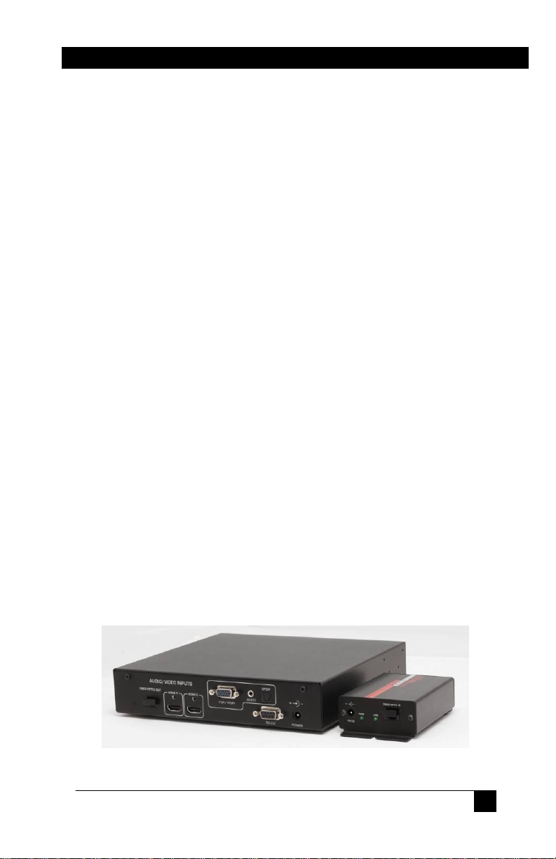
The Sender unit is designed as a ½ wide 1RU with threaded holes so that
two can be mounted side by side on a tray (Model RMS-1U-1A), or a
single unit can be rack mounted using supplied brackets (pair of F10375).
Figure 1 – Model HR-733 Sender and Receiver
2.0 Features
Page 6
4
Model HR-733
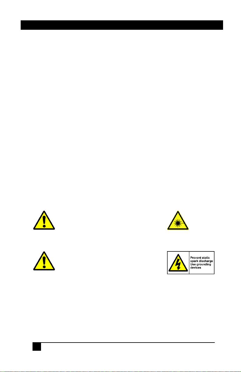
This device is a Class 3R Laser device
(per IEC 60825-1:2007) and can cause
damage to eye sight if used improperly.
Refer to ANSI Z136 for proper handling
and usage of Class 3R devices.
This device is sensitive to Electrostatic
Discharge (ESD). Prior to touching the
unit (especially the connectors), touch a
grounded object, and make sure the
devices that will be plugged in to the
HR-733 are properly grounded.
3 video inputs (2 HDMI and 1 VGA/YPbPr with Audio)
Transmits uncompressed HDMI video along with RS-232 to 1000m
Supports Deep-color (HDMI 1.3 or 1.4) and 3D
Compatible with DVI video (with DVI to HDMI input cable)
Converts PC VGA or component video and audio to HDMI at any
resolution
Automatically detects VGA/YPbPr input and timing parameters
Front panel LCD readout for easy setup and control
Status indication of fiber-optic link, remote LCD (hot-plug), and
Source video
Bi-directional RS-232 data transmission between the sender and the
receiver
RS-232 control of the input source selection and setup
1RU high Sender includes rack-mount brackets, and Receiver has
surface mounting provisions
Safety interlock does not turn on high-power fiber LED drivers
unless fiber-optic cable is plugged in at both ends
Front panel button functions can be locked through serial port
Locking HDMI connectors
Green design, turns off parts of circuit when they are not in use
Compact, Rugged, Reliable, and Economical
Made in USA
3.0 Precautions
Page 7
HDMI, VGA/YPbPr, and Serial over Single Fiber
5
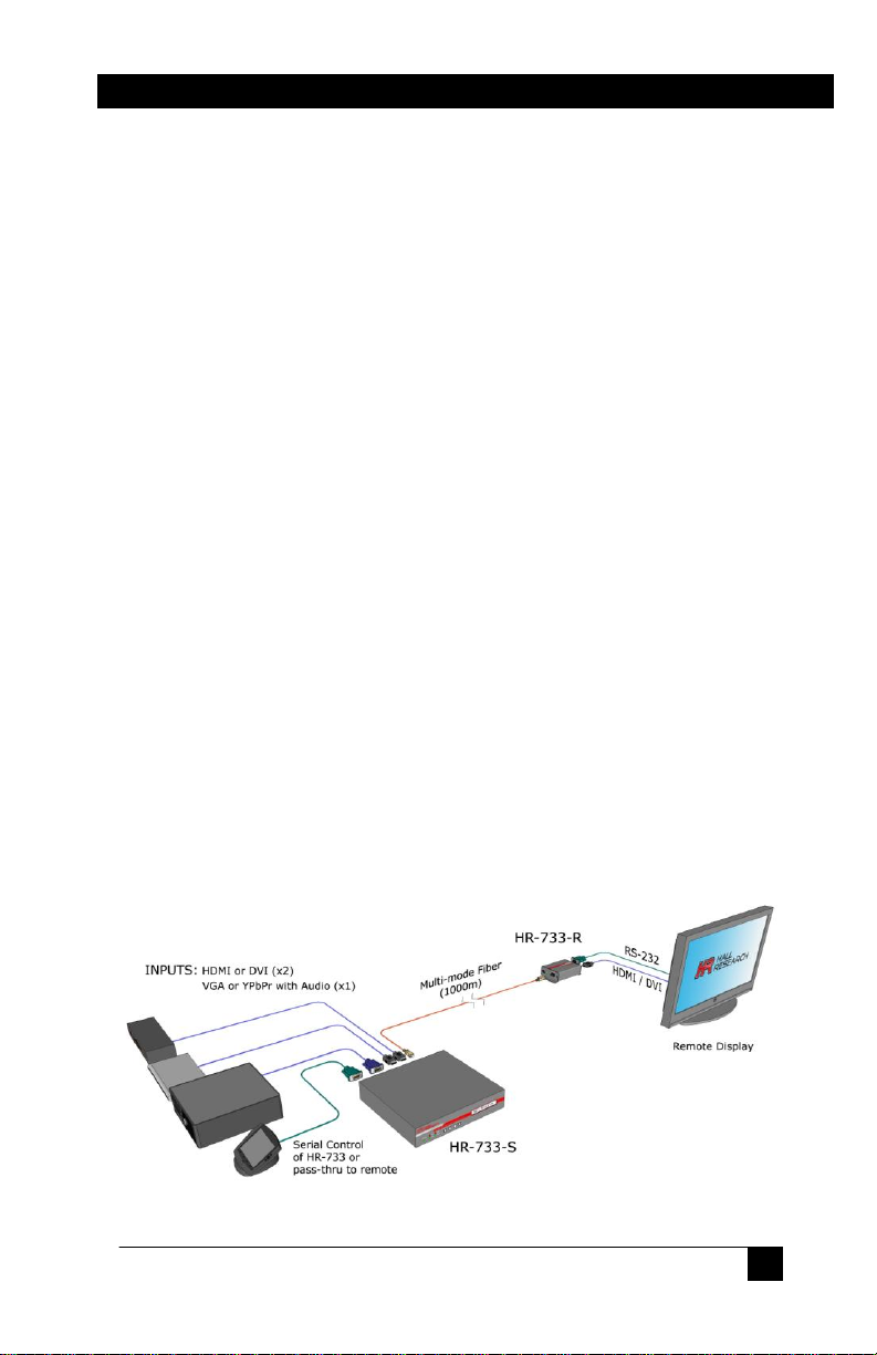
4.0 Theory of Operation
The Sender provides both digital (HDMI/DVI), and analog (VGA/YPbPr
+ audio) inputs. However, in the fiber video is transmitted as digital
regardless of the selected input, and always comes out as HDMI on the
receiver with audio embedded in the video on the same connector. When
the analog input is selected, its video and audio are digitized and scaled to
match the native resolution of the remotely connected LCD.
The video data is transmitted on only one multi-mode fiber. The reason
multi-mode cable is needed is because the TMDS data are transmitted
over a range of optical wavelengths to reduce bandwidth requirement at
any particular wavelength. The TMDS signals use LED lasers to drive the
cable. However, for safety reasons, these lasers are not turned on if no
fiber optic cable is plugged in at both the Sender and Receiver.
Additional (non-video) DVI or HDMI signals are also seamlessly
connected between the source and the sink device. These include:
DDC Channel (SDAT and SCLK) for EDID and HDCP
Hot Plug Detect (to detect remote monitor connection)
Source Active +5vDDC (to indicate to sink there is a source)
In addition, the fiber-optic link provides a general purpose bi-directional
data lane that can be assigned by the user to be used as RS-232 passthrough between sender and receiver, or to extend the CEC standard of the
HDMI. Currently CEC is seldom used in pro-AV installations, and its
implementation varies from one TV manufacturer to another, so as default
the HR-733 uses the data lane for RS-232 communication and control.
However, the CEC can be selected by the user, in which case the RS-232
port on the remote unit will not serve any function (the RS-232 port on the
Sender can still be used for source selection).
Figure 2 - Connection Block Diagram
Page 8

6
Model HR-733
Figure 3
SC Fiber Connector
5.0 Installation
5.1 Required Cables
1 or 2 HDMI cables to connect up to 2 HDMI sources to the HR-
733-S
HDMI cable to connect the HR-733-R to the HDMI display
HD-15 male-to-male VGA cable to connect a PC analog video or
an HD-15 to 3-RCA for component YPbPr DVD video
connection to the HR-733-S
3.5mm stereo audio cable or optical (TOSLINK) audio cable to
connect associated audio of VGA/YPbPr source to the sender
RS-232 DB9 male-to-female (pin to pin) cable to connect the
HR-733-S’s serial port to a PC
Multi-mode (MM) fiber-optic cable to connect the HR-733-S and
HR-733-R
5.2 Inputs & Outputs
The HR-733-S has 2 HDMI inputs, 1 VGA/YPbPr input with audio, and a
bi-directional RS232 port. The audio source of the VGA/YPbPr input can
be either 3.5mm L/R stereo or optical.
The HR-733-R has l HDMI output and 1 bi-directional RS232 port.
5.3 Fiber Optic Cable Requirements
Each end of the HR-733 uses a single SC connector and requires a multimode fiber-optic cable. Unlike some other fiber-optic equipment that may
work with either single-mode or multi-mode cables,
the HR-733 is not compatible with single-mode
cables. Multi-mode cables are generally available in
OM1, OM2, or OM3 constructions. The OM3
cables are best suited for max transmission lengths
and are recommended for this product.
Page 9

HDMI, VGA/YPbPr, and Serial over Single Fiber
7
Data Rate
OM1
(62.5/125 µm )
OM2
(50/125 µm )
OM3
(50/125 µm )
1.65 Gb/s
(HDMI 1.2a)
250 m (820 ft)
500 m (1640 ft)
1000 m (3280 ft)
3.4 Gb/s
(HDMI 1.3, 1.4)
150 m (500 ft)
250 m (820 ft)
500 m (1640 ft)
The above table shows the maximum possible cable lengths based on data
rates for 1080p resolution with normal 8-bit color per HDMI 1.2a, as well
as deep color per HDMI 1.3 or 1.4, versus different cable constructions.
The max specified distances disregard inter-pair skew. A maximum interpair skew of 0.6 * Tpixel (as required by HDMI specifications) would
limit the max distance to 600 meters regardless of cable construction at
1080p resolution. However, most HDMI equipment can tolerate skews
larger than that.
5.4 Status of LED Indicators
PWR: Solid GREEN –Unit is in operation.
OFF – Unit is off or not operational.
LINK: Solid RED – Optical link has been established between
the sender and the receiver.
OFF – Optical link has not been established between the
sender and the receiver.
SOURCE: Solid GREEN – Source detected on the sender.
OFF – No source detected on the sender.
HPD: Solid RED – Hot plug detect is active (there is a monitor
OFF – No hot plug detect is present (there is no LCD
VIDEO: Solid GREEN – There is TMDS clock (digital video is
OFF – Source is not outputting digital video.
(Note that for Source #3 VGA input, due to the built-in
Converter, the source LED will be lit regardless of
connection of VGA input)
plugged to the remote unit and/or it is turned on).
connected to the remote, or it is off).
coming from Source)
(Note that for Source #3 VGA input, due to the built-in
Converter, the source LED will be lit regardless of
connection of VGA input)
Page 10

8
Model HR-733
6.0 Operation
The HR-733-S has 4 buttons and an LCD display on the front panel which
allows users to easily navigate through the menu and change the settings.
6.1 Front Panel Buttons
The 4 buttons are used to do the following tasks:
The UP and DOWN buttons indicated by ▲and ▼ can be used
to navigate through the menu and to adjust the setting.
The ENTER button when pressed will go into the selected
menu. It is also used to save the setting when you exit.
The MENU is used to exit to the previous menu without saving
the setting.
NOTE
Symbol on the LCD is used to indicate the currently
selected option
Figure 4 – HR-733-S Front and Rear Views
Figure 5 – HR-733-R Front and Rear Views
Page 11

HDMI, VGA/YPbPr, and Serial over Single Fiber
9
every 3 seconds
Screen toggles
HR-733 Extender
View Menu, Use
(7.1)
(6.1)
(5.1)
(3.1)
(1.1)
(7)
(6)
(5)
(4)
(3)
(2)
(1)
SOURCE SELECT
VGA/YPbPr ADJUST
DATA CHANNEL
RS232 SETTINGS
MENU CONTRAST
FACTORY DEFAULT
DIAGNOSTICS
HDMI/DVI 2
RS232
-…....... …….......+
Use to confirm
Off
6.2 HR-733-S LCD Menu System
Figure 6 - Idle Menu
HDMI/DVI 1
HDMI/DVI 2
VGA/YPbPr
RS232
CEC
RS232 TxD
RS232 RxD
Off
Figure 7 - Top Level Menu
Page 12

10
Model HR-733
(2.10a)
(2.7a)
(2.6a)
(2.5a)
(2.4a)
(2.11)
(2.10)
(2.9)
(2.8)
(2.7)
(2.6)
(2.5)
(2.4)
(2.3)
(2.2)
(2.1)
(2)
VGA/YPbPr ADJUST
INPUT TYPE
OUTPUT
AUDIO
SIZE
PICTURE MODE
CONTRAST
BRIGHTNESS
FINE TUNE
COLOR
SHARPNESS
Auto
Full
Movie
Contrast: 43
Brightness: 54
Sharpness: 18
Auto
VGA
YPbPr
Full
Overscan
Underscan
Letterbox
Panscan
Standard
Movie
Vivid
User
Figure 8 - VGA/YPbPr Menu
Page 13

HDMI, VGA/YPbPr, and Serial over Single Fiber
11
(2.2a)
(2.2)
OUTPUT
1600x1200
(2.3c)
(2.3ca)
(2.3ba)
(2.3aa)
(2.3b)
(2.3a)
(2.3)
AUDIO
SOURCE
L/R
DELAY
SOUND
Off
On
Native
640x480
800x600
1024x768
1024x800
1440x900
1280x1024
1400x1050
1600x1200
1680x1050
1920x1200
480i
480p
576i
576p
720p at 50
720p at 60
1080i at 50
1080i at 60
1080p at 50
1080p at 60
Figure 9 - VGA/YPbPr Output Resolution Menu
L/R Off On
Optical 40ms Mute
110ms
150ms
Figure 10 - VGA/YPbPr Audio Menu
Page 14

12
Model HR-733
(2.8da)
(2.8ca)
(2.8ba)
(2.8aa)
(2.8d)
(2.8c)
(2.8b)
(2.8a)
(2.8)
FINE TUNE
PHASE
CLOCK
H-POSITION
V-POSITION
Phase: 61
Clock: 49
H-Position: 50
V-Position: 98
(2.9ca)
(2.9ba)
(2.9aa)
(2.9c)
(2.9b)
(2.9a)
(2.9)
COLOR
RED
Red: 48
GREEN
BLUE
Green: 48
Blue: 52
Figure 11 - VGA/YPbPr Fine Tune Menu
Figure 12 - VGA/YPbPr Color Menu
Page 15

HDMI, VGA/YPbPr, and Serial over Single Fiber
13
(4.3a)
(4.3)
(4)
(4.2a)
(4.1a)
(4.2)
(4.1)
RS232 SETTINGS
RS232 BAUD
19200
RS232 PARITY
RS232 FLOW CTRL
None
None
1200 None None
2400 Odd
4800 Even
9600
19200
38400
57600
115200
Figure 13 – RS-232 Settings Menu
NOTE
If there is no user activity for 1 minute, the idle menu will be
shown and LCD backlight will be off. Pressing any button will
take the user back to the previous menu.
6.3 LCD Menu Detailed Descriptions
The following paragraphs explain in further detail the function of each menu
choice. The numbers in parenthesis () refer to the corresponding menu level in
figures 6 through 13 in the previous section.
(1) SOURCE SELECT – This menu allows the user to select one of the three
input sources: HDMI/DVI #1, HDMI/DVI #2, or VGA/YPbPr.
(2) VGA/YPbPr ADJUST – This menu gives the user the ability to fine-tune the
way input #3 (VGA or component YPbPr) is converted into an HDMI or DVI
signal. The unit can embed an associated audio in to the video. The audio can be
either L/R analog on 3.5mm mini stereo or digital SPDIF on TOSLINK connector.
(2.1) INPUT TYPE – This is used to specify the type of analog video
that is going to be fed to the unit. Select either a PC analog VGA or
Page 16

14
Model HR-733
component YPbPr input as the source. It can also be set to Auto. In auto
mode the unit will try to determine if the input is VGA or YPbPr. This is
the default setting.
(2.2) OUTPUT – This allows the user to select the output resolution
from a large selection of possible settings. The output setting is
independent of the input timing and resolution. The output resolution
setting can automatically match the native resolution of the display that
the receiver HR-733-R is connected to, or may be specified by the user.
(2.3) AUDIO – The audio source of VGA/YPbPr can be either a line
level analog as L/R or optical digital as Optical. The audio source can
be set to 40ms, 110ms, or 150ms delay for audio/video
synchronization/timing alignment. If needed, the audio source can be
set to Mute.
(2.4) SIZE – The video image of VGA/YPbPr source can be set to
various sizes such as Full, Overscan, Underscan, Letterbox, and
Panscan to enable users to adjust displayable area of some displays if
needed.
(2.5) PICTURE MODE – This is used to adjust color and picture
settings of the VGA/YPbPr input source to one of the options such as
Standard, Movie, Vivid, and User. You can change the picture mode
to get the best picture from different sources in different environments.
(2.6) CONTRAST – This is used to set difference between light and
dark areas.
(2.7) BRIGHTNESS – This is used to brighten or darken the picture of
the VGA/YPbPr input source.
(2.8) FINE TUNE – This menu can be used to fine tune to picture of
the input source such as PHASE, CLOCK, Horizontal, and Vertical
Position.
(2.9) COLOR – This menu enables the user to use advanced settings to
adjust the color of the picture including RED, GREEN, and BLUE.
(2.10) SHARPNESS – This is used to sharpen or soften the picture.
(3) DATA CHANNEL – This menu gives the user an ability to choose the data
path between the sender and the receiver as either RS232 channel or CEC
(Consumer Electronic Control) channel. When RS232 channel is selected, serial
data can be transmitted in both directions between the sender and the receiver. If
the CEC channel is selected, the CEC is used for basic automatic control between
HDMI input source from the sender and HDMI output source from the receiver.
The RS-232 connection to the sender always operates at fixed 9600 baud, whereas
the receiver baud rate and parity can be set to match the device (projector or other
display) that it is connected to.
Page 17

HDMI, VGA/YPbPr, and Serial over Single Fiber
15
DB9-Female on HR-733-S
DB9-Male on HR-733-R
Pin
Function
Pin
Function
2
TX (output)
2 RX (input)
3
RX (input)
3 TX (output)
5
Ground
5 Ground
The reason the sender baud rate is fixed, is because the RS-232 can also be used to
specifically control the sender functions (such as selecting input source channel,
please see sections 5.4 through 5.6).
(4) RS232 SETTINGS – This menu allows users to set a specific baud rate and
parity for the receiver to control a projector or other serially controlled device.
Remember the baud rate of the Sender is fixed at 9600
(5) MENU CONTRAST – This is used to adjust the front panel LCD contrast.
(6) FACTORY DEFAULT – This is used to set all settings of both the sender
and the receiver back to factory defaults. Once you get in this menu, the ENTER
button can be pressed to set the HR-733 to factory defaults.
(7) DIAGNOSTICS – The diagnostic feature can be turned on to display the
serial data transmitted or received at the RS-232 port of the sender. This feature is
turned off by default.
6.4 More on RS-232
The RS-232 pin-out on the Sender and Receiver are shown below.
The HR-733 provides users the ability to control some of the features of
the Sender (such as input source selection), and if the data channel link to
the remote Receiver is set for RS-232 rather than CEC (in menu 3.1), then
the RS-232 port can also transmit or receive any serial data between the
sender and the receiver.
Most PCs and notebooks do not have a
serial port. So to program the Switch you
may need a USB to RS-232 Serial
converter. These are available from Hall
Research (Model USB-RS232-1).
In a typical application the remote receiver is connected to a display or a
video projector. In this case the RS-232 pass-through feature is used to
control the remote display (such as turning it on or off). Depending on the
specification of the remote display, the baud rate of the remote unit can
vary. Through the OSD menu of the HR-733 or the serial port in command
Note on RS-232 port availability on your PC
Page 18

16
Model HR-733
mode, you can specify the remote unit’s serial parameters (baud-rate and
parity). However, please note that the Sender’s baud rate is fixed at 9600.
In this way the PC or other serial device (such as touch-screen control
system) uses 9600 baud rate to communicate with HR-733-S. The system
takes care of baud-rate changes that are needed at the remote end, and
using FIFO buffers ensures no data is lost.
The RS-232 port on the sender can also control the sender in command
mode. This is done by appending a special set of characters to the serial
data that is sent to the HR-733-S.
6.5 Using the HR-733-S in Command Mode
If the data received at the serial port contains ==> (equal, equal, greater
than), then the Sender will interpret it as start of a command sequence. In
this mode you can specify one of the commands described in the following
section. The unit will stay in command mode until it gets a Carriage
Return <cr>. Once a command is executed, the unit will go back to Serial
pass-through mode (if data channel is configured that way). The ==>
and command sequence are not transmitted to the HR-733-R remote unit.
Most commands (such as input channel selection), can be issued to the
HR-733-S regardless of how its data channel is configured (CEC or RS232 pass through). There are a few commands that cannot be executed in
CEC mode as noted below.
Page 19

HDMI, VGA/YPbPr, and Serial over Single Fiber
17
6.6 RS-232 Control Commands
All commands are prefixed with ==>
All commands and responses are followed with a carriage return <CR>
Wrong commands will get a response of ERR1
Command: SCn stands for input Source Channel where n=(0-3,?). (0 =
Response: SCn
Command: PLn stands for front Panel Lock where n=(0-1,?). (0 = unlocked, 1
Response: PLn
Command: SBn stands for Set Baud of remote unit where n=(0-7,?). (0 =
Response: SBn
Condition: This command can only be executed when the fiber-optic data
Command: SPn stands for Set Parity of remote unit where n=(0-2,?). (0 =
Response: SPn
Condition: This command can only be executed when the fiber-optic data
Command: DCn stands for Data Channel configuration where n=(0,1,?). (0 =
Response: SPn
Command: FD stands for Factory Default –factory default settings will be
Response: FD
Command: FW? stands for Firmware Version query
Response: FW Version #
Blank, 1= HDMI#1, 2 = HDMI#2, 3 =VGA/YPbPr, ? = query input)
= locked, ? = query lock status)
1200, 1 = 2400, 2 = 4800, 3 = 9600, 4 = 19200, 5 = 38400, 6 =
57600, 7 = 115200, ? = query baud rate)
channel is configured for RS-232. If this command is issued in CEC
mode the front panel will show a notice to change to RS-232 mode,
and the serial port response will be ERR2
none, 1 = odd, 2 = even, ? = query Parity)
channel is configured for RS-232. If this command is issued in CEC
mode the front panel will show a notice to change to RS-232 mode,
and the serial port response will be ERR2
RS-232, 1 = CEC, ? = query Parity)
restored. This may take as long as 7 seconds
Page 20

18
Model HR-733
7.0 Troubleshooting
Make sure that all of the connections to the units are solid, and check the
state of the LED’s on the front of the unit. Do not open or try to repair the
unit yourself. There is no customer repairable item in the unit and you will
void your warranty.
Contact HR Support at 714-641-6607 or via email or web. If you need to
ship your unit for repair, make sure to get a Return Material Authorization
(RMA) number first.
8.0 Specifications
Video Inputs 2x HDMI or DVI, 1x VGA or YPbPr
Supported
Resolutions PC from VGA to WUXGA, HDTV from 480i to 1080p
Audio Inputs 3.5mm stereo, TOSLINK optical for VGA/YPbPr
Optical
Wavelength 780 nm to 980 nm
Optical
Cable Simplex (only 1 fiber) Multi-Mode. OM2 or OM3
Temperature Operating: 32 to 122°F (0 to 50°C);
Storage: –40 to +185°F (–40 to +85°C)
Enclosure HR-733-S: Steel, HR-733-R: Steel & Aluminum
MTBF 90,000 hours (calculated estimate)
Power 5V DC, 2.6A
Size Sender: 1.66 H x 8.2 W x 7.826 D (4.2x20.8x19.8 cm)
Receiver: 1.25 H x 2.75” W x 4.28” D (3.2x7.0x10.9 cm)
Weight Sender: 2.7 pounds (1.22 kg)
Receiver: 0.4 pounds (0.18 kg)
Page 21

HDMI, VGA/YPbPr, and Serial over Single Fiber
19
Page 22

Page 23

Page 24

© Copyright 2012. Hall Research, Inc.
All rights reserved.
1163 Warner Ave., Tustin, CA 92780
Ph: (714)641-6607, Fax: (714)641-6698
 Loading...