

Page 1
© Copyright 2014. Hall Research, Inc. All rights reserved.
UMA1208 Rev 2
User’s Manual
Model HR-731-S
Fiber optic Video Sender
Extend HDMI™or DVI
and RS-232 over a Single Fiber Optic Cable
1163 Warner Ave Tustin, CA 92780, Ph: (714)641-6607, Fax (714)641-6698
Page 2

Page 3

1
HDMI and Serial over Single Fiber
TRADEMARKS USED IN THIS MANUAL
Hall Research and its logo are trademarks of Hall Research.
Any other trademarks mentioned in this manual are acknowledged as the property of the trademark
owners.
FCC RADIO FREQUENCY INTERFERENCE STATEMENT
This equipment generates, uses, and can radiate radio frequency energy and if not installed and used
properly, that is, in strict accordance with the manufacturer’s instructions, may cause interference to
radio communication. It has been designed to comply with the limits for a Class A computing
device in accordance with the specifications in Subpart B of Part 15 of FCC rules, which are
intended to provide reasonable protection against such interference when the equipment is operated
in a commercial environment. Operation of this equipment in a residential area is likely to cause
interference, in which case the user at their own expense will be required to take whatever measures
may be necessary to correct the interference. Changes or modifications not expressly approved by
the party responsible for compliance could void the user’s authority to operate the equipment.
Table of Contents
1.0 General ................................................................................................ 2
2.0 Features .............................................................................................. 3
3.0 Precautions ......................................................................................... 3
4.0 Theory of Operation .......................................................................... 4
5.0 Installation .......................................................................................... 4
5.1 Required Cables ............................................................................... 5
5.2 Fiber Optic Cable Requirements ...................................................... 5
5.3 Status of LED Indicators .................................................................. 5
6.0 Operation ............................................................................................ 6
6.1 More on RS-232 ............................................................................... 7
6.2 Using the HR-731-S in Command Mode ......................................... 7
6.3 RS-232 Control Commands ............................................................. 8
7.0 Troubleshooting ................................................................................. 9
8.0 Specifications ...................................................................................... 9
Page 4
2
Model HR-731-S
1.0 General
Thank you for purchasing the Hall Research HR-731-S fiber-optic video Sender
(transmitter). The Sender is normally sold as a kit together with a compatible
receiver under Model # HR-733. The HR-731 extends HD video along with bidirectional RS-232 (for control).
The HR-731-S extends the HDMI video with no compression on one multi-mode
fiber to a remote receiver up to 1,000 meters away. It supports embedded audio
on the HDMI, and all single-link DVI and HDMI resolutions to including 1080p
and beyond. Deep color and 3D formats are also supported.
Higher resolution and video with non-standard resolution can also be extended,
however for resolutions above 1080p@60 the maximum cable length is reduced.
For example 4K@30 (UHD) video can be extended to 300 meters on OM3 (50
micron) fiber, and 2560x1600 @ 60 can be extended to 400 meters on OM3 (50
micron) fiber, 200 meters on OM2 (50 micron), or 100 meters on OM1 (62.5
micron) fiber.
The HR-731 also extends a bi-directional data channel for device control. This
data channel is user selectable to be either CEC (Consumer Electronics Control)
or RS-232 (mutually exclusive). As shipped the device is configured to extend
RS-232, however the user can set the mode for CEC. An LED on the Sender
indicates the operating mode.
The RS-232 port on the Sender operates at a fixed 9600 baud. The sender's baud
rate cannot be changed. As shipped the Receiver's baud rate is set at 19200,
however the receiver side's baud rate is user settable and can be set to any
standard rate in the range of 1200 to 115,200. Both sides incorporate data FIFOs
to accommodate the differing data rates at each end.
The RS-232 port on the sender can also be
used to make configuration changes (e.g.
select data channel mode or change the
Receiver's baud rate). Since normally all
control data that is received by the RS-232
port of the sender is automatically extended
and transmitted to the remote Receiver, a
special sequence of characters is used to
identify the sequence is a configuration
command (which will not be extended).
When using the configuration commands,
both ends need to be connected and linked.
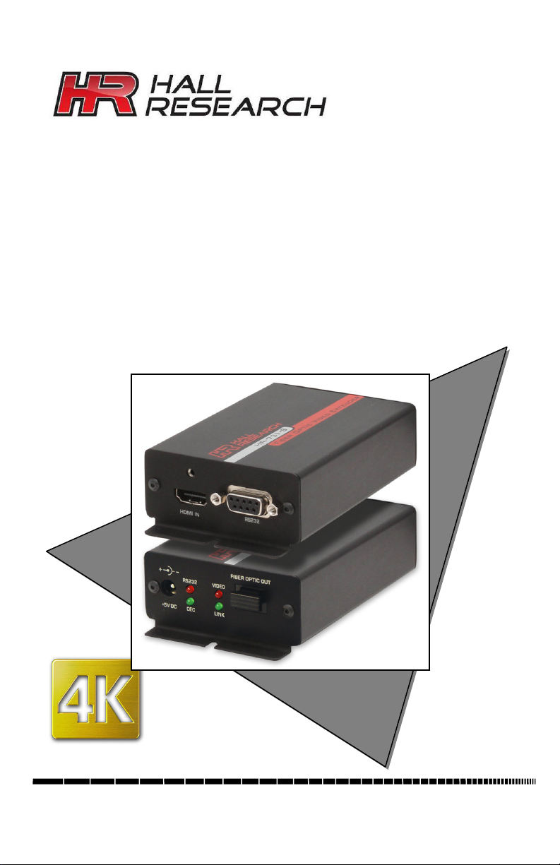
Figure 1 – Model HR-731-S
Sender Front and Rear
Page 5

HDMI and Serial over Single Fiber
3
This device is a Class 3R Laser device
This device is sensitive to Electrostatic
grounded.
2.0 Features
1 HDMI input
Transmits uncompressed HDMI video along with RS-232 to 1000m
Supports Deep-color (HDMI 1.3 or 1.4) and 3D
Compatible with DVI video (with DVI to HDMI input cable)
Status indication of fiber-optic link, Source video, RS232 or CEC
extension
Bi-directional RS-232 data transmission between the sender and the
receiver
RS-232 control of the data channel selection and setup
Safety interlock does not turn on high-power fiber LED drivers unless
fiber-optic cable is plugged in at both ends
Locking HDMI connectors
Green design, turns off parts of circuit when they are not in use
Compact, Rugged, Reliable, and Economical
Made in USA
3.0 Precautions
(per IEC 60825-1:2007) and can cause
damage to eye sight if used improperly.
Refer to ANSI Z136 for proper handling
and usage of Class 3R devices.
Discharge (ESD). Prior to touching the
unit (especially the connectors), touch a
grounded object, and make sure the
devices that will be plugged in to the
HR-731-S and HR-733-R are properly
Page 6

4
Model HR-731-S
4.0 Theory of Operation
The Sender HR-731-S provides an HDMI input with audio embedded in the
video on the same connector.
The video data is transmitted on only one multi-mode fiber. A multi-mode fiber
(rather than single mode) is required since the TMDS video data is transmitted
over a range of optical wavelengths to reduce bandwidth requirement at any
particular wavelength. The TMDS signals use LED lasers to drive the cable. For
safety reasons, these lasers are not turned on if no cable is plugged in at both the
Sender and Receiver.
Additional (non-video) hand-shake signals are also seamlessly connected
between the source and the sink device. These include:
• DDC Channel (SDAT and SCLK) for EDID and HDCP
• Hot Plug Detect (to detect remote monitor connection)
• Source Active +5vDDC (to indicate to sink there is a source)
In addition, the fiber-optic link provides a general purpose bi-directional data
lane that can be designated by the user to be either RS-232 pass-through or CEC
as defined by HDMI specifications. By default the HR-731 uses the data lane for
RS-232 control. Note that in CEC mode, the RS-232 connector on the Remote
does not serve any function but the RS-232 port on the Sender can still be used
for configuration changes.
5.0 Installation
HR-731 kit is comprised of a HR-731-S sender and a HR-733-R receiver.
The following block diagram depects an HR-733-S as a sender. The HR-731-S
only has one video input. The receiver is the same for both senders.
Figure 2 – Block Diagram (HR-731-S only has one HDMI video input)
Page 7

HDMI and Serial over Single Fiber
5
Data Rate
OM1
(62.5/125 µm )
OM2
(50/125 µm )
OM3
(50/125 µm )
(HDMI 1.2a)
5.1 Required Cables
• 1 HDMI cable to connect an HDMI source to the HR-731-S
• HDMI cable to connect the HR-733-R to the HDMI display
• RS-232 DB9 male-to-female (straight-through) cable to connect the
HR-731-S’s serial port to a PC
• Multi-mode (OM2 or OM3) fiber-optic cable
5.2 Fiber Optic Cable Requirements
Both the Sender HR-731-S and the Receiver HR733-R use a single SC connector and require a
multi-mode fiber-optic cable. The extender is not
compatible with single-mode cables. Multi-mode
cables are generally available in OM1, OM2, or
OM3 constructions. The OM3 cables are best
Figure 3
SC Fiber Connector
suited for max transmission lengths and are recommended for this product.
1.65 Gb/s
3.4 Gb/s
(HDMI 1.3, 1.4)
250 m (820 ft) 500 m (1640 ft) 1000 m (3280 ft)
150 m (500 ft) 250 m (820 ft) 500 m (1640 ft)
The above table shows the maximum possible cable lengths based on data rates
for 1080p resolution with normal 8-bit color, as well as 16 bit deep color per
HDMI 1.3 or 1.4, for different cable constructions.
5.3 Status of LED Indicators
LINK: ON – Optical link has been established between the sender and the receiver.
OFF
VIDEO: ON
OFF
CEC: ON
RS232: ON
– Optical link has not been established between the sender and the receiver.
– There is TMDS clock (digital video is coming from Source)
– Source is not outputting digital video.
– CEC mode is on. OFF – Not in CEC mode.
– RS-232 mode is on. OFF – Not in RS-232 mode.
Page 8

6
Model HR-731-S
6.0 Operation
The HR-731-S operates with a +5V power supply.
The HR-731-S has an input for HDMI source connection and a RS-232 port for
bi-directional data transmission between the Sender and the Receiver.
A fiber optic output connector is used to extend the HDMI signal to the Receiver
HR-733-R via a fiber optic cable up to 1000m.
The LINK LED will be on when there is an optic link between the Sender HR731-S and the Receiver HR-733-R. If no link is established between them, it will
be off.
The VIDEO LED will be on when there is a video source displayed on the sink
LCD.
The CEC and RS-232 LEDs are used to indicate the mode the data channel is set
to. By default they are in RS-232 mode. However, they can be switched to either
mode by sending a serial command ==>DCn<CR> to the Sender (see section
6.2).
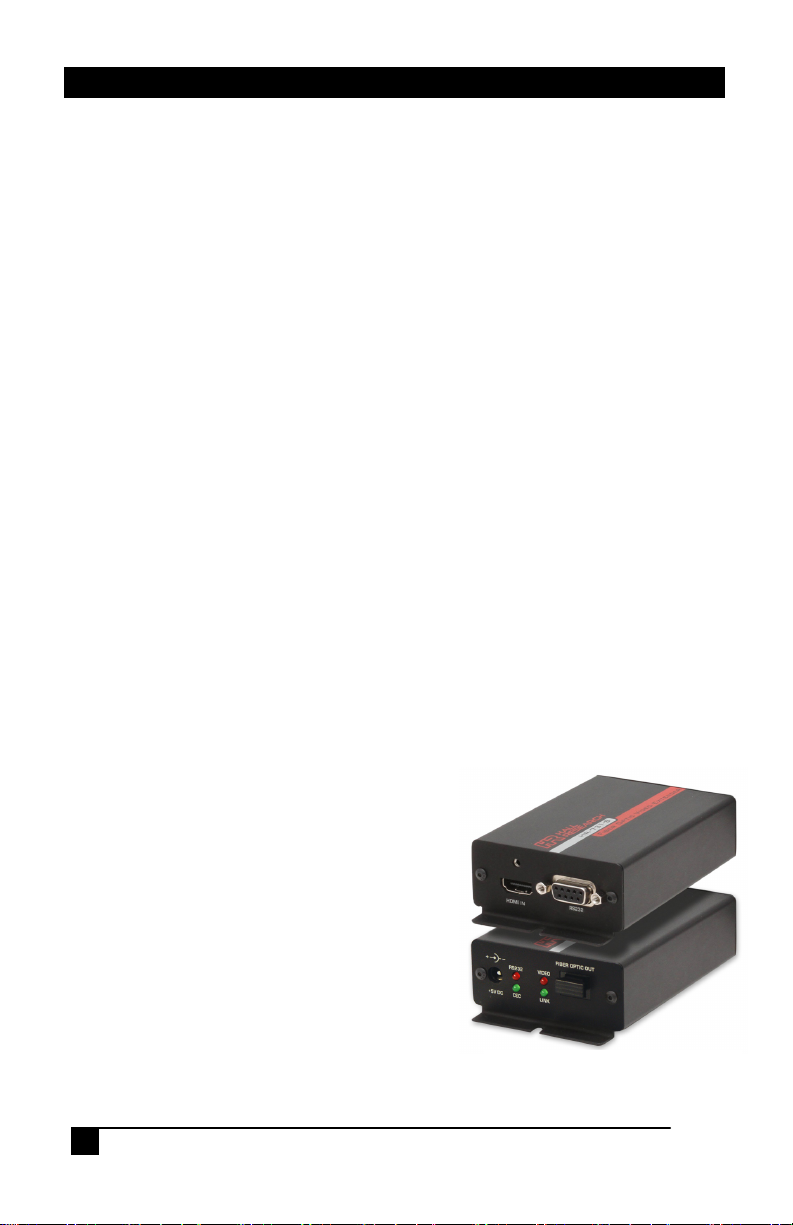
Figure 4 – HR-731-S Front and Rear Views
Figure 5 – HR-733-R Front and Rear Views
Page 9

HDMI and Serial over Single Fiber
7
DB9-Female on HR-731-S
DB9-Male on HR-733-R
3
RX (input)
3 TX (output)
NOTICE
6.1 More on RS-232
The RS-232 pin-out on the Sender and Receiver are shown below.
Pin Function Pin Function
2 TX (output) 2 RX (input)
5 Ground 5 Ground
The HR-731-S provides users the ability to set the mode of the data channel,
recall factory defaults, or change the remote receiver’s serial baud rate (and
parity).
The RS-232 port on the Sender operates at a fixed 9600 baud. The sender's baud
rate cannot be changed. As shipped the Receiver's baud rate is set at 19200,
however the receiver side's baud rate is user settable and can be set to any
standard rate in the range of 1200 to 115,200. Both sides incorporate data FIFOs
to accommodate the differing data rates at each end.
In a typical application, the remote receiver is connected to a display or a video
projector. In this case the RS-232 pass-through feature is used to control the
remote display (such as turning it on or off). Depending on the specification of
the remote display, the baud rate of the remote unit can vary. Through the serial
port in command mode, you can specify the remote unit’s serial parameters
(baud-rate and parity).
It is important to note that when sending configuration commands to
6.2 Using the HR-731-S in Command Mode
If the data received at the serial port contains ==> (equal, equal, greater than),
then the Sender will interpret it as start of a command sequence. In this mode
you can specify one of the commands described in the following section. The
unit will stay in command mode until it gets a Carriage Return <cr>. Once a
command is executed, the unit will go back to Serial pass-through mode (if data
channel is configured that way). The ==> and command sequence are not
transmitted to the HR-733-R remote unit.
Some commands can be issued to the HR-731-S regardless of how its data
channel is configured (CEC or RS-232 pass through). There are a few commands
that cannot be executed in CEC mode as noted below.
the Sender, the receiver must be connected and communicating.
Page 10

8
Model HR-731-S
6.3 RS-232 Control Commands
All commands are prefixed with ==>
All commands and responses are followed with a carriage return <CR>
Wrong commands will get a response of ERR1
Not-allowed commands in CEC mode will get a response of ERR2
Command: SBn stands for Set Baud of remote unit
Response: SBn
Condition: This command can only valid when the data channel is set to RS-232. If this
command is issued in CEC mode, the HR-731-S responds with ERR2
Command: SPn stands for Set Parity of remote unit
Response: SPn
Condition: This command can only valid when the data channel is set to RS-232. If this
command is issued in CEC mode, the HR-731-S responds with ERR2
Command: STn stands for Set Terminating byte/character
Response: STn
Condition: This command is only valid when the data channel is set to RS-232. If this
Comments: Normally in RS-232 mode, every character received is immediately
Command: DCn stands for Data Channel configuration
Response: DCn
Command: FD stands for Factory Default
Response: FD
Command: FW? stands for Firmware Version query
Response: FW Version #
command is issued in CEC mode, the HR-731-S responds with ERR2
transmitted to the opposite side. By specifying a Terminating character, the
device will keep all the data received in a buffer and transmit the entire
string at once upon receiving the terminating character (including the
terminating character). For example: to wait for a Carriage Return before
sending the string, use n=13 (since CR=0D Hex, or 13 Decimal).
where n=(0-7,?)
(0 = 1200, 1 = 2400, 2 = 4800, 3 = 9600, 4 = 19200, 5 = 38400,
6 = 57600, 7 = 115200, ? = query baud rate)
where n=(0-2,?)
(0 = none, 1 = odd, 2 = even, ? = query Parity)
where n=(0-255,?)
(0 = none (default), 1-255 = Terminating character (or byte) has
a decimal value of n , ? = query Terminating byte)
where n=(0,1,?)
(0 = RS-232, 1 = CEC, ? = query Parity)
Factory default settings will be restored
Page 11

HDMI and Serial over Single Fiber
9
7.0 Troubleshooting
Make sure that all of the connections to the units are solid, and check the state of
the LED’s on the front of the unit. Do not open or try to repair the unit yourself.
There is no customer repairable item in the unit and you will void your warranty.
Contact HR Support at 714-641-6607 or via email or web. If you need to ship
your unit for repair, make sure to get a Return Material Authorization (RMA)
number first.
8.0 Specifications
Video Inputs 1x HDMI or DVI
Supported
Resolutions HDTV from 480i to 1080p at any color depth, 4K30 8-bit
PC from VGA to WUXGA, 2560x1600@60 8bit color
Optical
Wavelength 780 nm to 980 nm
Optical
Cable Simplex (only 1 fiber) Multi-Mode. OM2 or OM3
Temperature Operating: 32 to 122°F (0 to 50°C);
Storage: –40 to +185°F (–40 to +85°C)
Enclosure Steel & Aluminum
MTBF 90,000 hours (calculated estimate)
Power 5V DC, 2.6A
Size (each) 1.25’’H x 2.75”W x 4.28”D (3.2x7.0x10.9 cm)
Weight (each) 0.4 pounds (0.18 kg)
Page 12

Page 13

© Copyright 2014. Hall Research, Inc.
All rights reserved.
1163 Warner Ave., Tustin, CA 92780
Ph: (714)641-6607, Fax: (714)641-6698
 Loading...