

Page 1
rraat
Hall Research, Inc
1163 Warner Ave.
Tustin, CA 92780
Phone: (714) 641-6607
Fax: (714) 641-6698
Oppee
O
• 1 Transmitter Unit with Power supply
• 1 Receiver Unit with Power supply
tiioonn IInnssttrruuccttiioonnss
P
C
V
i
d
e
o
&
A
u
d
i
o
T
r
a
n
s
m
i
s
s
i
o
n
S
y
s
t
e
m
P
C
V
i
d
e
o
&
A
u
d
i
o
T
r
a
n
s
m
i
s
s
i
o
n
S
y
e
s
S
y
s
P
C
V
i
d
e
o
&
A
u
d
i
o
T
r
a
n
s
m
i
s
s
i
o
n
O
v
e
r
O
O
S
i
n
g
l
e
F
i
b
S
i
n
g
l
S
e
i
n
g
l
e
e
F
i
b
e
F
i
b
e
v
e
r
v
e
r
r
O
p
t
i
c
C
a
b
l
r
O
p
t
i
c
r
O
p
C
t
i
c
C
e
a
b
l
e
a
b
l
UMA1047 Rev. C
t
e
m
t
e
m
Page 2

Page 3

PC Video & Audio Transmission System over Single Fiber Optic Cable
Table of Contents
TABLE OF CONTENTS .............................................................................................1
DESCRIPTION ............................................................................................................. 2
FEATURES .................................................................................................................... 3
HOW TO SETUP THE HR-722A .............................................................................. 4
FEDERAL COMMUNICATIONS COMMISSION STATEMENT................... 7
WARRANTY .................................................................................................................8
LIMITED LIABILITY................................................................................................. 8
1
Page 4

2
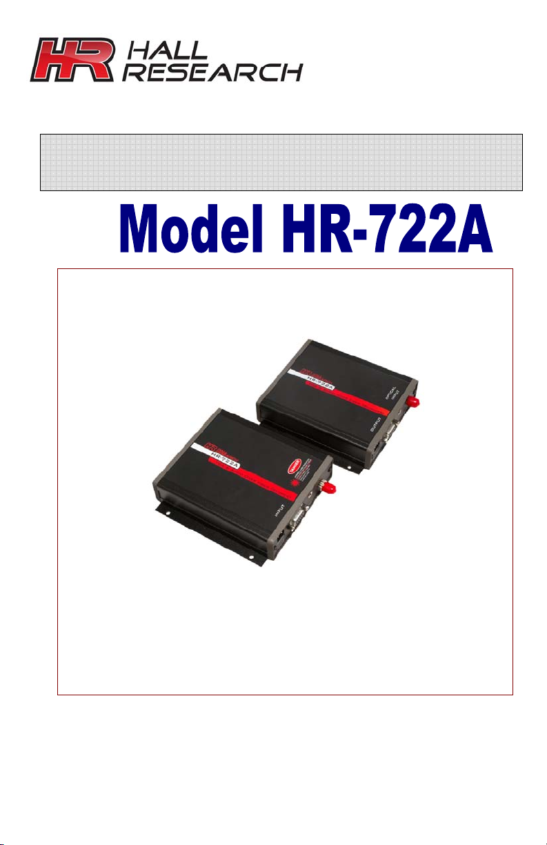
Model 722A
Description
The HR-722A Fiber Optic Communication System allows
direct connection of VGA computers for signal transmission
over Fiber Optic cable spanning distances to 2500 ft (0.75
kilometers) on multi-mode or 35 kilometers on single-
mode fiber (approximate based on loss budget). The HR722A features excellent picture quality with bright and sharp
images. Gone are the usual signal degradation and smearing
of coax or twisted pair video transmission at extended
lengths. Signal integrity is also maintained through fiber
optic cables' immunity to electrical interference and cross
talk. The lightweight and small diameter fiber reduces
installation time, particularly since only 1 fiber is needed.
Fiber optic cable also has certain intrinsic benefits for
installation success including resistance to electromagnetic
interference (EMI), lightning, and the elimination of ground
loops through electrical isolation.
The HR-722A Series includes the HR-722A-T Transmitter
and HR-722A-R Receiver, both with a 15 pin HD female
connector and 3.5 mm Stereo Audio jack. Power supplies
are also included in the package for the transmitter and the
receiver.
The system is generally used with standard Multimode Fiber
(62.5/125 um or 50/125 um) with common ST- connector
type. System integration allows all other Hall Research
Technologies, Inc. VGA compatible products to be used in
conjunction with the Fiber Optic system including
Distribution Amplifiers, Switches, and VGA Breakout Cables.
Page 5

3
PC Video & Audio Transmission System over Single Fiber Optic Cable
Features
1. Transmits VGA, SVGA, XGA and WXGA (640 x 480
up to 1366 x 768)
2. Supports HDTV resolutions of 480p, 720p and
1080i (RGBHV format only)
3. Uses all digital processing and transmission for
crystal clear signals and no color pixel skewing
4. Requires no adjustments, equalization or deskewing during installation
5. Transmits signals over one single mode or
multimode fiber optic core at 1310 nm
6. Virtually no audio/video skew
7. Ideal for digital signage, broadcast or corporate
studios, auditoriums, stadiums and theaters,
airport or transportation hubs, distance learning,
or medical imaging
8. Small, lightweight, low power
9. Use of Existing Fiber Lines
10. Elimination of Ground Loops
11. Secure Transmission for Tactical and Military
Installations
12. Immunity to Electromagnetic Interference
Page 6

4
Model 722A
How to setup the HR-722A
Notes:
• All units transmit at 1310 nm wavelength over single
mode or multimode fiber. ST connectors are
provided.
• Loss Budget and Maximum Transmission Distance:
Wavelength Loss Budget (in
dB)
1310 MM 0-15 0.75
1310 SM 0-15 35
* Distance specifications are only approximate and are not guaranteed.
Operating loss budget must not be exceeded
The HR-722 System is ready for immediate use. There are
LED indicators on the units for monitoring purposes. The
following instructions describe the typical installation
procedure and the function of the LED indicators.
1. Connect the video source to the video input HD-15F
connector on the transmitter unit.
2. Connect the video output on the receiver unit to the
HD-15F connector
3. Connect the fiber optic cable between the two units
4. Connect the audio input signals to
the transmitter stereo jack and the
audio output to the receiver stereo
jack.
5. Apply power to both units. Refer to
Figure 1.
6. When power is applied, the green POWER LED will
light, indicating the presence of operating power.
7. The system should now be operational.
Distance* (in
km)
Page 7

5
PC Video & Audio Transmission System over Single Fiber Optic Cable
Status of LED Indicators
TRANSMITTER:
Video: OFF: Indicates no video detected on the input.
BLINKING GREEN: Indicates either H or V sync
detected at the input but not both.
STEADY GREEN: Indicates both H and V sync
detected on the input.
Audio: OFF: Indicates no audio detected on the
transmitter unit.
BLINKING: Indicates audio detected on the
transmitter unit.
RECEIVER:
Video: OFF: Indicates no video detected over fiber
and, as a result, no video present on the
output.
BLINKING GREEN: Indicates either H or V sync
detected over the fiber but not both.
STEADY GREEN: Indicates both H and V sync
detected over fiber and, as a result, video
present on the output.
Audio: OFF: Indicates no audio detected over fiber
and, as a result, no active audio detected by
the receiver unit.
BLINKING: Indicates audio detected over fiber
and, as a result, active audio detected by the
receiver unit.
Page 8

6
Model 722A
SPECIFICATIONS
Video Specifications:
Number of Video Channels ............... 1 RGBHV
RGB Processing ............................... 24 bits, no compression or scaling
Input Impedance............................. RGB: 75 Ohms; H & V: Hi-Z
Input Level..................................... RGB: 714 mV p-p; H & V: 3 to 5 V p-p
H Sync Frequency Range .............…. 15 to 60 kHz
V Sync Frequency Range .............…. 30 to 85 Hz
RGB Format Supported .................… RGB with separate H and V
Audio Specifications:
Number of Audio Channels.............. 2, unbalanced
Frequency Response....................... +0/-0.5 dB, 20 Hz - 20 kHz
Bits-per-Sample/Sampling Rate ...…. 24 bits; 54 kHz
Maximum Audio Level...................... +10 dBu
SNR (A-Weighted)............................ 95 dB
Input Impedance.............................. >24 k Ohms
Output Impedance ........................... < 1 Ohm
Audio to Video Diff. Delay (skew) ...... <300 uSec
General Specifications:
Power Requirements....................... 9-24 v DC or AC, 5 watts
(Universal power supply is included)
Operating Temperature Range ......... -20 to +60 degrees C
Optical Connectors........................... ST
Operating Wavelength ...................... 1310 nm
Physical Size ..................................... 5 W x 1.15 H x 5.25 L (inches)
Weight ............................................. approx. 10 oz.; 0.284 kg
Page 9

PC Video & Audio Transmission System over Single Fiber Optic Cable
Federal Communications Commission
Statement
This equipment generates; uses and radiates radio
frequency energy and, if not installed and used in
accordance with the instructions, may cause harmful
interference to radio communications. This equipment has
been tested and found to comply with the limits for a Class A
computing device, pursuant to Part 15 of the FCC rules.
Harmful interference when operated in a commercial
environment. Operation of this equipment in a residential
area is likely to cause interference, in which case the user,
at his own expense, will be required to take whatever
measures are necessary to correct the interference.
If necessary, you should consult the place of purchase or
and experienced radio/television technician for additional
suggestions.
7
Page 10

8
Model 722A
Warranty
Hall Research warrants that the supplied equipment is free
from defective workmanship and material. Subject to the
agreements set forth, will repair or replace, at its option, the
defective components for a period of 2 years after purchase.
The following conditions apply to the Warranty:
Warranty void if item subject to improper use, negligence,
or unauthorized modification
Instructions must be followed in obtaining RMA number as
explained below
Any defective part should be returned, insured and freight
prepaid, to Hall Research, with the following:
• Return Material Authorization Number (RMA#)
• Description of failure, as detailed as possible
• Shipping address and contact name and phone
number
Limited Liability
IN NO EVENT SHALL THE DIRECT VENDOR'S LIABILITY
EXCEED THE PRICE PAID FOR THE PRODUCT FROM DIRECT,
INDIRECT, SPECIAL INCIDENTAL OR CONSEQUENTIAL
DAMAGES RESULTING FROM THE USE OF THE PRODUCT OR
ITS DOCUMENTATION
Page 11

Page 12

Made in the USA
© Copyright 2010. Hall Research, Inc.
All rights reserved.
1163 Warner Ave., Tustin, CA 92780
Ph: (714) 641-6607, Fax: (714) 641-6698
 Loading...