

Page 1
UMA1201 Rev. D
GUI Insert
CUSTOMER
Software GUI User’s Manual
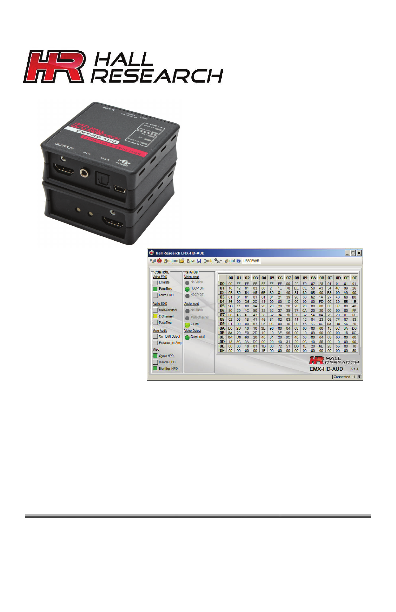
AUDIO EXTRACTOR & EDID MGR GUI
Model EMX-HD-AUD
SUPPORT
INFORMATION
Order toll-free in the U.S. 800-959-6439
FREE technical support, Call 714-641-6607 or fax 714-641-6698
Address: Hall Research, 1163 Warner Ave. Tustin, CA 92780
Web site: www.hallresearch.com E-mail: info@hallresearch.com
Page 2

Page 3

1
MODEL EMX-HD-AUD AUDIO EXTRACTOR & EDID MGR
1. EMX-HD-AUD Windows™ Software Installation
1.1. General
The EMX-HD-AUD is controllable via a free Windows® based.
All of the device features, and more, are accessible from the GUI. EDID files can be
exported or imported. The device is also capable of writing custom EDID data back
to compatible display devices.
1.2. Software Installation Prerequisites
• A PC with Windows XP® OS or later
• USB port
• Microsoft® .NET Framework 2.0 or later (most recent OS including
Windows 7 and 8 typically include this and no action is required). If.NET
Framework 2.0 or later is not installed on your PC, the Microsoft™ website
has free downloads available.
1.3. Software Installation
If an earlier version of this particular software was previously installed,
UNINSTALL the program first from either the Add/Remove Programs section of
the control panel or by running the previous installation’s SETUP.EXE and
selecting “remove application”.
• Install the software by executing the SETUP.EXE program from the
installation source directory
• Accept the default settings, but if you want to specify a particular
installation directory other than the default, you may do so.
• Once the VR-DVI software installation has completed, either click the
desktop icon or navigate the Start Menu to
Start -> Programs -> Hall Research -> EMX-HD-AUD Audio Extractor
1
Page 4
2
User’s Manual
This detection and auto installation only occurs once. Thereafter,
2. Using the Software
2.1. General
In most installations the use of the
software is not needed as most
functions can be performed using
the push-buttons on the product as
described in the previous section.
You can use the software to
import/export EDID files from the
device. Custom EDID data can also be written to devices connected to the
output if they support that function. You can also mute the extracted audio, or
remove the audio from the HDMI output.
It is possible to connect more than one EMX-HD-AUD to the PC (using several
USB ports of the PC). The same instance of the software detects all connected
devices and allows control from the same interface.
2.2. USB Device Detection
The EMX-HD-AUD software uses standard Windows® drivers to automatically
configure the USB port after connection and does not require any special USB
drivers to be installed.
The first time you connect the extender to the PC, you may experience a short
delay and a windows notification pop-up message may be shown.
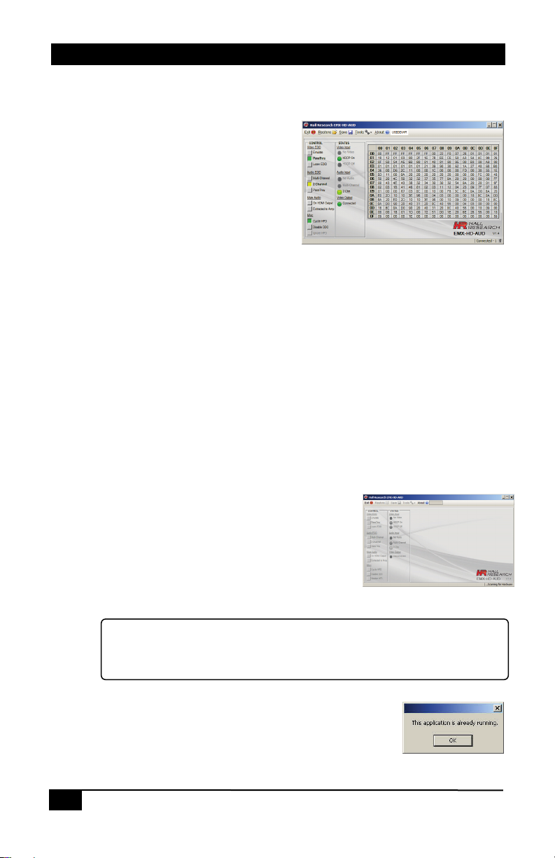
2.2.1. The software scans the EMX-HD-AUD
settings continuously in real time, so all
changes are immediately reflected on the
screen
2.2.2. If no EMX-HD-AUD device is attached to
the system, the on-screen fields are
disabled (grayed out)
reconnected devices are detected with no delay or message.
2.2.3. Only one instance of the GUI program can run at
a time. Executing the application more than once
will result in an error message.
2
Page 5

3
MODEL EMX-HD-AUD AUDIO EXTRACTOR & EDID MGR
2.3. Tool Bar Menu
2.3.1. RESTORE
Restore device settings from file
Used to select previously saved files
2.3.2. SAVE
Save device settings to a file
Save file to any location on the PC.
2.3.3. TOOLS
Factory Defaults
Restore the device to factory default settings.
The user must confirm the action.
Import EDID
Import an EDID (256-byte binary or XML file) into the unit.
Export EDID
Save the current EDID as a 256-byte binary file
This file can be edited using third party software and reloaded using the
‘Import EDID’ tool selection.
Write EDID
Writes the current 256-byte EDID to the currently
connected output device. This option is not available
on systems with older firmware.
The user must confirm the action and take all necessary precautions to
prevent loss of data. Hall Research is not responsible for any damage that
may occur from the user attempting to modify the EDID.
Firmware Update
Allows users to field upgrade the device application firmware. Application
firmware that does not support this function will disable this option. Only
valid firmware files can upload into the EMX-HD-AUD.
2.3.4. EXIT
Exits the application
3
Page 6

4
User’s Manual
2.3.5. ABOUT
Displays screen with software versions,
website link, legal disclaimer and copyright
information. The Serial # information
displayed is a time/date stamp referenced to
GMT (Greenwich Mean Time) and has no
reference to the serial number sticker on the actual device.
2.4. Device Name
Assigns a descriptive name to the EMX-HD-AUD device that
is a maximum 8 characters long. The user is not allowed to
change the device name with multiple devices connected.
The FACTORY DEFAULT name is USBDEVHR.
2.5. Status Bar
The bottom bar of the screen shows the current USB status as follows:
“Scanning for Hardware…”
The GUI software is looking for EMX-HD-AUD devices.
Screen controls disable until a valid EMX-HD-AUD device
attached
“Connected – XX”
Where XX is the number of EMX-HD-AUD devices connected to the
PC.
2.6. CONTROL Group
VIDEO EDID
Clicking these controls selects to either PASS-THRU or
EMULATE the EDID.
PASS-THRU uses the SINK EDID while EMULATE uses the
internal EDID saved in the EMX-HD-AUD.
PASS-THRU is the FACTORY DEFAULT setting.
Learn EDID
Clicking this control will extract the EDID from device
connected to the output connector and save it in the unit.
The user must confirm the action.
4
Page 7

5
MODEL EMX-HD-AUD AUDIO EXTRACTOR & EDID MGR
AUDIO EDID
Clicking these controls selects either PASS-THRU, 2 CHN or
MULTI modes
MULTI – EDID from SINK is set for LPCM, DTS and Dolby
audio with multiple speakers.
2 CHN – EDID from SINK is set for 2 channel LPCM audio with 2 speakers.
This is the FACTORY DEFAULT setting.
PASS-THRU – EDID from SINK is used.
Mute Audio
On HDMI Output
Clicking this control mutes the HDMI Audio.
FACTORY DEFAULT is not muted.
Extracted to Amp
Clicking this control mutes the 3.5mm L/R and TOSLINK Audio.
FACTORY DEFAULT is not muted.
Misc
Cycle HPD
Clicking this control sends a 500 mS Hot Plug Detect signal to
the video source. This indicator is ‘filled’ when the source is
connected.
Disable/Enable DDC
Disabling this control will turn off the DDC communication with the SOURCE
device. The SOURCE will receive no response from any HDMI or EDID
requests. This effectively disables the SOURCE from displaying HDCP content.
FACTORY DEFAULT is enabled (HDCP and EDID acceptable).
Monitor/Ignore HPD
Clicking this control to ‘Ignore HPD’, allows the source to ignore changes to the
OUTPUT HPD line.
The default behavior is to restart the HDMI/HDCP communications to the
SOURCE if a SINK device reconnects after becoming disconnected.
This re-initializing of the connection to the source may cause a momentary
drop-out in the Video and Audio output.
If this selection is set to "ignore" HPD, then the signal from the source is
uninterrupted.
FACTORY DEFAULT is to monitor the SINK HPD.
5
Page 8

6
User’s Manual
NOTE
2.7. STATUS
Video Input
No Video
Indicates the system is not receiving an INPUT video
signal.
HDCP On
Indicates video received has HDCP Encryption enabled.
HDCP Off
Indicates video received has HDCP Encryption disabled.
Audio Input
No Audio
Indicates no audio received (DVI mode)
Multi-Channel
Indicates HDMI audio received is not LPCM format.
2 Chn
Indicates HDMI audio received is LPCM format.
Video Output
Connected or Disconnected
Indicates the state of the device connected to the EMXHD-AUD OUTPUT. When a display is detected the button
will be green and the word Connected will be shown next to it. When no
display is detected (or the display is not sending an HPD signal), then the
indicator on the screen changes to a dark red color and the word
Disconnected will be shown next to it.
2.8. EDID Data Display
The data shown in the EDID table is continually
scanned to ensure that the checksums for each
block is valid.
6
When wrong checksums are detected, the
invalid checksum byte is highlighted in RED.
If an action is performed that affects the EDID such as initiating a "learn"
process, The checksum field might momentarily flash ‘RED’ during the this
process, but should go back to normal once the entire table is updated.
You cannot “LEARN” an EDID that has an invalid checksum. If you try to learn an EDID that has a
checksum error, the PASS-THRU and EMULATE LEDs on the unit will alternately flash 5 times to
indicate the error.
No other checks are performed on the EDID to determine that it is valid per the EDID standard.
However the GUI software can import and upload to the EMX-HD-AUD, EDID’s that contain invalid
checksum for testing purposes.
Page 9

7
MODEL EMX-HD-AUD AUDIO EXTRACTOR & EDID MGR
VIDEO MODE
AUDIO MODE
EDID EFFECT
2.9. EDID Mixing
First of all, it is important to understand that any display device only has one
EDID table that has information on all of its video and audio capabilities. The
EMX-HD-AUD gives the user the capability to independently control or alter the
video and audio portions of the EDID. This process is called EDID mixing. At
power up, the default EDID stored within the device is loaded. This could be
either the factory default or a ‘Learned’ EDID.
If a functioning and valid SINK device is connected to the EMX-HD-AUD
‘Output’ connector and the VIDEO EDID mode is set to PASS-THRU, the EDID
from the SINK will be read and loaded into memory.
If the SINK EDID read is a simple 128 byte EDID (like some DVI monitors), a
CEA-861 extension block (2nd 128 bytes) will be added to the EDID with a
default native resolution of 480p and with LPCM 2 channel audio.
If the SINK is disconnected from the VSA-HA-DP connector, the internally
saved EDID will be presented to the SOURCE mixed according to the AUDIO
settings. Each time the VIDEO or AUDIO EDID GUI controls are pressed, the
EDID presented to the SOURCE would be as shown in the following table:
PASS PASS SINK EDID PASSED WITH CEC ADDRESS MODIFICATION
PASS 2CHN SINK EDID PASSED WITH 2CHN AUDIO AND CEC
PASS MULTI SINK EDID PASSED WITH 2CHN, DTS AND DOLBY AUDIO
EM PASS NOT POSSIBLE
EM 2CHN INTERNAL EDID PASSED WITH 2CHN AUDIO AND CEC
EM MULTI INTERNAL EDID PASSED WITH 2CHN, DTS AND DOLBY
ADDRESS MODIFICATION
AND CEC ADDRESS MODIFICATION
ADDRESS MODIFICATION
AUDIO AND CEC ADDRESS MODIFICATION
2.10. CEC Physical Addressing
CEC Address modification consists of taking the SINK or INTERNAL EDID and
modifying the address to insert the EMX-HD-AUD CEC Physical address into
the CEC chain. (The EMX-HD-AUD device does not understand any CEC
commands).
For example: SINK EDID has CEC address of 0.0.0.0
EDID given to source will show the EMX-HD-AUD as CEC address 1.0.0.0 and
the display still with its original CEC address of 0.0.0.0
7
Page 10

8
User’s Manual
8
Page 11

Page 12

Order toll-free in the U.S. 800-959-6439
CUSTOMER
SUPPORT
INFORMATION
© Copyright 2014 Hall Research, Inc.
All rights reserved.
FREE technical support, Call 714-641-6607 or fax 714-641-6698
Mail order: Hall Research, 1163 Warner Ave. Tustin, CA 92780
Web site: www.hallresearch.com E-mail: info@hallresearch.com
 Loading...