

Page 1
H
H
aallll
R
eesseeaarrcchh
R
T
eecchhnnoollooggiieess,, IInncc..
T
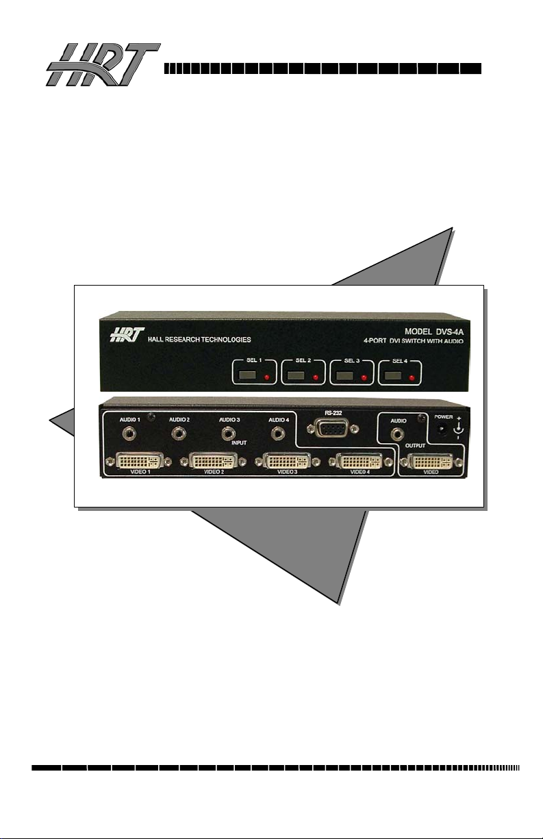
Model DVS-4A
4-Port DVI Switch with Audio, Serial Control &
Long Cable Equalization
UMA1129
Rev B
© Copyright 2007. Hall Research Technologies, Inc. All rights
1163 Warner Ave Tustin, CA 92780, Ph: (714)641-6607, Fax -6698
Page 2

Page 3

4-Port DVI Switch with Audio & Serial Control
Trademarks Used In this Manual
Hall Research, HRT, and (logo) are trademarks of Hall Research
Technologies, Inc. Any other trademarks mentioned in this manual are
acknowledged to be the property of the trademark owners.
Federal Communications Commission Statement
This equipment generates uses and radiates radio frequency energy and, if
not installed and used in accordance with the instructions, may cause
harmful interference to radio communications. This equipment has been
tested and found to comply with the limits for a Class A computing
device, pursuant to Part 15 of the FCC rules. These limits are designed to
provide reasonable protection against harmful interference when operated
in a commercial environment. Operation of this equipment in a residential
area may cause interference, in which case the user, at their own expense;
will be required to take whatever measures are necessary to correct the
interference.
European Union Declaration of Conformity
This product has been tested and shown to comply with the
requirements of the European EMC directive 89/336/EEC.
1
Page 4

Table of Contents
4-Port DVI Switch with Audio & Serial Control
1.0 General ................................................................................................ 3
2.0 Features................................................................................................ 4
3.0 Installation ........................................................................................... 5
. Required Cables..................................................................................... 5
. Inputs & Outputs ................................................................................... 5
. Connecting the DVS-4A........................................................................ 5
. Connection Diagram.............................................................................. 6
4.0 Operation ............................................................................................. 7
. Manually Switched Output .................................................................... 7
. Modes of Operation ............................................................................... 7
. Priority Selection in Auto Mode............................................................ 8
. Long Cable Equalization ....................................................................... 8
. Scan Mode ............................................................................................. 8
. RS-232 Control Port Usage ................................................................... 9
. To configure HyperTerminal................................................................. 9
. Serial Port Control Codes .................................................................... 10
5.0 Troubleshooting................................................................................. 16
6.0 Specifications..................................................................................... 17
2
Page 5

4-Port DVI Switch with Audio & Serial Control
1.0 General
Thank you for purchasing Hall Research Technologies’ DVS-4A 4-Port
DVI Switch with Audio & Serial Control.
This unit provides both a video and audio output that can be switched
between four video and audio sources. This allows routing of multiple
DVI equipped devices (such as PC’s) to a single DVI display (such as a
plasma or LCD screen). The switcher supports single-link, DVI-D video
signals at resolutions up to 1920x1200 and HDTV up to 1080p.
The DVS-4A unit provides all the A/V and control connections on the
rear panel; the front panel has a push-button switch with corresponding
LED indicator for the selection of video source.
This unit can be controlled by either manually
switch, automatically
RS232 serial port.
The unit can be configured to operate in three different modes, which are
the Auto, Scan and Manual modes.
The unit also has EEPROM (internal non-volatile flash memory) to store
the last operating mode when power is off.
based on video detection, or remotely through an
using the front panel
3
Page 6

4-Port DVI Switch with Audio & Serial Control
2.0 Features
9 Clear and sharp images at resolutions up to 1920x1200 including
HDTV up to 1080p
9 Hot pluggable
9 Supports the DDC2 standard for all input ports
9 HDCP & HDMI 1.3 Compatible
9 Allows one video with stereo audio to be switched between four
video and audio sources
9 Can be manually controlled by push-button switches, remotely by a
RS232 communication port
9 Provides an Auto mode to automatically select input source
9 Auto Mode priority can be set for any input or no-priority
9 Scan Mode shows each output for a programmable time period
9 Switched output can be blanked and un-blanked
9 Video Cable Equalization available for long cabling
9 Stores the last selection and mode in EEPROM
9 Compatible with the Universal Mounting Bracket
9 Ships with universal (100~240 VAC) power supply
9 Compact, Rugged, Reliable, and Economical
9 Made in USA
4
Page 7

4-Port DVI Switch with Audio & Serial Control
3.0 Installation
. Required Cables
The video input cables are generally DVI male to male (customer
furnished). The Audio inputs are 3.5 mm mini-stereo (customer
furnished). To connect to the unit to a Serial port (such as PC’s COM1)
you would need a Male/Female DB9 Serial Cable (customer furnished).
All of these items are available for purchase upon request.
. Inputs & Outputs
The DVS-4A has 4 video and audio inputs labeled ‘Video 1’ through
‘Video 4’. The unit has 1 video and audio output labeled ‘Video Output’.
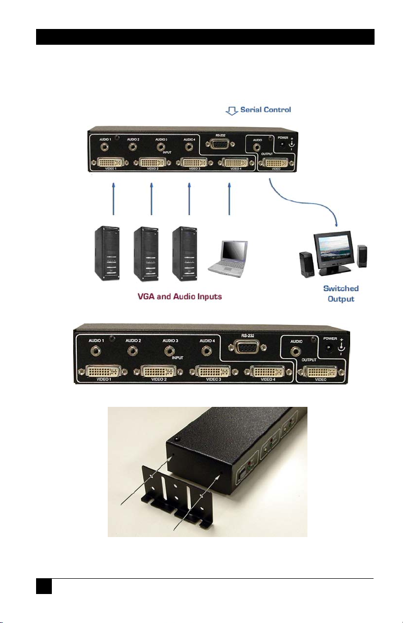
. Connecting the DVS-4A
Connect your video and audio sources such as computer or notebook PC
to ‘Video 1’, ‘Video 2’, ‘Video 3’ and/or ‘Video 4’ connector(s).
Connect the display device such as a monitor (or a video projector) to the
switched video and audio output connectors.
Connect the included power supply to the DVS-4A.
Select the desired mode of operation (Auto, Scan or Manual) using the
front panel switched buttons. (Auto = SEL 1 & SEL 2, Scan = SEL 3 &
SEL 4)
If preferred, the above selections (and more) can also be done through
RS-232 serial commands by connecting a DB9 RS-232 Serial cable to
your PC and the DVS-4A.
The device can be mounted via a Universal Mounting Bracket (sold
separately) if desired.
5
Page 8
4-Port DVI Switch with Audio & Serial Control
. Connection Diagram
MODEL DVS-4A REAR PANEL
Universal Mounting Bracket
6
Page 9

4-Port DVI Switch with Audio & Serial Control
4.0 Operation
. Manually Switched Output
The SEL1 through SEL 4 buttons are used to select between video &
audio input sources of Video 1 through Video 4. A solid-on LED is used
to indicate which input is selected.
Holding down any of the SEL buttons for 3 seconds will blank that
selected input source (and mute the audio output). The LED for that
selected input will start blinking to indicate the blanking mode. Pressing
that SEL button again will un-blank the output and un-mute the audio on
the Video Output rear connector.
MODEL DVS-4A FRONT PANEL
. Modes of Operation
The unit can operate in either Auto or Manual mode. Pressing the SEL 1
and SEL 2 buttons simultaneously for 3 seconds will select AUTO mode.
Pressing any SEL button selects MANUAL mode.
When in Auto mode, the SEL 1 and SEL 2 LEDs will flash to indicate the
mode is active.
In Auto
video and audio. The presence of video is determined by examining the
V. Sync signal or optionally the +5 VDC signal from DVI input
connectors. The front panel SEL buttons cannot be used to switch
between ‘Video 1’ through ‘Video 4’ sources in this mode. Pressing any
of the SEL buttons will take the unit out of AUTO mode.
In Manual mode, the output of the DVS-4A will depend on the selection
of the SEL buttons.
mode, the DVS-4A will automatically select the input with active
7
Page 10

4-Port DVI Switch with Audio & Serial Control
. Priority Selection in Auto Mode
The priority of the Video 1 through Video 4 inputs can only be selected
by a command through the RS232 port.
This priority selection only applies to Auto
selected, the DVS-4A will automatically select that ‘Video' input
whenever it detects the presence of a video signal at that ‘Video’
connector, regardless of what is happening at the other ‘Video’
connectors. A priority value can be set for all four ‘Video’ input
connectors.
For example, the priority has been set for ‘Video 2’, ‘Video 4’, ‘Video 1’
and then ‘Video 3’. If the ‘Output’ is playing the video & audio from
‘Video 3’ and video from ‘Video 1’ is detected, the output of the DVS-4A
will change to select ‘Video 1’ video immediately. Video detection on
either ‘Video 2’ or ‘Video 4’ would take precedence over the ‘Video 3’
signal.
mode. If a video priority is
. Long Cable Equalization
The use of long DVI cables can cause the ‘Video’ image to degrade to
unacceptable levels. Enabling the ‘BOOST’ signal, can sometimes
compensate for the cable length and produce an acceptable picture.
The ‘BOOST’ setting can only be selected by a command through the
RS232 port.
. Scan Mode
The unit can operate in Scan Mode by pressing the SEL 3 and SEL 4
buttons simultaneously for 3 seconds.
When in Scan mode, the SEL 3 and SEL 4 LEDs will flash to indicate the
mode is active.
In scanning mode, the unit will display each of the video and audio input
signals for a pre-determined time period from 1 to 60 seconds.
The unit can also be programmed (via the RS232 port) to scan only
active video inputs or even inputs without a video signal.
8
Page 11

4-Port DVI Switch with Audio & Serial Control
. RS-232 Control Port Usage
The DVS-4A can also be controlled via a serial device. The unit operates
at a baud rate of 4800 bps. From the serial port, you have full control
over the operation of the switched output, mode, and priority buttons.
Note on the RS-232 port availability on your PC
Most PCs and notebooks do not have a
serial port. So to program the Switch you
may need a USB to RS-232 Serial
converter. These are available from Hall
Research Technologies (Model USBRS232-1).
The DVS-4A will output a menu to the serial port on power-up. This
menu can also be displayed when the appropriate command is sent to the
DVS-4A via the serial port. To view the menu, an ASCII serial terminal
or terminal emulator software is needed. An example is Microsoft
Windows HyperTerminal (generally found in the Accessories ->
Communication folder)
. To configure HyperTerminal
- Connect direct to any available COM port
- 4800 Baud, 8 bits, No Parity, 1 Stop bit, No flow control
- Settings per following figures:
9
Page 12

After power-up the unit will output the following menu in ASCII through
its serial port:
4-Port DVI Switch with Audio & Serial Control
MENU - Version 1.0
---------------------------------------- 1 = Video 1 Input | B = Blank
2 = Video 2 Input | U = Un-blank
3 = Video 3 Input | E = Enable boost
4 = Video 4 Input | D = Disable boost
A = Auto mode | R = Report
S = Scan mode | F = Factory defaults
P = Priority | M = Menu
-----------------------------------------
. Serial Port Control Codes
Control codes are 1 byte commands from an external device to the Serial
Port on the DVS-4A.
ASCII ‘1’ (Hex 31 or Decimal 49)
Selects Video input #1 (immediately and unconditionally).
If the unit was in AUTO mode, then MANUAL mode is
selected.
The device will respond with: Video 1 selected
ASCII ‘2’ (Hex 32 or Decimal 50)
Selects Video input #2 (immediately and unconditionally).
If the unit was in AUTO mode, then MANUAL mode is
selected.
The device will respond with: Video 2 selected
ASCII ‘3’ (Hex 33 or Decimal 51)
Selects Video input #3 (immediately and unconditionally).
If the unit was in AUTO mode, then MANUAL mode is
selected.
The device will respond with: Video 3 selected
10
Page 13

4-Port DVI Switch with Audio & Serial Control
ASCII ‘4’ (Hex 34 or Decimal 52)
Selects Video input #4 (immediately and unconditionally).
If the unit was in AUTO mode, then MANUAL mode is
selected.
The device will respond with: Video 4 selected
ASCII ‘A’ or ‘a’ (Hex 41/61 or Decimal 65/97)
Enters Auto mode.
If the unit was already in AUTO mode, the unit will
respond with the message:
Auto mode already selected
If the unit was in MANUAL mode, the user must select the
desired detection method by entering a number from 1 to
3 within 20 seconds. Values outside this range or delaying
entry longer than 20 seconds will result in an error
message: Invalid entry! Current detection stays the
same.
The device will respond with:
Auto mode selected
Detection Method
---------------------------- 1 = Vertical sync
2 = 5V Power
3 = Vertical sync & 5V power
---------------------------- Current detection is [3] (1-3)?
In Auto mode, the device automatically switches to the video
& audio input source that is active.
“Active” means that video signal has sync signal, it does not
mean there is a non-static screen!
11
Page 14

4-Port DVI Switch with Audio & Serial Control
ASCII ‘P’ or ‘p’ (Hex 50/70 or Decimal 80/112)
Selects the Video Input priority.
A message is displayed in the format of:
Video X priority is [Y] (1-4]?
Where ‘X’ is the video input (1-4) and ‘Y’ is the current
priority (1-4).
The user must respond within 20 seconds and with values
in the range of 1-4 or the error message:
Invalid input! Please select ‘Priority’ again
will be displayed.
If ‘0’ is input, the message No change was made will be
displayed.
If the priority values are set to equal values, the first input
with an active Video signal will be displayed.
ASCII ‘B’ or ‘b’ (Hex 42/62 or Decimal 66/98)
Blanks the output.
The device will respond with: Blank mode selected
When the output is blanked, only the color intensities of the
output are reduced to zero. The unit still operates in a normal
fashion and sync signals are still routed to the output. The
audio output is muted.
ASCII ‘U’ or ‘u’ (Hex 55/75 or Decimal 85/117)
Un-blanks the output.
The device will respond with: Unblank mode selected
ASCII ‘E’ or ‘e’ (Hex 45/65 or Decimal 69/101)
Causes the output signal equalization for long cabling to be
enabled.
The device will respond with: Boost enabled
12
Page 15

4-Port DVI Switch with Audio & Serial Control
ASCII ‘D’ or‘d’ (Hex 44/64 or Decimal 68/100)
Causes the output signal equalization for long cabling to be
disabled.
The device will respond with: Boost disabled
ASCII ‘R’ or ‘r’ (Hex 52/72 or Decimal 82/114)
Request the status report. The device will respond with:
Report
------------------ Input = Video 1 (or 2,3,4)
Output = No LCD (or LCD Present)
Mode = Manual (or Auto)
Video 1 priority is [1] (or 2,3,4)
Video 2 priority is [2] (or 2,3,4)
Video 3 priority is [3] (or 2,3,4)
Video 4 priority is [4] (or 2,3,4)
Scan time (sec) = 5 (or 1 to 60)
Scan video = Active only (or All)
Blank = Off (or On)
Boost = Disabled (or Enabled)
Detection method = Vertical sync & 5V power
(or either one only)
This report displays the current settings of the Input, Output,
Mode, Priority, Scan, Blanking and Video detection method.
13
Page 16

4-Port DVI Switch with Audio & Serial Control
ASCII ‘S’ or ‘s’ (Hex 53/73 or Decimal 83/115 )
Enters Scan Mode
If the unit was already in SCAN mode, the unit will respond
with the message:
Scan mode already selected
The user must select the desired scan time by entering a
number from 1 to 60 within 20 seconds. Entries outside
this range or delaying entry longer than 20 seconds will
result in a default setting of 5 seconds.
The device will respond with:
Scan mode selected
Please enter ‘time between switching’ (1-60 sec):
After the entry (or timeout), the device will respond with:
Scan non-active video? (y/n)’
Again the user must respond within 20 seconds.
Entries other than ‘Y’, ‘y’, ‘N’ or ‘n’ or delaying entry longer
than 20 seconds will result in an error message
corresponding to the last setting of the SCAN mode.
Invalid input! Scan only active video
Invalid input! Scan all video
In scan mode, the unit will display each of the video and audio
inputs for the selected time period. If the device was told to
scan non-active video inputs and no video is available on that
input, a black screen will be displayed for the selected time
period.
14
Page 17

4-Port DVI Switch with Audio & Serial Control
ASCII ‘M’ or ‘m’ (Hex 4D/6d or Decimal 77/109)
Displays the menu. The device will respond with:
MENU - Version 1.0
---------------------------------------- 1 = Video 1 Input | B = Blank
2 = Video 2 Input | U = Un-blank
3 = Video 3 Input | E = Enable boost
4 = Video 4 Input | D = Disable boost
A = Auto mode | R = Report
S = Scan mode | F = Factory defaults
P = Priority | M = Menu
-----------------------------------------
ASCII ‘F’ or ‘f’ (Hex 46/66 or Decimal 70/102)
Causes the system to be reset to its DEFAULT factory
settings.
The device will respond with: Factory defaults restored
ASCII ‘v’ (Hex 76 or Decimal 118)
Causes the system to display the firmware version number.
The device will respond with:
Firmware Version: X.Y where ‘X.Y’ is the numeric
version level of the firmware software.
15
Page 18

4-Port DVI Switch with Audio & Serial Control
5.0 Troubleshooting
Make sure that all your connections are solid, and check the state of the
LED’s on the front of the unit.
Do not open or try to repair the unit yourself. There is no customer
repairable item in the unit and you will void your warranty. Contact HRT
Support at 714-641-6607 or via email or web. If you need to ship your
switch for repair, make sure to get a Return Material Authorization
(RMA) number first.
Cable Length Limitations
The switcher cannot be used as an extender. Therefore it is best to plug
the output of the switch directly to the display device and use input cables
that are 5 meters (16 ft) maximum. In other words, try to keep the total
length of cables from the video source to the box and from the box to the
monitor should not exceed 16 feet. At longer distances you may
experience video degradation. If you cannot use shorter cables, try to set
the refresh rate and/or resolution of the video signal to a lower level.
16
Page 19

4-Port DVI Switch with Audio & Serial Control
6.0 Specifications
Video Inputs DVI-D Single Link, HDCP & HDMI 1.3 Compliant
Resolutions PC resolutions up to 1920x1200 @ 60 Hz and HDTV to
1080p
Audio Inputs PC audio outputs
Temperature Operating: 32 to 122°F (0 to 50°C);
Storage: –40 to +185°F (–40 to +85°C)
Enclosure Steel
MTBF 90,000 hours (calculated estimate)
Power 6V center positive via supplied Universal power supply
Size 1.66" High x 8.42" Wide x 2.61” Deep
Weight 2.0 pounds
DVI Connector pin out N/U = Not Used
Pin Signal name Pin Signal name
1 TMDS Data2– 13 TMDS Data3+ (N/U)
2 TMDS Data2+ 14 +5V Power
3 TMDS Data2/4 Shield 15 Ground for +5V Power
4 TMDS Data4– (N/U) 16 Hot Plug Detect
5 TMDS Data4+ (N/U) 17 TMDS Data0–
6 DDC Clock 18 TMDS Data0+
7 DDC Data 19 TMDS Data0/5 Shield
8 Analog vertical sync 20 TMDS Data5– (N/U)
9 TMDS Data1– 21 TMDS Data5+ (N/U)
10 TMDS Data1+ 22 TMDS Clock Shield
11 TMDS Data1/3 Shield 23 TMDS Clock+
12 TMDS Data3– (N/U) 24 TMDS Clock–
C1 Analog red C4 Analog horizontal sync
C2 Analog green C5 Analog ground
C3 Analog blue
17
Page 20

4-Port DVI Switch with Audio & Serial Control
18
Page 21

4-Port DVI Switch with Audio & Serial Control
19
Page 22

Page 23

Page 24

Product Designed and Made in the USA
+
© Copyright 2007 - Hall Research Technologies, Inc.
All rights reserved
 Loading...