

Page 1
Hall Research Technologies, In
c
1163 Warner Ave.
Phone: (714) 641-6607
Fax: (714) 641-6698
Tustin, CA 92780
Usseerr’’ss
U
Maannuuaall
M
RGB / RGBS/ RGBHV Video Splitter
1 Input x 2 Outputs
With
Universal Sync Input (Separate, Composite, or Sync-on-green)
Programmable Sync Output Mode for Each Output
UMA1113 Rev. B
Page 2
210-LU
Description
The Model 210-LU buffers and splits component (RGBHV, RGBS, or RGsB) video signals for display on two
monitors. The unit can drive video cables up to 150 feet or longer depending on the resolution used and cable
quality.
The input video signal can be RGBHV (five connections, separate syncs), or RGBS (four connections, composite
sync), or RGsB (sometimes referred to RGB - three connections, with sync-on-green).
The device is capable of outputting separate, composite, or sync-on-green based on a switch setting, independently
for each output. For example you can set output # 1 for separate sync and output 2 for sync-on-green regardless of
the type of sync at the input. The Model 210-LU can be powered from a supplied power adapter, or from a customer
furnished +5 vDC power supply.
Features
• Rugged, Reliable, Economical
• Automatically detects and accepts all input sync modes
• 300 MHz Bandwidth
• Powered from supplied AC adapter or customer supplied 5 vDC
• Each output can independently generate composite sync
LED power indicator
•
BNC connectors on input and outputs
•
Mounting holes for attachment in user equipment
•
1
Page 3

2
210-LU
Setup
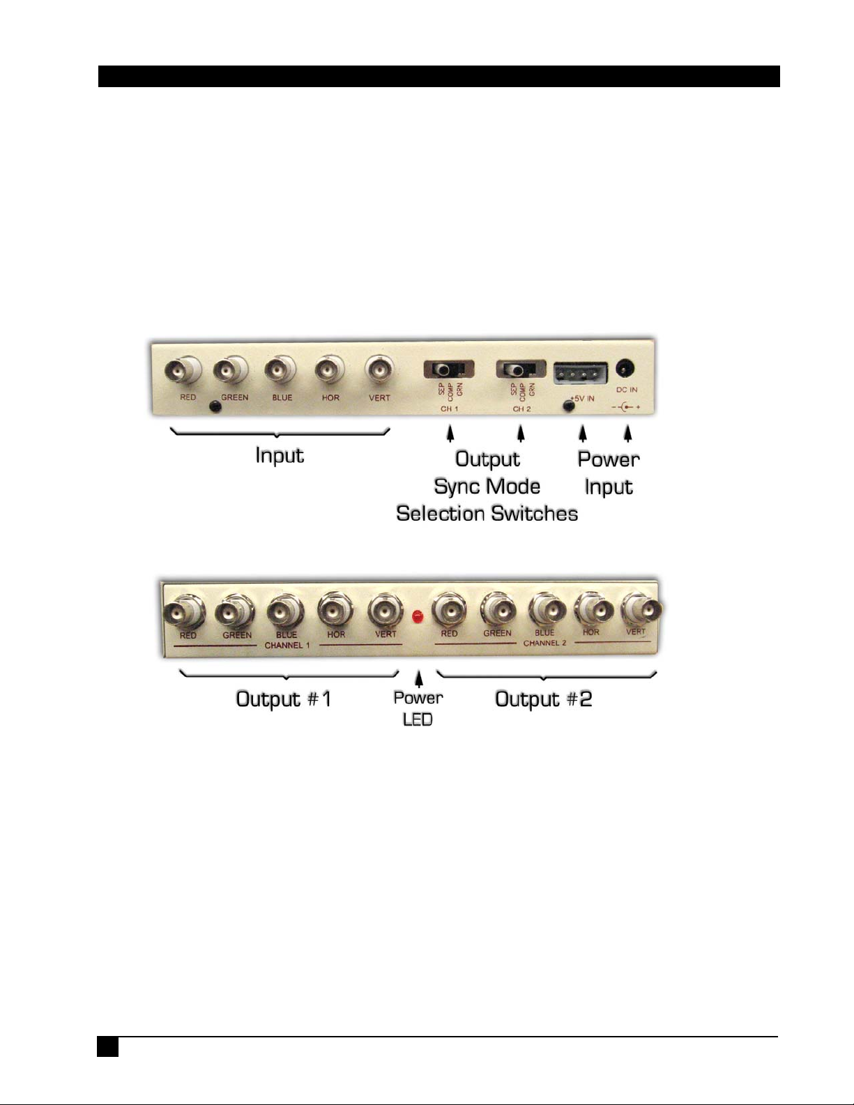
Connect the signal source to the input terminals and also connect the outputs. Place the selector switches for each
output according to the instructions in the next section.
Apply either the power from the provided AC adapter or 5vDC via the 4-pin Molex connector to turn on the device.
Operation
Regardless of the type of the input sync you can set the output sync mode.
When the switch is in "SEP", the output will have separate H and V syncs. In "COMP" mode the output will output
a composite-sync on the H output BNC. When in "GRN" a sync-on-green output is provided
The Model 210-LU automatically detects the input sync mode (by examining the signal at its V, H, and Green inputs
in that order, to determine what type of sync it is getting. Note that if you have RGBS (composite sync) on the input
then the Vertical input should have no connection or no signal.
The unit can create separate syncs form S, or strip the sync (sync-stripper) from the green input.
Usage Notes:
• The 210-LU does not change the resolution of the signal. So if your monitor does not support the resolution
of the input signal, you will not be able to get an image, regardless of what type of sync you output to it.
• HRT recommends that you put the output to "COMP” as default, since most monitors support that mode. If
you don’t get a picture, then try "SEP" or "GRN" in that order
• The 210-LU does not
• You can use the 210-LU to split YPbPr (component video), in that case set both switches to "GRN"
convert YPbPr (component video) to RGB or vice versa.
Power Requirements
The Model 210-LU can be powered from an external DC adapter (usually supplied) or, from a +5v DC source on a
Molex connector (same as those inside PC's used on hard disk drives).
Both connectors are present, giving you a choice of the way you supply power to the unit (but do not connect both
power supplies at the same time).
The external Power Adapter (wall mount) is 6 volt DC. Always use the adapters that came with the device, or
replace it with an identical unit.
The Molex connector is shown below. Note that you can use the PC power supply for this connection.
Pin 1 = No Connections in the unit
Pin 2 & 3 = Common (ground)
Pin 4 = +5v DC (regulated)
Page 4

3
210-LU
Specifications
Analog inputs: 3 BNC type labeled RED, GREEN, and BLUE
Input impedance: 75 ohm, voltage level: 3 vp-p max, 1 vp-p nominal
Sync inputs: 2 BNC type labeled HOR, VERT
Input impedance: 2 k ohm, voltage level: 0 - 5 v max, TTL
Analog outputs: 2 independent channels, 3 BNC's each
Output impedance: 75 ohm, short circuit protected, level: 1 vp-p nominal with termination
SYNC outputs: 2 TTL line driver BNC outputs per channel
Level: TTL compatible
Video amplifier: Greater than 300 Megahertz bandwidth, DC coupled
Composite sync: TTL on the HOR output, or sync-on-green depending on switch position
Comp sync polarity: Negative
Input power: 6vDC grounded adapter supplied (range 6 ~ 9 VDC). OR +5v DC grounded regulated power supply
on Molex connector.
Power consumption: 1.2 watts maximum
Physical: 8.88 x 3.13 x 1.35 inch (excluding connectors & mounting bracket) - weight: 1.2 lb
Federal Communications Commission Statement
This equipment can generate, use and radiate radio frequency energy and, if not installed and used in accordance with the
instructions, may cause harmful interference to radio communications. This equipment has been designed to comply with the
limits for a Class A computing device, pursuant to Part 15 of the FCC rules. Harmful interference when operated in a
commercial environment. Operation of this equipment in a residential area is likely to cause interference, in which case the
user, at their own expense, will be required to take whatever measures are necessary to correct the interference.
Warranty
HRT warrants that the supplied equipment is free from defective workmanship and material. Subject to the
agreements set forth, will repair or replace, at its option, the defective components for a period of 2 years after
purchase. The following conditions apply to the Warranty:
• Warranty void if item subject to improper use, negligence, or unauthorized modification
• Instructions must be followed in obtaining RMA number as explained below
• Any defective part should be returned, insured and freight prepaid, to Hall Research, with the following:
Return Material Authorization Number (RMA#)
Description of failure, as detailed as possible
Shipping address and contact name and phone number
© Copyright 2007. Hall Research Technologies, Inc.
All rights reserved.
1163 Warner Ave., Tustin, CA 92780
Ph: (714)641-6607, Fax: (714)641-6698
 Loading...