

Page 1
Hall Research Technologies, Inc
1163 Warner Ave.
Tustin, CA 92780
Phone: (714) 641-6607
Fax: (714) 641-6698
Usseerr’’ss
U
Maann
M
uaall
u
18-Channel
VGA Video Splitter / Distribution Amplifier
November 17, 2005
UMA1004 Rev. n/c
Page 2
Description
The Model 1800-RA is a VGA (RGBHV) video splitter that employs the latest technologies in high-resolution
video distribution. The rack-mountable unit provides one VGA input and 18 VGA outputs. 16 of the 18 outputs can
be boosted beyond the normal signal levels in order to drive long cable up to several hundred feet.
The device is rugged, rack-mountable, low power, and highly reliable. The can reproduce a sharp and crisp image at
any resolution up to 1600 x 1200.
The Splitter has a built-in universal power supply. And comes with a 6 ft multi-coaxial cable for connection to the
PC’s video.
Features
• Supports any resolution up to 1600x1200 at refresh rates from 60 to 85 Hz
• Rugged, Reliable, Economical
• No software required
• Drives cables to 300 ft or more
• Easily expand outputs by daisy-chaining
Setup
Your package should include a six foot VGA-Type video cable, a power cable, and the Video Splitter unit itself.
Please take inventory of all items received and ensure that you have the above items.
Locate the Video output connector on the Computer. This connector is generally a HD15 female with three rows of
contacts. Using the cable supplied, connect the input of the Splitter to the computer.
Connect the monitors directly to the outputs of the Splitter, or use high-quality extension cables to remotely locate
the monitors. Connect the AC power to the Splitter.
If you are using long video cables (greater than 25 feet) on the output of the splitter, it is best to ensure that the cable
is connected to a monitor (which properly terminates the signals), otherwise disconnect the cable from the Splitter.
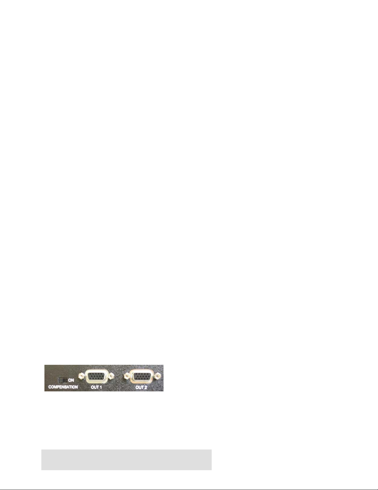
Driving Long Cables
The outputs numbered 1 to 16 can drive cables longer than 100 feet. These ouputs are devided in to 4 groups of 4
channels (i.e. group 1 is comprised of Out_1 through Out_4, group 2 is comprised of Out_5 through Out_8, etc.).
Each group of 4 has a switch that sets its output drive capability to normal or boosted. If the cable connected to the
output is less than 100 feet set the switch to the left, otherwise set it to the right for boosed output.
Outputs 17 and 18 are always normal and cannot be boosted, they are good for monitors that are located upto 100 or
150 feet from the unit.
Page 2 of 4
. . . . . . . . . . . . . . . . . . . . . . . . . . . .
Page 3

Connection Diagram
Specifications
Equipment included:
• North American AC power cord (European also available upon request)
• 6 ft, high-resolution (multi-coaxial) video input cable
• User’s Manual
Dimensions: 15.5 " wide x 3.19" high x 10" deep
Video Specs:
Connectors Input and Outputs: HDD15 female
Coupling DC
Signal Level Video: 0.7 v p-p
Bandwidth: Range: DC to 250 MHz Min. - 350 MHz Max.
Input impedance: Video: 75 ohms on RGB, 330 ohms on H,V
Input Power Requirement: 100 to 240 v AC, 50~60 Hz, 25 Watts
Page 3 of 4
. . . . . . . . . . . . . . . . . . . . . . . . . . . .
Page 4

Federal Communications Commission Statement
This equipment generates, uses and radiates radio frequency energy and, if not installed and used in accordance with the instructions,
may cause harmful interference to radio communications. This equipment has been tested and found to comply with the limits for a
Class A computing device, pursuant to Part 15 of the FCC rules. Harmful interference when operated in a commercial environment.
Operation of this equipment in a residential area is likely to cause interference, in which case the user, at his own expense, will be
required to take whatever measures are necessary to correct the interference.
If necessary, you should consult the place of purchase or and experienced radio/television technician for additional suggestions.
Warranty
HRT warrants that the supplied equipment is free from defective workmanship and material. Subject to the
agreements set forth, will repair or replace, at its option, the defective components for a period of 2 years after
purchase. The following conditions apply to the Warranty:
• Warranty void if item subject to improper use, negligence, or unauthorized modification
• Instructions must be followed in obtaining RMA number as explained below
• Any defective part should be returned, insured and freight prepaid, to Hall Research, with the following:
Return Material Authorization Number (RMA#)
Description of failure, as detailed as possible
Shipping address and contact name and phone number
Limited Liability
IN NO EVENT SHALL THE DIRECT VENDOR’S LIABLITY EXCEED THE PRICE PAID FOR THE PRODUCT FROM DIRECT, INDIRECT,
SPECIAL INCIDENTAL OR CONSEQUENTIAL DAMANGES RESULTING FROM THE USE OF THE PRODUCT OR ITS
DOCUMENTATION
© Copyright 2005. Hall Research Technologies, Inc.
All rights reserved.
Page 4 of 4
1163 Warner Ave., Tustin, CA 92780
Ph: (714)641-6607 , Fax: (714)641-6698
. . . . . . . . . . . . . . . . . . . . . . . . . . . .
 Loading...