


TT Basic-Engelska
USER GUIDE
ORIGINAL INSTRUCTIONS
BASIC
Hallins Sales AB
Box 24
SE-599 21 ÖDESHÖG
Tel.: +46 (0)144-15300
Fax: +46 (0)144-31400
Email: support@hallins.com Version: 1.0
Web: www.hallins.com or www.temptainer.se Date: 02/09/2016

2
1. CONTENTS
1. CONTENTS ....................................................................................................................... 2
3. INTRODUCTION ............................................................................................................... 3
4. DELIVERY AND ASSEMBLY ............................................................................................ 4
5. WARRANTY ...................................................................................................................... 5
6. USE ................................................................................................................................... 6
SAFETY ................................................................................................................................ 6
IMPORTANT – for trolleys with active heating and cooling ............... Fel! Bokmärket är inte
definierat.
BEFORE STARTING WORK ................................................................................................ 7
DURING WORK .................................................................................................................... 7
TEMPTAINER BASIC WITH CONVECTION HEATING ........................................................ 8
TEMPTAINER BASIC WITH COMPRESSOR ACTIVE COOLING TECHNOL OGY ............. 9
TEMPTAINER BASIC WITH COMBINED ACTIVE HEATING AND ACTIVE CO OLING ....... 9
TEMPTAINER BASIC IN NEUTRAL DESIGN ..................................................................... 10
TRANSPORT ...................................................................................................................... 10
7. MAINTENANCE AND TROUBLESHOOTING ................................................................. 11
CLEANING .......................................................................................................................... 11
MAINTENANCE .................................................................................................................. 11
TROUBLESHOOTING ........................................................................................................ 12
8. OVERVIEW AND TECHNICAL DATA ............................................................................. 13
OVERVIEW – general inform ati on ...................................................................................... 13
DIGITAL DISPLAY – CONTROL ......................................................................................... 14
SINGLE ............................................................................................................................. 155
TOWER ............................................................................................................................. 166
9. SPARE PARTS .............................................................................................................. 177
10. STICKERS .................................................................................................................... 18
12. OPERATION BOOK - SERVICE AND MAINTENANCE ............................................... 19
13. RECYCLING ............................................................................................................... 200
14. EU DECLARATION OF CONFORMITY ...................................................................... 211

3
2. INTRODUCTION
Use and layout are generally the same for all models; any significant differences are shown in
the text and pictures.
Please remember that: Only qualified personnel may use the trolley!
Before using the trolley for the first time, the operator is obliged to study and then observe the
instructions in this manual.
The correct use, operation, inspections and maintenanc e of this mac hi ne ar e cri ti cal for
executing your work effectively and safely and for the trolley's useful life.
This manual must be available to all relevant personnel, be kept in a protected place and
accompany the product if transferred to another location.
If you have any questions – contact your supplier.
The relevant part number and seri al nu mber may be found on the t r oll ey's machine plate.
The following symbol is used in this manual:
IMPORTANT!
- to emphasise important information or warn of potential risks, etc.

4
3. DELIVERY AND A SSEMBLY
When the trolley arrives at your location, it has been checked, tested and cleaned in the
factory.
As the recipient of this shipment, it is very important that you check the shipment immediately
on arrival!
The following points must be checked immediately upon receipt:
• Check that the shipment is intact! Check that there are no visible damage/defects on the
shipment. Shipment = Packaging and product.
• Check that the quantity is correct.
• Check that it is the correct product.
Any deviations from the above must ALWAYS and IMMEDIATELY be noted on the
consignment note before acknowledging receipt of the shipment to the carrier!
Also contact Hallins, ideally at once but no later than three days after receipt of the shipment.
Tel.: +46 144 15 300 (ask for Sales Support).
Email: claim@hallins.com
Temptainer Basic are normally delivered upright on a pallet, enclosed in protective plastic and
secured with plastic straps (although this may vary slightly, depending on the delivery
method).
IMPORTANT!
When removing the packaging, take care to ensure that the power cable is
not damaged.
After unpacking, hand the packaging materials in for proper recycling.
NOTE!
Always clean the trolley before use!

5
4. WARRANTY
The manufacturer will rectify any faults that can be attributed to production or material faults
and that occur within 24 months of delivery.
The warranty also applies in accordance with the following provisions:
BFS 2009 General provisions for the supply of catering equipment.
NL 09 General provisions for the supply of machinery and other mechanical,
electrical and electronic equipment.
ORGALIME 2012 General provisions for the supply of machinery and other mechanical,
electrical and electronic equipment.

6
5. USE
The Temptainer Basic is designed to be used for the transport of food in an indoor
environment under normal conditions in terms of temperature, humidity and lighting.
The surface should be level, hard and non-slip and have no cavities or obstructions.
The Temptainer Basic should normally be moved by hand, although some versions may also
be moved in a chain.
If necessary the Temptainer Basic can be transported betw een di ff erent indoor environments
using, for example, a truck or another covered vehicle.
In order to utilise the qualities of the trolley to the greatest effect and to prevent injury, it is vital
that you read through these instructions carefully and that you use the trolley in the correct
way.
SAFETY
The trolley has been designed and fitted with safety devices to prevent and avoid injury and
accidents.
The safety devices must not be put out of service or removed.
Modifications to the trolley that affect operational safety are not permitted.
It is extremely important that users are familiar with how the trolley works and the correct way
to use it.
The rules of the Swedish Occupational Safety Authority [Arbetsskyddsverket] must always be
observed, minimum requirements in accordance with Directive 2009/104/EC.
IMPORTANT
The food trolley may only be used for its intended purpose and by people who
are qualified to use it.
Never use the trolley if damage or faults have occurred that affect operational
safety. Never use the trolley if it has been repaired, modified or adjusted without
the approval of the person responsible. Faults in the trolley and deficiencies in
the working environment must be reported to a supervisor.
Remember that you as user are responsible for ensuring no one is injured.
The trolley must be used in such a way that injury to persons or damage to property does not
occur.
• Signs and markings must not be removed or made illegible.
• The trolley must undergo preventive maintenance on a regular basis for the purpose of
avoiding accidents. Re ad mor e abo ut maintenance in Chapter 7.
7
IMPORTANT
When using in public environments, particularly where children may be present,
the user must take adequate meas ur es to pre v ent people from entering the
work area.
We recommend that a risk analysis be prepared for the environment in
question.
BEFORE STARTING WORK
• Make sure that the trolley is used on a firm, smooth surface.
• Always use protective shoes, gloves and clothing as required.
DURING WORK
• Maintain full supervision of the trolley when it is moving. Look out for other mo bil e
machines and objects in the vicinity.
• Be aware of the risk of tipping! The trolley may only carry loads for which it is designed,
and these loads must be stable and securely arranged.
• Do not let the trolley come into contact with other objects.
• Be aware of the risk of trapping when working with trolleys on wheels.
• It is forbidden to travel on the trolley.
• When the trolley is parked or left unsupervised, the wheel brake must always be
locked.
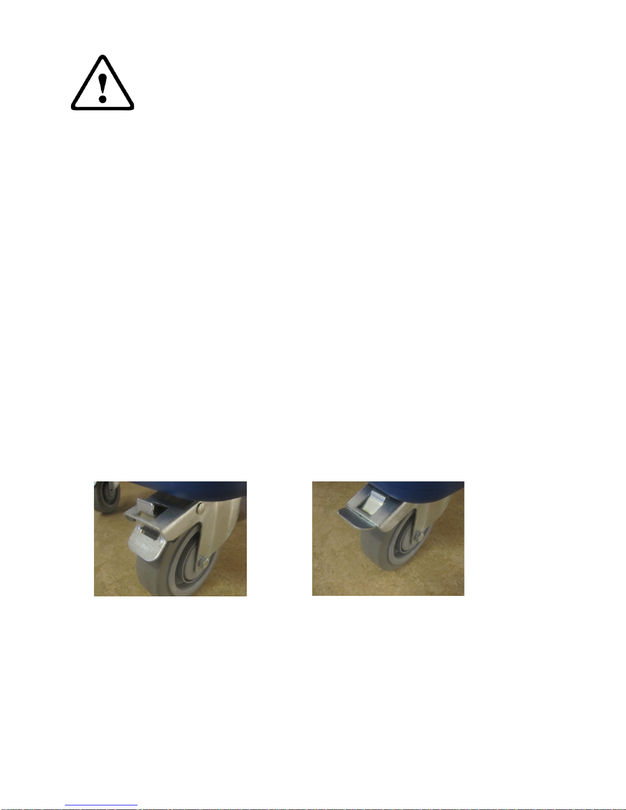
Wheel with a foot brake
The brake when locked. The brake when released.

8
TEMPTAINER BASIC WITH CONVECTION HEATING
* On/off knapp
1.
Connect the power cable to an earthed electrical socket (230-240 V~) and press *on at
the on/off-button to start the heating process.
NOTE!
The trolley should be switched on approx. 20 minutes be fore use so that the
temperature reaches the right heating temperature (approx. +85°C).
The trolley has a preset thermostat, which may only be changed by a qualified service
engineer.
2.
The temperature indicator on the door of the trolley shows the actual temperature
reached in the trolley.
3.
When the temperature in the trolley has reached the right level, vessels containing hot
food may be placed in the trolley.
4.
Only place well heated items in the hot cabinet.
Bear in mind!
Use containers with lids for the best temperature retention and avoid opening them and
the doors unnecessaril y.
The better the areas are filled, the better the ability to maintain the correct temperature.
5.
Conclude the heating up process by pressing off at the *on/off-button and detaching the
power cable from the electricity socket.

9
TEMPTAINER BASIC WITH COMPRESSOR COOLING TECHNOLOGY
* On/off knapp
1.
Connect the power cable to an earthed electrical socket (230-240 V~) and press *on at
the on/off-button to to start the cooling process.
The trolley should be switched on approx. 40 minutes before use so that the
temperature reaches the right cooling temperature (approx. +4°C).
The trolley has a preset thermostat, which may only be changed by a qualified service
engineer.
NOTE!
The rear side of the trolley must have clearance from the wall or other objects of at least
5 cm.
2.
The temperature indicator on the front shows when the trolley has reached the actual
temperature reached in the trolley.
3.
When the temperature in the trolley has come down to the right level, vessels
containing food may be placed in the trol l ey .
4. Only place well cooled items in the cold cabinet.
Bear in mind!
Use containers with lids for the best temperature retention and avoid opening them and
the doors unnecessaril y.
The better the areas are filled, the better the ability to maintain the correct temperature.
5.
Conclude the cooling process by pressing off at the *on/off-button and detaching the
power cable from the electricity socket.
TEMPTAINER BASIC WITH COMBINED ACTIVE HEATING AND ACTIVE COOLING
* On/off knapp
1.
Connect the power cable to an earthed electrical socket (230-240 V~) and press *on at
the on/off-button to start the cooling/heating process.
The trolley should be switched on approx. 40 minutes before use in order to come down

10
to the right cooling temperature (approx. +4°C) or heating temperature (approx. +85°C).
The trolley has a preset thermostat, which may only be changed by a qualified service
engineer.
NOTE!
The rear side of the trolley must have clearance from the wall or other objects of at least
5 cm.
2.
The temperature indicator on the front shows the actual temperature reached in the
trolley.
3.
When the temperature in the trolley has come up/down to the right level, vessels
containing hot or cold food may be placed in the relevant trolley.
4.
Only place well cooled items in the cold cabinet.
Bear in mind!
Use containers with lids for the best temperature retention and avoid opening them and
the doors unnecessaril y.
The better the areas are filled, the better the ability to maintain the correct temperature.
5.
Conclude the cooling/heating process by pressing off at the *on/off-button and
detaching the power cable from the electricity socket.
TEMPTAINER BASIC IN NEUTRAL DESIGN
The Temptainer Basic in neutral design has neither active cooling nor heating, but is used
primarily to transport food.
It is, however, easier to maintain the temperature of the food using the trolley.
In order to maintain the low temperature of cooled items, the trolley may be placed in a cold
room before use and fitted with cooling and freezing lamps.
TRANSPORT
The Temptainer Basic is designed to be used to transport food in an indoor environment.
The Temptainer Basic is normally transported or moved by hand, although some versions
may also be moved in a chain.
This kind of transport uses a pulling device consisting of a pin and tow-bar, which are
available as options from Hallins.
The maximum number of trolleys that may be connected in a chain is four.
If necessary, the Temptainer Basic can be transported or moved between different indoor
environments using, for example, a truck or another covered vehicle.
IMPORTANT
It is very important to secure the trolley in the vehicle using suitable equipment
to make sure that there is no risk of the trolley tipping over during vehicle
transport!
Whatever the means of the transport, the surface must be level, hard and nonslip and have no cavities or obstructions.

11
6. MAINTENANCE AND TROUBLESHOOTING
This chapter describes the maintenance required for the trolley to function in the best way
possible as well as troubleshooting for rectification by the user.
In addition to this manual, it is possible that we may send separate instructions that
accompany the trolley in terms of maintenance and troubleshooting.
NOTE!
Only Hallins original spare parts may be used when replacing parts. Failure to observe this
may nullify the warranty obligation in full.
CLEANING
IMPORTANT
Under no circumstances may the Temptainer Basic be connected to the mains
supply during cleaning. Always remove the mains cable from the electrical
socket before cleaning.
As the Temptainer Basic contains electrical components, it is very important that cleaning is
carried out with care.
The Temptainer Basic may be cleaned using standard detergents used in restaurants and
catering operations.
NOTE!
Corrosive detergents may not be used.
MAINTENANCE
In order for your Temptainer Basic to work in the best possible way, it is important to perform
regular maintenance in accordance with the following.
IMPORTANT
Check that the trolley is not connected to the mains when commencing
maintenance.
Frequency
Procedure
Each day
1. Clean the trolley in accordance with cleaning instructions.
2. Check that the trolley's electrical components and flex
holder are free from defect.
3. Check that signs and marks are intact and legible.
Every month
1. Check all electrical connections and components and
rectify any damage and wear. Replace with new parts
where necessary.

12 2. Check that all screws and nuts are properly tightened.
3. Check that all wheels rotate freely and that the tyre coating
is intact.
4. Check that the wheel brakes are undamaged and work
properly.
5. Check the fan in the trolley with Peltier cooling, clean as
required.
TROUBLESHOOTING
The trolley has been designed and tested to achieve optimal operational reliability and service
life, under the proviso that regular maintenance is carried out in accordance with the specified
instructions. If despite this a problem should occur, use the troubleshooting list below to
obtain relevant guidance.
If problems persist after you have taken the measures specified in the list below, you should
contact an authorised service engineer or Hallins Sales AB.
Symptom
Procedures
Trolley with active heating
does not heat up.
A. Check that the flex holder is conn ect e d to the mai ns .
B. Check that the unit is in on-mode (ON/OFF-button)
C. Check that the flex holder has not been da mag ed.
D. Check that the connections in the trolley and flex holder are
intact.
E. Contact a qualified service engineer.
Trolley with active cooling
does not cool down.
A. Check that the flex holder is conn ect e d to the mai ns .
B. Check that the unit is in on-mode (ON/OFF-button)
C. Check that the flex holder has not been damaged.
D. Check that the connections in the trolley and flex holder are
intact.
E. Check that the fans in trolleys with Peltier cooling are clean.
F. Contact a qualified service engineer.
7.
Model IP class, internal IP class, external Cleaning permitted
Neutral (N)
IP55
IP55
May be rinsed with water both
internally and external ly.
Active heating
(HS)
IP55
IP21
May be rinsed with water
internally, external cleaning with
damp cloth.
Active cooling
(CC)
IP55
IP21
May be rinsed with water
internally, external cleaning with
damp cloth.
Active heating +
Active cooling
(HS+CC)
IP55
IP21
May be rinsed with water
internally, external cleaning with
damp cloth.

13
8. OVERVIEW AND TECHNICAL DATA
OVERVIEW – general information
The Temptainer Basic from Hallins is available in several options. The size of the trolleys is
described using the number of guides, normally 12 guides, with guide gaps of 80 mm. The
trolleys are adapted to gastronorm standards and only gastronorm containers, trays, etc. may
be used.
There are three different models, Single and Tower,
each of which can have the following functions:
- neutral (N),
- active heating (HS),
- active cooling (CC),
- or a combination of these.
Cooling is based on compressor technology (CC).
The Neutral (N) trolley has no active heating or cooling function.

14
Digital controllers with off cycle defrost, AUX relay,
power supply 100 or 230VAC with or w/out battery
backup.
XR30CX
REF. 0-7020115, 0-7020110, 0-7020122, 0-7020202, 7020346.
1. GENERAL WARNING
1.1 PLEASE READ BEFORE USING THIS MANUAL
This manual is part of the product and should be kept near the instrument for easy and quick
reference.
The instrument shall not be used for purposes different from those described hereunder. It
cannot be used as a safety device.
Check the application limits before proceeding.
3. MAX & MIN TEMPERATURE MEMORIZATION
3.1 HOW TO SEE THE MIN TEMPERATURE
1. Press and release the DOWN button.
2. The “Lo” message will be displayed followed by the minimum temperature recorded.
3. By pressing the DOWN button again or by waiting for 5s the normal display will be restored.
3.2 HOW TO SEE THE MAX TEMPERATURE
1. Press and release the UP button.
2. The “Hi” message will be displayed, followed by the maximum recorded temperature.
3. By pressing the UP button again or by waiting for 5s, the normal display will be restored.
3.3 HOW TO RESET THE MAX AND MIN TEMPERATURE RECORDED
1. Keep SET button pressed more than 3s while the max or min temperature is displayed
(“rSt” message will be displayed).
2. To confirm the operation the “rSt” message starts blinking and the normal temperature will be
displayed.
2. FRONT PANEL COMMANDS
To display target set point.
In programming mode it selects a parameter or confirm an operation.
(DEF) To start a manual defrost.
(UP) To see the max stored temperature. In programming mode it browses
parameters or increases the displayed value.
(DOWN) To see the min stored temperature. In programming mode it
browses the parameters or decreases the displayed value.
To switch the instrument on and off when onF=oFF.
NOT USED
+ To lock & unlock the keyboard.
2.1 USE OF LEDS
Each LED function is described in the following table.
LED MODE FUNCTION
ON Compressor enabled
Flashing Anti-short cycle delay enabled
ON
Defrost enabled
ON
An alarm is occurring
ON
Continuous cycle is running
ON
Energy saving enabled
°C/°F
ON Measurement unit
Flashing Programming phase
4. MAIN FUNCTIONS
4.1 HOW TO SEE THE SETPOINT
1. Push and immediately release the SET button: the display will show the
Set point value;
2. Push and immediately release the SET button or wait for 5 seconds to
display the probe value again.
4.2 HOW TO CHANGE THE SETPOINT
1. Keep SET button pressed more than 2 seconds to change the Set point value.
2. The value of the set point will be displayed and the “°C” or “°F” LED icon will start blinking.
3. To change the Set-point value, push the UP or DONW buttons within 10s.
4. To memorise the new set point value, push the SET button again or wait for 10s.
4.3 HOW TO LOCK THE KEYBOARD
1. Keep pressed for more than 3 s the UP + DOWN buttons.
2. The “PoF” message will be displayed and the keyboard will be locked. At this point it will be
possible only to see the set point or the MAX o Min temperature stored
3. If a button is pressed more than 3s the “PoF” message will be displayed.
4.4 TO UNLOCK THE KEYBOARD
Keep pressed both UP and DOWN for more than 3s till the “Pon” message will be displayed.
4.5 THE ON/OFF FUNCTION
When “onF=oFF”, pushing the ON/OFF key, the instrument is switched off. The “OFF”
message is displayed. In this configuration, the regulation is disabled.
To switch the instrument on, push again the ON/OFF key.
WARNING: Loads connected to the normally closed contacts of the relays are always
supplied and under voltage, even if the instrument is in stand by mode.
5. PARAMETERS
REGULATION
LS Minimum set point: (-100°C÷SET; -148°F÷SET) it sets the minimum value for the
set point.
US Maximum set point: (SET÷150°C; SET÷302°F) it sets the maximum value for set
point.
temperature is given by the ALL or ALU values. rE = temperature alarms are referred
to the set point. Temperature alarm is enabled when the temperature exceeds the
[SET+ALU] or [SET-ALL] values.
ALU MAXIMUM temperature alarm:
ALC=Ab: (SET÷150°C; SET÷302°F)
ALC=rE: (0.1÷50°C; 1÷90°F)
When this temperature is reached, the alarm is enabled, possibly the ALd delay
time.
ALL Minimum temperature alarm:
ALC=Ab: (-100.0 ÷ SET°C; -148÷302°F)
ALC=rE: (0.1÷50°C; 1÷90°F)
When this temperature is reached, the alarm is enabled, possibly the ALd delay time.
AFH Differential for temperature alarm recovery: (0.1÷25.5°C; 1÷45°F) intervention
differential for recovery of temperature alarm.
ALd Temperature alarm delay: (0÷255 min) time interval between the d etection of an
alarm condition and alarm signalling.
dAo Exclusion of temperature alarm at start-up: (0.0÷23h 50min, res. 10min) time
interval between the detection of the temperature alarm condition after instrument
power on and alarm signalling.
ALARM RELAY MANAGEMENT –FOR BATTERY-BACKUP MODELS (7020122 and 7020202)
tbA Alarm relay silencing (with oA1=ALr): (n, Y)
n = silencing disabled; alarm relay stays on till alarm condition lasts.
Y = silencing enabled; alarm relay is switched OFF by pressing a key during an
alarm.
Aro Alarm relay activation with power failure: (n, Y)
n = the alarm relay is never activated during a power failure.
Y = the alarm relay is activated during a power failure.
ALF Alarm relay activation for all the alarms: (n, Y)
n = the alarm relay is activated only in case of a temperature alarm or regulation
probe failure.
Y = the alarm relay is activated for all the alarms.
bon Time of buzzer restart after muting, in case of alarm duration: (0÷30min) when
0 the buzzer is always off after muting.
AoP Alarm relay polarity: it set if the alarm relay is open or closed when an alarm
happens. CL= terminals 1-2 closed during an alarm; oP = terminals 1-2 open during
an alarm
DIGITAL INPUT
i1P Digital input polarity: (oP; CL) oP = the digital input is activated by opening the
contact; CL = the digital input is activated by closing the contact.
i1F Digital input configuration: (EAL; bAL; PAL; dor; dEF; AUS; Htr; FAn; ES)
EAL = external alarm: “EA” message is displayed; bAL = serious alarm “CA”
message is displayed. PAL = pressure switch alarm, “CA” message is displayed; dor
= door switch function; dEF = activation of a defrost cycle; AUS =to switch on the
second relay if oA1 = AUS; Htr = kind of action inversion (cooling – heating); FAn =
6. ALARM MESSAGES
6.1 OTHER MESSAGES
Pon Keyboard unlocked.
PoF Keyboard locked
7. TECHNICAL DATA
Housing: self extinguishing ABS.
Case: XR30CX frontal 32x74mm; depth 60mm.
Mounting: XR30CX panel mounting in a 71x29mm panel cut-out.
Protection: IP20. Frontal protection: XR30CX IP65.
Connections: Screw terminal block 2.5 mm2 wiring.
Model 7020346 and 7020345: fast-on tabs 6,3mm for loads and power supply; Disconnect able
screw terminal blocks for probe, digital input and
Power supply: according to the model: 100Vac 10%, 50/60Hz; or 230Vac 10%, 50/60Hz, or
120Vac 10%, 50/60Hz, or
Power absorption: 3VA max.
Display: 3 digits red LEDs, 14.2 mm high.
Digital input: free voltage contact.
Analogue Input: a PT1000 or PTC probe, set via parameter.
Relay outputs:
Compressor: 20(8)A, 250Vac.
Alarm: SPDT 8(3)A, 250Vac.
Connectors for external backup battery (only for battery-backup model).
Data storing: on the non-volatile memory (EEPROM).
Kind of action: 1B. Pollution degree: 2. Software class: A.
Rated impulsive voltage: 2500V. Overvoltage Category: II.
Operating temperature: 0÷60°C.
Storage temperature: -30÷85 °C.
Relative humidity: 2085% (no condensing).
Measuring and regulation range:
Pt1000 probe: -100÷100°C (-148÷212°F).
PTC probe: -55÷150°C (-67÷302°F).
Resolution: 0.1°C or 1°C or 1°F (selectable).
Accuracy (ambient temp. 25°C): ±0.7 °C ±1 digit.
Only for battery backup model:
Type of battery: 6Vdc, 1.2Ah.
Charging time: 94hours.

15
TECHNICAL DATA – specific information
SINGLE
The Single model is a trolley in either compressor cooling (CC), convection heating (HS) or
neutral (N) version.
Figure 1. Single model with active compressor cooling (CC).
Front Back
Technical data – Single N
M6060012-01
Guide pair (qty)
12
Width x depth (mm) 500x770
Height (mm) 1380
Weight (kg)
50
Capacity (litres) Max 120
Wheel diameter (mm)
160 mm, 2 fixed,
2 swivel brake
Figure 1. Main parts of Temptainer Basic in Single design
1 Handle/bumper
4
Bumper
2
Temperature indicator
5
Wheel with foot brake
3
Handle/door lock
6
Power cable (not in neutral
trolley)
2 3 1 4 5 1 4
6
The item on the picture is equip with an extra
handle on the back

16
Technical data – Single HS
M6062012-01
Guide pair (qty) 12
Width x depth (mm)
500x770
Height (mm) 1380
Weight (kg)
55
Capacity (litres)
Max 120
Output (W) 230-240 V, 50-60 Hz, 1-
phase
800
Wheel diameter (mm) 160 mm, 2 fixed,
2 swivel brake
Technical data – Single CC
M6064012-01
Guide pair (qty)
12
Width x depth (mm) 500x835
Height (mm)
1380
Weight (kg) 65
Capacity (litres)
Max 120
Output (W) 230-240 V, 50-60 Hz, 1-
phase
136
Wheel diameter (mm) 160 mm, 2 fixed,
2 swivel brake
TOWER
The Tower trolley has double compartments, stacked. The compartment can be combined in
any way for cold, hot or neutral storage. .
Figure 2. Tower model with active heating and active cooling.
Front Back
3 2 1 4 5 1 4 3
6

17
Technical data – Tower CC+HS
M6071066-01
Guide pair (qty) 6+6
Width x depth (mm)
580x880
Height (mm) 1474
Weight (kg) 65
Capacity (litres)
Max 60+60
Output (W) 230-240 V, 50-60 Hz, 1-phase 136+800
Wheel diameter (mm)
160 mm, 2 fixed,
2 swivel brake
9. SPARE PARTS
If any component is no longer working, contact your supplier or Hallins.
Only Hallins original spare parts may be used when replacing parts. Failure to observe this
may nullify the warranty obligation in full.
Hallins stocks a full range of spare parts.
Returning spare parts
Do not return spare parts that have been worn through normal usage or damaged in an
accident.
Return worn, damaged or unusable parts if the defect is considered to fall under the warranty
obligation. If this is the case, return the parts immediately, as you may otherwise forfeit your
right to a replacement.
When ordering spare parts, please quote the trolley's Part number * and Serial number ** as
stated on the machine plate.
Figure 2. Main parts of Temptainer Basic in Tower design
1
Handle/bumper
5
Wheel with foot brake
2
Temperature indicator
6
Bracket for cable and pow er
cable (not in neutral trolley)
3
Handle/door lock
4
Bumper

18
10. STICKERS
Machine sign (individual)

19
11. OPERATION BOOK - SERVICE AND MAINTENANCE
PART NUMBER: ___________________________________________
SERIAL NUMBER:
___________________________________________
DELIVERED:
___________________________________________
SERVICE INTERVAL:
___________________________________________
SERVICE & MAINTENANCE
DATE ………………………………..
SIGNED …………………………………
OBSERVATIONS:………………………
…………………………………………
…………………………………………
SERVICE & MAINTENANCE
DATE ………………………………..
SIGNED …………………………………
OBSERVATIONS:………………………
…………………………………………
…………………………………………
SERVICE & MAINTENANCE
DATE ………………………………..
SIGNED …………………………………
OBSERVATIONS:………………………
…………………………………………
…………………………………………
SERVICE & MAINTENANCE
DATE ………………………………..
SIGNED …………………………………
OBSERVATIONS:……………………….
…………………………………………
…………………………………………
SERVICE & MAINTENANCE
DATE ………………………………..
SIGNED …………………………………
OBSERVATIONS:………………………
…………………………………………
…………………………………………
SERVICE & MAINTENANCE
DATE ………………………………..
SIGNED …………………………………
OBSERVATIONS:……………………….
…………………………………………
…………………………………………
SERVICE & MAINTENANCE
DATE ………………………………..
SIGNED …………………………………
OBSERVATIONS:………………………
…………………………………………
…………………………………………
SERVICE & MAINTENANCE
DATE ………………………………..
SIGNED …………………………………
OBSERVATIONS:………………………
…………………………………………
…………………………………………
SERVICE & MAINTENANCE
DATE ………………………………..
SIGNED …………………………………
OBSERVATIONS:………………………
…………………………………………
…………………………………………
SERVICE & MAINTENANCE
DATE ………………………………..
SIGNED …………………………………
OBSERVATIONS:……………………….
…………………………………………
…………………………………………
SERVICE & MAINTENANCE
DATE ………………………………..
SIGNED …………………………………
OBSERVATIONS:………………………
…………………………………………
…………………………………………
SERVICE & MAINTENANCE
DATE ………………………………..
SIGNED …………………………………
OBSERVATIONS:……………………….
…………………………………………
…………………………………………
SERVICE & MAINTENANCE
DATE ………………………………..
SIGNED …………………………………
OBSERVATIONS:………………………
…………………………………………
…………………………………………
SERVICE & MAINTENANCE
DATE ………………………………..
SIGNED …………………………………
OBSERVATIONS:………………………
…………………………………………
…………………………………………
SERVICE & MAINTENANCE
DATE ………………………………..
SIGNED …………………………………
OBSERVATIONS:………………………
…………………………………………
…………………………………………
SERVICE & MAINTENANCE
DATE ………………………………..
SIGNED …………………………………
OBSERVATIONS:……………………….
…………………………………………
…………………………………………
SERVICE & MAINTENANCE
DATE ………………………………..
SIGNED …………………………………
OBSERVATIONS:………………………
…………………………………………
…………………………………………
SERVICE & MAINTENANCE
DATE ………………………………..
SIGNED …………………………………
OBSERVATIONS:……………………….
…………………………………………
…………………………………………
SERVICE & MAINTENANCE
DATE ………………………………..
SIGNED …………………………………
OBSERVATIONS:……………………….
…………………………………………
…………………………………………
SERVICE & MAINTENANCE
DATE ………………………………..
SIGNED …………………………………
OBSERVATIONS:………………………
…………………………………………
…………………………………………
SERVICE & MAINTENANCE
DATE ………………………………..
SIGNED …………………………………
OBSERVATIONS:……………………….
…………………………………………
…………………………………………

20
12. RECYCLING
The Temptainer Basic is manufactured from recyclable materials, or from
materials that can be reused.
Specialist companies take care of worn-out trolleys, dismantle them and utilise
any materials that can be reused.
Electrical items must be t aken to speci al col l ect ion poi nts for electrical
materials.
Hallins Sales AB can offer a service to take care of worn-out Temptainer
Basic. Contact Hallins Sales AB for further information.

21
13. EU DECL ARATION OF CONFORMITY
Declaration of conformity in accordance with the Low Voltage Directive,
2006/95/EC,
the EMC Directive, 2004/108/EC and the Machine Directive, 2006/42/EC.
Manufacturer: Hallins Sales A B
Box 24
SE-599 21 ÖDESHÖG
Sweden
Tel.: +46 (0)144 – 153 00
Fax: +46 (0)144 – 314 00
Email: support@hallins.com
Web: www.hallins.com or www.temptainer.se
Representative: Company ___________________________
Address ___________________________
Tel. ___________________________
Fax ___________________________
Email ___________________________
declares that this Temptainer Basic has been manufactured in accordance with Directive
2006/42/EC of the European Parliament and of the Council of 17 May 2006 on the
approximation of the laws of the Member States relating to machinery, as well as the Low
Voltage Directive 2006/95/EC and the EMC Directive 2004/108/EC.
Serial No. ________________________________________
Product no.
Single: M6060012-01 – M6062012-01 – M6064012-01
Tower: M6071066-01
The relevant parts of the following harmonised standards have been observed in design and
manufacture:
EN 60335-1 Household and simil ar el ect ri c al appl i ances - Safety - General
requirements
EN 60335-2-49 Household and similar electrical appliances - Safety - Particular
requirements for commercial electric appliances for keeping food and
crockery warm
EN 60335-2-89 Household and simil ar el ect ri c al appl i ances - Safety - Part 2-89:
Particular requirements for commercial refrigerating appliances with
an incorporated or remote refrigerant condensing unit or compressor
EN 60204-1 Safety of machinery - Electrical equipment of machines - General
requirements.
EN 1672-2:2005 Food processing machiner y - Basic concepts - Part 2: Hygiene
requirements
ÖDESHÖG 02/09/2016 Tommy Hallin, CEO
 Loading...