

Hallikainen and Friends TEL171 Service manual

INSTALLATION, OPERATION, AND MAINTENANCE
TEL171
DIGITAL TELEMETRY CONVERSION KIT
Kallikainen and Friends, Inc.
101 Suburban Road
San Luis Obispo, California
(805) 541-0200
SPECIFICATIONS
TABLE OF CONTENTS
Page
WARRANTY. ...........................
INTRODUCTION. .........................
INSTALLATION. .........................
OPERATION ........................... 10
INSTALLATIONIDEAS ....................... 11
THEORY OF OPERATION.
Telemetry Transmitter 122lTT ............... 13
Telemetry Receiver 122lTR. ................
Telemetry Display 1231TD .................
Local Display 1281LD ...................
CIRCUIT ADJUSTMENTS ......................
1211TT telemetry Transmitter ............... 28
.....................
1
2
5
13
20
23
25
28
1221TR telemetry Receiver. ................ 28
PARTSLIST .......................... 30
12llTT .......................... 30
1221TR .......................... 33
1231TD .......................... 36
128lLD .......................... 37
TABLE OF CONTENTS (Cont'd)
ASSOCIATED DRAWINGS
Telemetry Transmitter Schematic
Telemetry Transmitter Component Placement
Telemetry Receiver Schematic
Telemetry Receiver Component Placement
Telemetry Display Schematic
Telemetry Display Component Placement
Transmitter Unit Installation
Studio Unit Installation
Telemetry Local Display Schematic
Telemetry Local Display Parts Placement
c-014
A-061
c-029
c-031
c-013
B-054
C-032
c-033
c-039
B-058
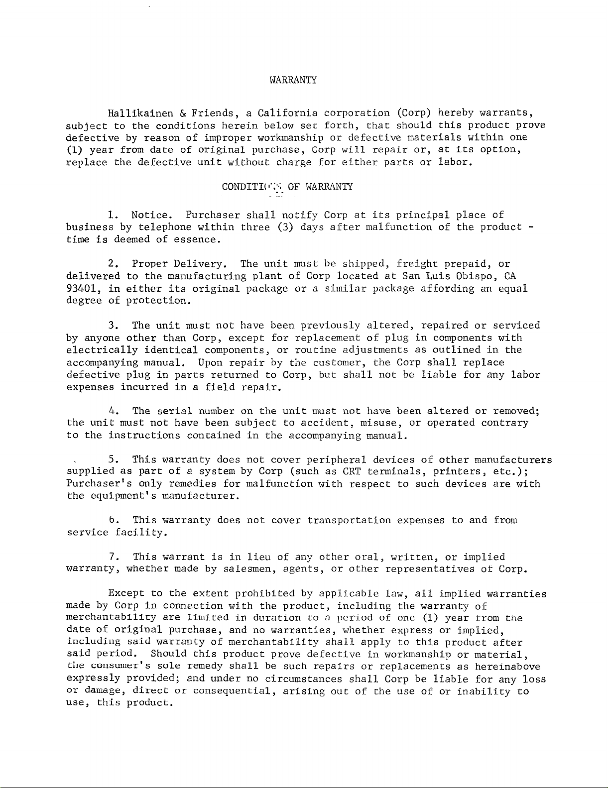
WARRANTY
Hallikainen & Friends,
subject to the conditions herein below set forth,
a California corporation (Corp) hereby warrants,
that should this product prove
defective by reason of improper workmanship or defective materials within one
(1) year from date of original purchase, Corp will repair or, at its option,
replace the defective unit without charge for either parts or labor.
CONDITI(l':>- OF WARRANTY
_ __.
1. Notice. Purchaser shall notify Corp at its principal place of
business by telephone within three (3) days after malfunction of the product -
time is deemed of essence.
Proper Delivery. The unit must be shipped, freight prepaid, or
2.
delivered to the manufacturing plant of Corp located at San Luis Obispo, CA
93401, in either its original package or a similar package affording an equal
degree of protection.
The unit must not have been previously altered, repaired or serviced
3.
by anyone other than Corp,
except for replacement of plug in components with
electrically identical components, or routine adjustments as outlined in the
accompanying manual.
defective plug in parts returned to Corp,
Upon repair by the customer, the Corp shall replace
but shall not be liable for any labor
expenses incurred in a field repair.
The serial number on the unit must not have been altered or removed;
4.
the unit must not have been subject to accident, misuse, or operated contrary
to the instructions contained in the accompanying manual.
5. This warranty does not cover peripheral devices of other manufacturers
supplied as part of a system by Corp (such as CRT terminals, printers, etc.);
Purchaser's only remedies for malfunction with respect to such devices are with
the equipment's manufacturer.
This warranty does not cover transportation expenses to and from
6.
service facility.
This warrant is in lieu of any other oral, written, or implied
7.
warranty, whether made by salesmen, agents, or other representatives of Corp.
Except to the extent prohibited by applicable law, all implied warranties
made by Corp in connection with the product, including the warranty of
merchantability are limited in duration to a period of one (1) year from the
date of original purchase, and no warranties,
whether express or implied,
including said warranty of merchantability shall apply to this product after
said period. Should
this
product prove deEective in workmanship or material,
the consumer's sole remedy shall be such repairs or replacements as hereinabove
expressly provided;
or damage, direct or consequential,
and under no circumstances shall Corp be liable for any loss
arising out of the use of or inability to
use, this product.
Digital Telemetry
, a--==-
/
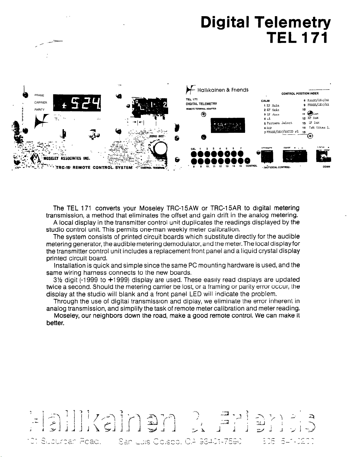
The TEL 171 converts your Moseley TRC-I 5AW or TRC-15AR to digital metering
transmission, a method that eliminates the offset and gain drift in the analog metering.
A local display in the transmitter control unit duplicates the readings displayed by the
studio control unit. This permits one-man weekly meter calibration.
The system consists of printed circuit boards which substitute directly for the audible
metering generator, the audible metering demodulator, and
the transmitter control unit includes a replacement front panel and a liquid crystal display
printed circuit board.
installation is quick and simple since the same PC mounting hardware is used, and the
same wiring harness connects to the new boards.
3% digit (-1999 to i-1 999) display are used. These easrly read displays are updated
twice a second. Should the metering carrier be lost, or a framing or parity error occur, the
display at the studio will blank and a front panel LED
Through the use of digital transmisston and diplay, we eliminate the error inherent in
analog transmission, and simplify the task of remote meter calibration and meter reading.
Moseley, our neighbors down the road, make a good remote control. We can make it
better.
the
meter.The local display for
will
indicate the problem.
TEL 171
TEL 171 Specifications
H&F 1211 TT Telemetry Transmitter
Substitutes for Moseley 51 A541 6 Audible Metering Generator.
A/D Conversion
Resolution: 3% digits (-1999 to +I 999)
Conversion Rate: 2 conversions/second
Accuracy: Limited by temperature stability of reference (LM399H).05O/6 of readrng fl
count, 0 degrees C to 50 degrees C
Full Scale Sensitivity: 2 Volts for +1999 indication.
Data Transmission
Bit Rate: 300 Baud
Character Rate: 4 characters per conversion
Word Rate: One word per conversion (2/s), each conversion transmitted once with
idle time between conversions.
Character Format: Start bit, six data bits, even parity bit, two stop bits. First four data
bits carry digit code in BCD (except for on half digit where three bits carry&, 0 or
1, and out of range indications). Last two data bits identify digit (00 half digit, 11
is last digit).
Word Format: Digits transmitted in order (0,1,2,3).
Data channel idle between conversions.
Encoding: FSK, 1270 Hz Mark, 1070 Hz Space.
Output Level: +l dBm into 600 ohms, adjustable (line), and 5 V P-P open circuit, Z=
2.2 K (subcarrier).
Display
3% digit LCD local display.
Power Requirements
Floating +15: 35 mA
Floating -15: 30 mA
+ 5: 0.2 mA
+I 5: 30 mA
H&F 1221 TR Telemetry Receiver
Substitutes for Moseley 51 A5420 Audible Metering Demodulator.
Minimum Receive Level: -40 dBm (7.7 mv)
Data Output: Character parallel, negative 250 US strobe, carrier, parity, and framing
alarms. All lTL levels.
Power Requirements: 5V, 100 mA
H&F 1231 TD Telemetry Display
Substitutes for Moseley meter.
3% drgrt LED display with PROM programmed decimal points.
All metering and control data presented on front panel connector for logging for ATS.
Power Requirements: +5V, 400 mA
2
INTRODUCTION
The TEL171 updates the Moseley TRC-15AW or TRC-15AR remote control
from analog metering to digital metering. The use of digital transmission
and display eliminates the calibration drift and reading problems associated
with analog transmission.
The system utilizes audible metering, as is standard in the
TRC-15AW.
The TRC-15AR normally uses subaudible metering.
rates involved,
practical.
The audible metering of the TEL171 can be used with wire lines
(TRC-15AW), or FM SCA (TRC-15AR) if no programming is run on the SCA.
On FM stations using the SCA for programming and AM stations using
a subaudible metering return, the use of wire lines or a remote telemetry
link (available from Moseley) is recommended.
The TEL171 consists of a set of four printed circuit boards that
substitutes directly for the audible metering generator, audible metering
demodulator, front panel meter, and transmitter unit front panel.
Connections to the transmitter and receiver boards utilize the existing
wiring harness,
subaudible transmission of digital metering is not
simplifying installation.
The remote meter is replaced
Due to the data
by an LED display board, which connects to the receiver board and the
Moseley channel select and raise/lower switches. The local display, which
can be deleted by specifying option 1 when ordering, substitutes for the
"slide-out" front panel on the transmitter unit. The local display
provides an LCD indication of the metering data at the transmitter site.
The local display plugs in to the telemetery transmitter board with a ribbon
cable.
3
The system converts the metering sample at the transmitter site to
a digital code. This code is displayed on the local display.
serialized (transmitted one data bit at a time), and optically coupled to
the remainder of the circuitry. The optical coupling, along with the
floating power supply provided by Moseley, allows metering of samples
that have both leads above or below ground potential.
The optical coupler drives a frequency shift keyed oscillator. This
converts the serial digital data to audio for transmission over wire
line, SCA, or radio telemetry link.
At the studio,
This filter passes only the desired metering signal while rejecting the
control signal that is present on two wire communications links, such
as wire lines.
the FSK metering signal is fed to an active filter.
It is also
The filtered metering data feeds a demodulator. This phase lock
loop demodulator converts the signal back to serial digital and provides
an indication of metering carrier presence. The carrier presence
indication drives the existing "read" lamp on the front panel of the
Moseley, and provides display blanking in the absence of carrier, since
any data obtained without carrier presence is not valid.
The demodulated data is converted back to bit parallel, buffered,
and sent to the display board.
The display board latches and displays the data.
blanked by the presence of a parity error, framing error, or absence of
carrier.
The display board also uses the Moseley channel select lines to
drive a programmable read only memory (PROM) to properly place the
The display is

decimal point for each metering channel.
All metering data and control lines are presented on a front panel
connector for dritiing a logger or ATS.
4
5
I :: rlALLATION
Installation is straightforward, since existing remote control
wiring is used.
It is suggested that the studio unit be taken to the transmitter
site during the installation to allow test of the system.
During installation, power should be removed from each unit.
If necessary, the transmitter can be kept on the air under local control.
On the transmitter unit,
control demodulator board after removing the two front hold-down screws.
The left-most board (as viewed from front) on the lower level
is the metering generator. Refer to installation drawing.
cut each wire of the harness connecting to the metering generator board
as close to the turret pin on the board as possible.
Remove the four mounting screws and the board.
Strip the insulation from the end of each cut harness wire.
Crimp one of the supplied disconnect pin receptables to each wire using
AMP tool # 29004-1, if available. Otherwise, solder each wire to a
receptacle.
Install the H&F 1211TT board, carefully noting proper orientation
in the installation drawing. Mount the board using the four screws
slide out the electronics. Lift the
Carefully
previously removed.
The local display may be deleted by specifying option 1 when
ordering the TEL171 system. If this option was specified, the following
information on the local display installation should be skipped.
The existing slide out panel on the transmitter site unit is to be
removed. The first step in this process is to carefully pry the mounting
rings on the back of the LED clips away from the panel.
should be slid back over the LED leads. Carefully push each LED out of
its mounting clip by pressing on the front of the LED with a small
screwdriver. Each LED should snap out of its mounting clip.
With an allen driver, remove the screws holding in the switch
assembly and those holding the front panel on the unit.
Carefully remove the front panel. Do not loose any of the LED
These rings
mounting rings,
Remove the H&F 1281 Local Display board from the new front panel
by releasing the locks on the plastic PC mounts.
Remove the LED mounting clips from the old front panel by
squeezing in the tabs of each clip on the rear of the panel and pushing
the clip out. Each of these clips should be snapped in to the new panel.
Remove the RF gasket finger stock from the old panel, and stick it
to the new panel in corresponding locations.
Put the new panel in position with one or two screws. Press each
LED in to the appropriate clip.
been moved to clear the local display PC. After each LED is snapped in
to position,
Mount the H&F 1281 PC board back in position. Mount the switches
which are now free to fall off the LEDs.
Note that the control presence LED has
slide the locking ring back on to the clips.
to the new front panel. Put the rest of the front panel mounting screws
in position.
Plug the DIP ribbon connector in between the local display board
and the telemetry transmitter board, carefully noting that pin 1 is
positioned properly.
Screw down the control demodulator board using the screws supplied,
and placing the plastic spacers under the board.
These spacers are
very important,
display board without them.
Inspect the installation to make sure there are no short circuits
between adjacent boards.
Remove the panel latches from the old panel. These can be removed
as the control demodulator board will not clear the local
by loosening the hex nut on the back of the latch slightly.
ring on the front of the panel can then be removed by hand. Place these
latches on the new panel.
Close the transmitter unit cabinet.
Open the studio unit cabinet. Remove the meter from the front
panel.
other circuitry.
drawing. Cut each harness wire connected to the metering demodulator
board as close to the turret pin as possible. Remove the metering
receiver board.
Tape the lugs on the end of the meter leads so they do not short
Identify the metering demodulator board on the studio installation
Install disconnect pin receptacles on each wire.
Carefully note the proper orientation of the H&E' 1221TR board on
The threaded
the studio unit installation drawing. Install the 1221TR board.
each harness connection on the appropriate pin on the board.
Install display panel and PC in the meter hole, from the back of
the panel. Secure the display panel with supplied screws, nuts, and
lockwashers.
Carefully note proper orientation of 7 pin connector, and plug it
on to the back of the display board. Connect the wires from this connector
to the channel select and raise/lower switches, as shown in drawing.
Plug
8
Plug the ribbon cable into the telemetry receiver board, and the
display board. Carefully note that each connector is installed properly.
The end of the plug that has the cable stripe on it has pin # 1.
On the telemetry receiver board, set the DIP switch for proper
operation.
For wire line,
turn switch 1 off, and switch 2 on.
For radio link, turn switch 1 on, and switch 2 off.
Switches 3 and 4 are for tune up. Switch 3 should be off and
switch 4 should be on for normal operation.
Temporarily turn on switch two to test the system.
pair of wires between the telephone line terminals on each unit.
Connect a
APPLY
power and verify that the system is operating properly.
Initial meter calibration can be completed at this time.
Set the
transmitter unit to local control and step through each of the metering
channels. Adjust the corresponding calibration pot for the proper indicat
on the studio unit. Note that the decimal point location is determined
by the channel select switch on the stuido unit, so it may not be in the
ion
proper location at this time.
In this test, only the metering link will work in a radio link
system, since the control signal is not being put on the wire line.
In a wire system, the whole system should work at this point.
Once the test is complete, set the DIP switch as outlined above.
Set the local/remote switch to remote.
Return the studio unit to the
stuido and install.
Once again, verify proper operation.

If a local display has been installed, it is desirable to label the
new control index. A piece of "copy zip" has been supplied for this
purpose. By lightly marking the proper position for each line of infor-
9
mation on the copy zip,
the new legend is typed on the copy zip, the backing is peeled off, and
the copy zip is stuck to the panel over the control index markings.
a neat label can be made on a typewriter. Once
OPERATION
Operation is simple!
Since metering transmission is digital, the zero and calibrate
controls no longer require adjustment, The offset and gain errors are
corrected for during each conversion cycle of the A/D converter.
All that is required for routine operation is to select the
required metering channel, wait for the reading to stabilize, and
read it.
If an ATS controller or transmitter logger is plugged into the
data jack, the channel selector must be left in calibrate to give full
control to the ATS or logger.
Calibration of each metering channel is accomplished the same
as previously. The local meters are read and the calibration pots
adjusted for the same readings at the studios.
If local display has been installed, remote meter calibration
can be achieved entirely at the transmitter site, since the studio
indication will duplicate the local display indication.
appropriate calibration pot for the proper indication on the local
display.
Adjust the
 Loading...