

Hallicrafters SX-62A, SX-62AU Operating And Service Instructions

GENERAL
SPECIFICATIONS
Tubes
...............
Fourteen
plus
v 0
It
age
regulator
and
rectifier
FREQUENCY COVERAGE
Speaker
Output
..........
3.2/8/500
Headset
Output
..........
High
impedance
Antenna Input. . . . . . . . . . .
For
50
to
600 ohm
line
or
single
wire
lead
-in
Phono
Input.
. . . . . . . .
.•.
High
impedance
External
Power
Connector
..
Std.
octal
socket
Tuning Range
..........
See
Frequency
Coverage
Intermediate
Frequency
Bands
1, 2, 3, 4 . . . .
...
455
KC
Bands
5, 6
...........
10.7
MC
Power
Supply
...
SX-62A 105-125V
50/60
Cycles
AC
SX-62AU 105-250V
25/100
Cycles
AC
Power
Consumption
......
120
Watts
BAND
1
2
3
4
5
6
FREQUENCY
TYPE
OF
RANGE
RECEPTION
540
KC
- 1620
KC
AM/CW
1.62
MC
-
4.9
MC
AM/CW
4.9
MC
-
15
MC
AM/CW
15
MC
-
32
MC
AM/CW
27
MC
-
56
MC
AM/FM/CW
54
MC
-
109
MC
AM/FM/CW
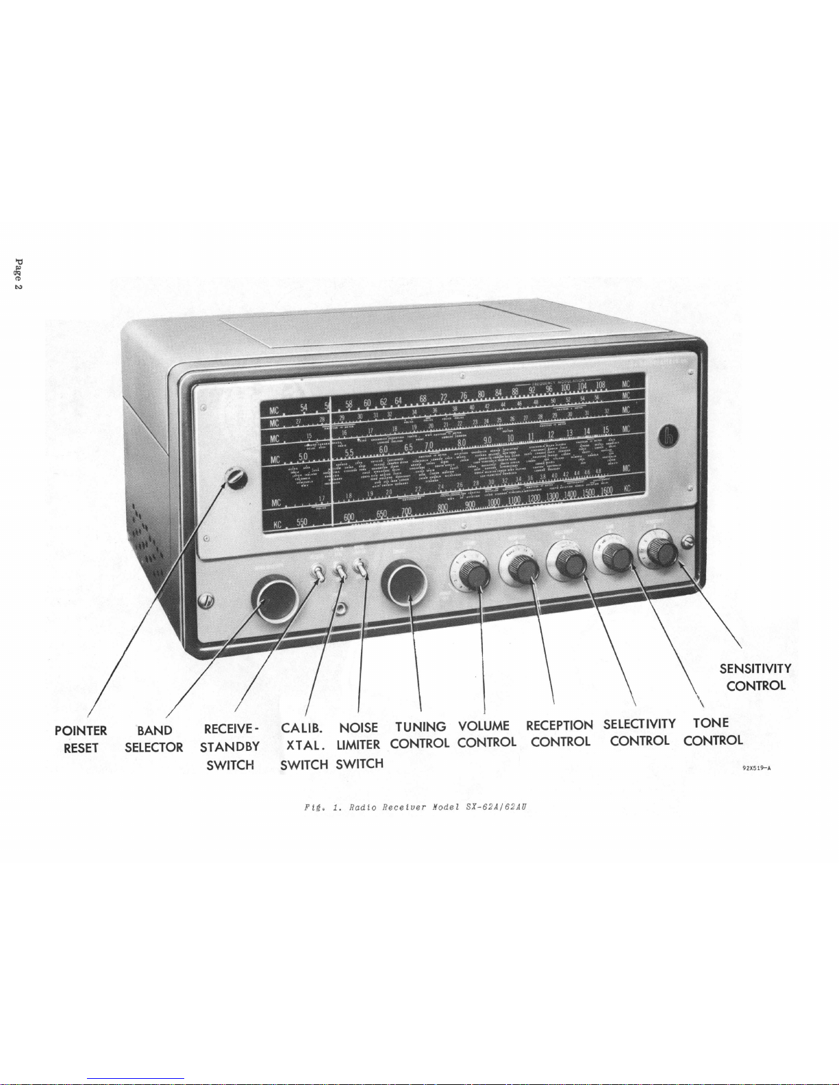
The Model SX-62A/62AU
is a sensitive
high fidelity
superheterodyne
receiver
covering
all
of the
broadcast-
ing
services
between 540
kilocycles
(KC) and 109
megacycles
(MC). The
receiver
is
capable
of
receiving
both the
FM
(Frequency
Modulation) and
AM
(Amplitude Modulation)
broadcasts
transmitted
in
this
frequency
range
as
shown
in
the
FREQUENCY COVERAGE
chart.
A
built-in
500 kc
crystal
controlled
calibrating
oscillator
and
adjustable
dial
pointer
permit
accurate
dial
calibra-
tion
on
the
large
direct
reading
slide
rule
dial.
Marker
signals
appear
every
500 kc on the dial
scale
with
this
type
of
marker
oscillator;
hence,
dial
calibration
may
be
held to
very
close
limits
over
the
entire
dial
scale
by
comparison
with the
marker
signal.
This
calibration
feature
of
the
receiver
makes
it
possible
to
log
the
most
prominent
shortwave
stations
by
countries
directly
on the
dial.
In addition, many of
the
active
communication
channels;
government,
amateur,
police,
aviation,
etc.
are
logged by
bars
to
indicate
their
location
on
the
dial.
World-wide
reception
is
accomplished
simply
by
selecting
the
desired
frequency
band (band
selector
switch) and
adjusting
the
tuning
control
so
that
the
pOinter
is
above
the
station
locating
dot.
The
receiver
selectivity
is
adjustable
to
accommodate
the
broad
response
required
for
high
fidelity
FM and
AM
broadcast
reception
to
the
sharpest
crystal
selectivity
required
for
code
reception
in the
crowded
channels
of the
short
wave
bands.
The
high fidelity tone
compensated
audio
system
provides
four
distinct
tone
ranges
covering
full
range
reception
for
entertainment
purposes
as
well
as
the
restricted
range
required
for
communication
work
in
either
voice
or
code.
An
automatic
noise
limiter,
operated
by a toggle switch,
permits
the
operator
to
reduce
the
background
noise
caused
by
severe
electrical
distrubances.
Background
noise
is
reduced
in
the
receiver
with a
minimum
of
audio
distortion.
A RECEIVE-STANDBY
switch
permits
receiver
disabling
for
short
standby
periods
without having to
wait
for
the
tube
heaters
to
reach
operation
temperature
when
reception
is
again
required.
The SX-62A
operates
from
a 105-125 volt
50/60
cycle
alternating
current
(AC)
source. A connector
for
operating
the
receiver
with
external
batteries
or
equivalent
power
is
provided
to
permit
operation
in
areas
where
AC
current
does
not
exist.
The
universal
model,
the
SX-62AU,
permits
operation
from
25
to
100
cycle
alternating
current
sources
operating
at
voltages
ranging
from
105-250
volts.
The
power
requirements
for
your
receiver
must
be
checked
carefully.
Read
over
the
installation
section
of
this
book
before
connecting
to
your
power
source.
IMPORTANT
Your
careful
attention
is
especially
invited
to
the
installation
and
operating
instructions.
They have
been
provided
to
insure
the
satisfaction
you
have a right
to
expect
from a Hallicrafters
"Precision
Built"
product.
Your
receiver
has
an
unusually
high
degree
of
sensitivity
necessary
to
receive
weak
and
distant
stations.
Careless
operation
of a high
sensitivity
receiver
may
result
in
excess
noise
or
background
hiss.
These
undesirable
effects
can
be
held
to a mini-
mum
by
careful
adjustment
of
the
sensitivity,
tuning and
tone
controls
as
well
as
proper
selection
and
arrangement
of
the
antenna.
Page
3
INSTALLATION·
UNPACKING - Check
all
shipping
instruction
tags
carefully
before
removing
them.
LOCATION - The
receiver
is
equipped with
rubber
feet
for
table
top
or
shelf
mounting. When locating the
receiver,
avoid
excessively
warm
locations
such
as
near
radiators,
hot
air
registers,
or
confined dead
air
spaces
such
as
are
encountered
in
recessed
installations.
POWER SOURCE - Two types of
power
sources
may
be
used
to
operate
the
receiver.
The
receiver
may
be
operated
directly
from
an
AC
source
or
indirectly
from a battery
or
DC
source
as
follows:
AC
operation
- The SX-62A
receiver
operates
from
a 105
to
125 volt,
50/60
cycle
AC
outlet.
Power
consumption
is
approximately
120
watts.
If you
are
in doubt
or
unfamiliar
with
the
voltage and
frequency
rating
of
your
utility
service,
consult
your
local
power
company
representative.
Attempting
to
operate
the
receiver
from
other
sources
of
power
than
specified
may
involve
costly
repairs.
The
universal
model, the SX-62AU,
operates
on 115
V'/130 V'/150
V./220
V./250
V.
25/100
cycle
AC
sources.
A
selector
switch
on the
power
transformer
permits
operation
on any of
the
line
voltages
shown.
VIBRAPACK
BATTERIES
B-
SWITCH
8+
270
VOLTS
SWITCH
PL
1111
11111111
6 VOLTS
+
+
+
"A'
"B"
F
i~.
2.
Wirin~
dia~rams,
DC
power
pZu~.
928520
CAUTION - When
operating
the
universal
model,
it
is
necessary
to
check,
and
set
if
necessary,
the
selector
switch
on
the power
transformer
before
connecting
the
receiver
to
the
source
of power.
Note - The
receiver
will not
operate
from
an
AC
source
unless
the
jumper
plug
is
located
in
its
BATTERY POWER
receptacle.
See
Fig.
3.
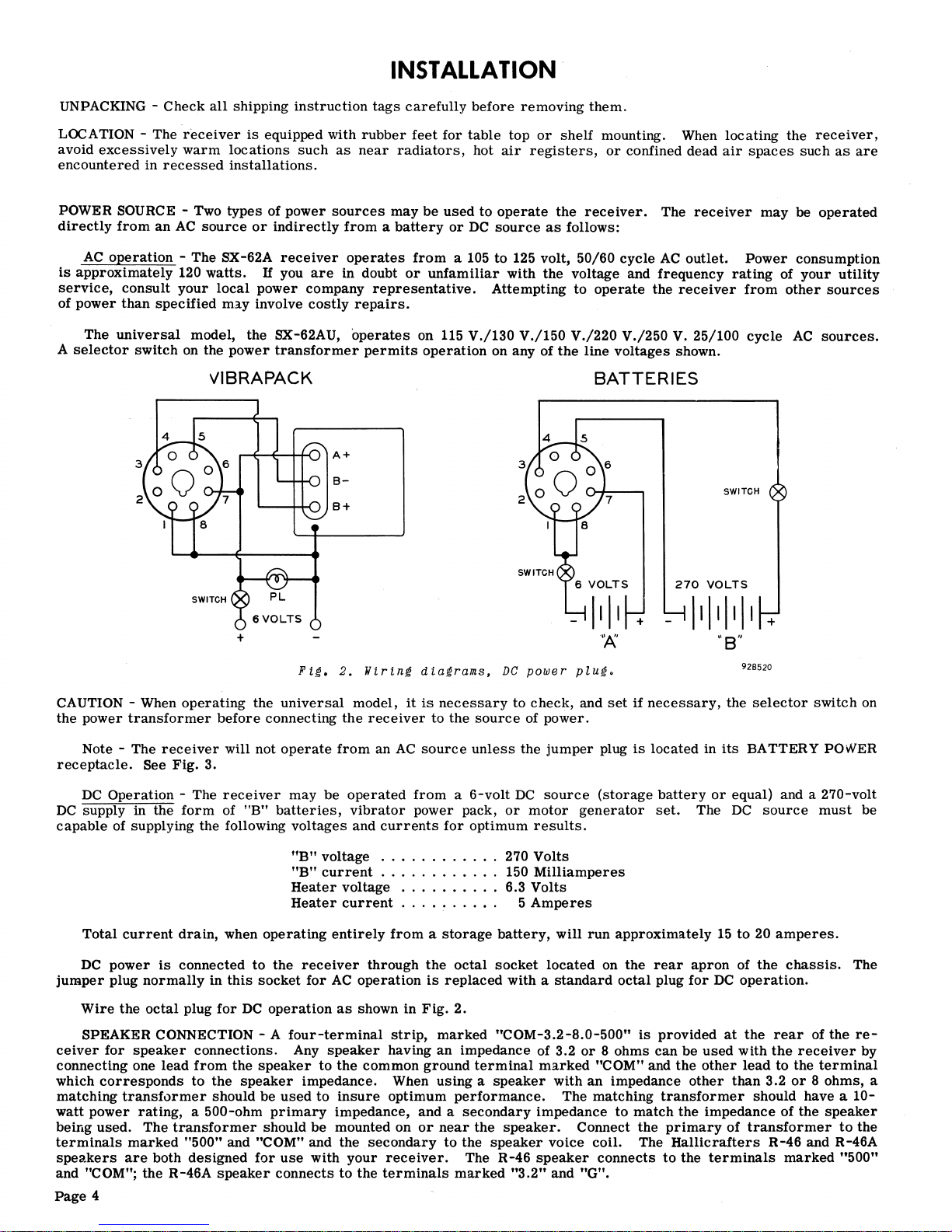
DC
Operation
- The
receiver
may
be
operated
from a 6-volt
DC
source
(storage
battery
or
equal) and a 270-volt
DC
supply in
the
form
of liB"
batteries,
vibrator
power pack,
or
motor
generator
set.
The
DC
source
must
be
capable
of supplying the following
voltages
and
currents
for
optimum
results.
fiB
II
voltage
...........
.
"B"
current
...........
.
Heater
voltage
........
.
Heater
current
. . . . . . . . . .
270 Volts
150
Milliamperes
6.3 Volts
5
Amperes
Total
current
drain,
when
operating
entirely
from a storage
battery,
will
run
approximately
15
to
20
amperes.
DC
power
is
connected
to
the
receiver
through
the
octal
socket
located
on
the
rear
apron
of
the
chassis.
The
jumper
plug
normally
in
this
socket
for
AC
operation
is
replaced
with a
standard
octal
plug
for
DC
operation.
Wire
the
octal
plug
for
DC
operation
as
shown in
Fig.
2.
SPEAKER CONNECTION - A
four-terminal
strip,
marked
"COM-3.2-8.0-500"
is
provided
at
the
rear
of
the
re-
ceiver
for
speaker
connections. Any
speaker
having
an
impedance of 3.2
or 8 ohms
can
be
used
with
the
receiver
by
connecting one
lead
from
the
speaker
to
the
common
ground
terminal
marked
"COM" and
the
other
lead
to
the
terminal
which
corresponds
to
the
speaker
impedance. When
using a speaker
with
an
impedance
other
than
3.2
or 8 ohms,
a
matching
transformer
should
be
used
to
insure
optimum
performance.
The matching
transformer
should have a
10-
watt
power
rating,
a 500-ohm
primary
impedance, and a
secondary
impedance
to
match
the
impedance of
the
speaker
being
used.
The
transformer
should
be
mounted on
or
near
the
speaker.
Connect
the
primary
of
transformer
to
the
terminals
marked
"500" and "COM" and
the
secondary
to
the
speaker
voice
coil.
The
Hallicrafters
R-46
and R-46A
speakers
are
both
designed
for
use
with
your
receiver.
The
R-46
speaker
connects
to
the
terminals
marked
"500"
and "COM";
the
R-46A
speaker
connects
to
the
terminals
marked
"3.2"
and "G".
Page
4
COM
3.2 8.0
IlOO
PHONO
O©O
LICENSE PLATE
th.holllc:roften
CII.
CHICAGO
u.s.A.
o
SE:;:'L
IHA-
I
JUMPER
PLUG
(AC
OPERATION)
OR
RECEPTACLE
FOR
EXTERNAL
DC
SUPPLY.
PHONO
INPUT
CONNECTOR
Fi~.
3.
Rear
view.
o
o
AI
A~
I
GND
ANTENNA TERMINAL
STRIP
92D521-A
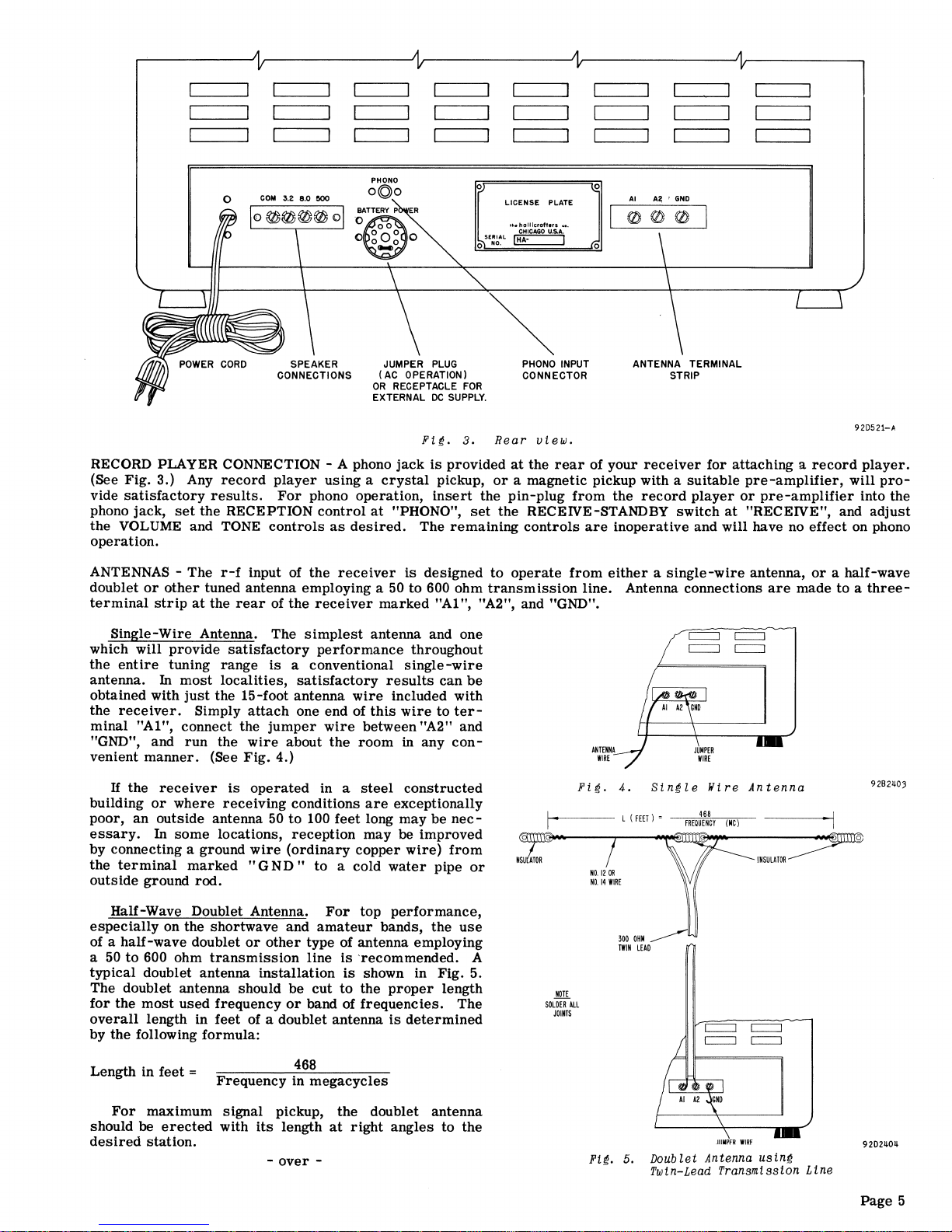
RECORD PLAYER CONNECTION - A phono
jack
is
provided
at
the
rear
of
your
receiver
for
attaching a record
player.
(See Fig. 3.) Any
record
player
using a crystal
pickup,
or
a magnetic pickup with a
suitable
pre-amplifier,
will
pro-
vide
satisfactory
results.
For
phono operation,
insert
the
pin-plug
from
the
record
player
or
pre-amplifier
into
the
phono jack,
set
the
RECEPTION
control
at
"PHONO",
set
the
RECEIVE-STANDBY
switch
at
"RECEIVE", and
adjust
the
VOLUME and TONE
controls
as
desired.
The
remaining
controls
are
inoperative
and
will
have no effect on phono
operation.
ANTENNAS -
The
r-f
input of
the
receiver
is
designed
to
operate
from
either a single-wire
antenna,
or
a half-wave
doublet
or
other
tuned
antenna
employing a 50
to
600 ohm
transmission
line. Antenna connections
are
made
to a three-
terminal
strip
at
the
rear
of
the
receiver
marked
"A1 ", "A2", and "GND".
Single-Wire
Antenna.
The
simplest
antenna and one
which
will
provide
satisfactory
performance
throughout
the
entire
tuning
range
is
a conventional
Single-wire
antenna. In
most
localities,
satisfactory
results
can
be
obtained with
just
the 15-foot
antenna
wire
included with
the
receiver.
Simply
attach
one end of
this
wire
to
ter-
minal
"A1", connect the
jumper
wire
between "A2" and
"GND", and
run
the
wire
about
the
room
in
any
con-
venient
manner.
(See
Fig.
4.)
H
the
receiver
is
operated
in a
steel
constructed
building
or
where
receiving
conditions
are
exceptionally
poor,
an
outside antenna
50
to
100
feet
long
may
be
nec-
essary.
In
some
locations,
reception
may
be
improved
by
connecting a ground
wire
(ordinary
copper
wire)
from
the
terminal
marked
"G
ND"
to
a cold
water
pipe
or
outside
ground
rod.
Half-Wave Doublet Antenna.
For
top
performance,
especially
on the
shortwave
and
amateur
bands,
the
use
of a
half-wave
doublet
or
other
type of antenna employing
a
50
to
600 ohm
transmission
line
is
·recommended. A
typical
doublet antenna
installation
is
shown in Fig. 5.
The
doublet antenna should
be
cut
to
the
proper
length
for
the
most
used
frequency
or
band
of
frequencies.
The
overall
length in
feet
of a doublet
antenna
is
determined
by
the
following
formula:
Length in
feet
=
468
Frequency
in
megacycles
For
maximum
signal
pickup,
the
doublet
antenna
should
be
erected
with
its
length
at
right
angles
to
the
desired
station.
-
over
-
Fi~.
4.
Sin~le
lIire
Antenna
1-1
~.
---
L
(FEET)'
----;F""'REQ;;;i;~:~N8C;;-y
"(M""'C)'----
---~·-11
NOTE
SOLOERALL
JOINTS
Ft~.
5.
INSULATOR
Doublet Antenna
usin~
Twin-Lead Transmission Line
92B2~03
o
92D2~O~
Page
5
 Loading...