

Hallicrafters SX-42 Operating Instructions Manual
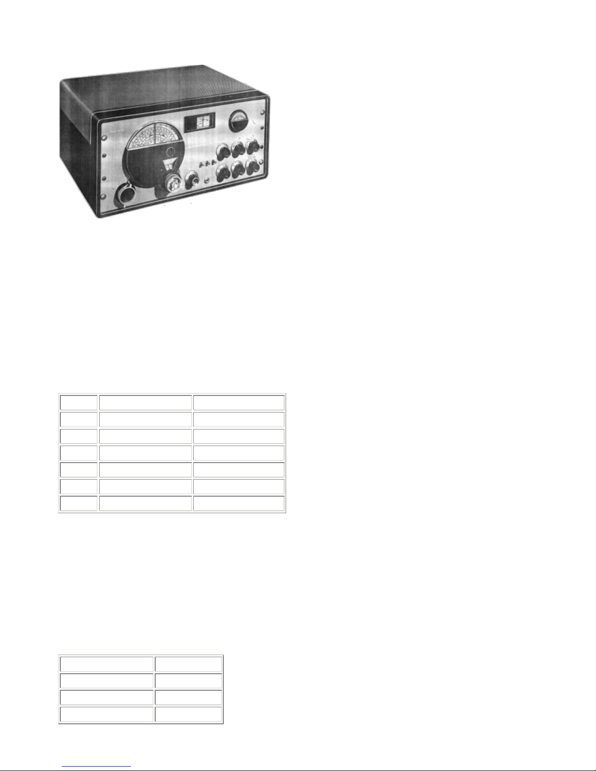
Hallicrafters SX-42 Operating Instructions
Excerpted from SX-42 Owner's Manual, Copyright 1946 Hallicrafters Co.
1. GENERAL
The Model SX-42 is a 15 tube superheterodyne radio receiver designed to provide amplitude modulated (am) reception over the frequency range 540 kc (kilocycles) to 110 mc (megacycles) and high fidelity,
frequency modulated (f-m) reception over the frequency range 27 to 110 mc. Calibrated bandspread is
provided for the 80, 40, 20, 10, and 6 meter amateur bands. The general coverage dial and bandspread dial
are operated from one tuning control which consists of two independent knobs turning on concentric shafts.
A dial lock is provided to lock the unused dial while tuning the receiver. This exclusive Hallicrafters feature
insures accurate tuning and logging.
Frequency Coverage
Band
Coverage
Type of reception
1
540-1620 kilocycles
AM/CW
2
1.62-5 megacycles
AM/CW
3
5-15 megacycles
AM/CW
4
15-30 megacycles
AM/CW
5
27-55 megacycles
AM/FM/CW
6
55-110 megacycles
AM/FM/CW
Adequate overlap is provided at ends of all bands. The receiver as normally supplied is designed to operate
from a 105 to 125 volts 50/60 cycle, single phase source of a-c power. These operating instructions also
cover Universal Models which operate from a 105 to 250 volts, 25/60 cycle single phase a-c source.
2. AC OPERATION
Be sure line voltage is 105 to 125 volts and frequency is 50 to 60 cycles before inserting power cord plug
into power outlet. Be sure all tubes are securely inserted in their proper sockets before receiver power is
turned on. The chart below lists the current and voltage data.
Power Consumption
110 Watts
Frequency
50/60 Cycles
Line Voltage
117 Volts
Line Current
0.93 Amperes

During a-c operation, the shorting plug supplied with the receiver must be in the octal socket on the rear
apron of the chassis.
3. D-C OPERATION
The receiver may be operated from a 6 volt d-c source, generally a storage battery, and a 270 volt d-c supply
in the form of "B" batteries or vibrator type power pack. Consult the chart on power requirements at the end
of this paragraph and provide battery or power pack facilities capable of supplying these demands. The
receiver is connected to the--d-c supply as follows:
1. Remove the octal shorting plug for a-c operation from the socket SO-1 located on the rear apron of the
receiver chassis.
2. Wire an octal plug, as shown in Fig. 10, and plug it into socket SO-l. Use #19 (AWG) wire leads for the
270 volt "B" supply connections to pins #3 and #5, and #'12 (AWG) wire leads for the 6 volt battery
connections to pins #1, #7, and #8. CAUTION: Check the wiring carefully before connecting to the battery
supply. The chart below lists the current voltage data.
"B" Voltage
270 Volts
"B" Current
150 ma.
Filament Voltage
6 Volts
Filament Current
5 Amperes
Total battery drain when operating from a 6-volt vibrator power supply is approximately 16 amperes.
4. OUTPUT CONNECTIONS
Output connections for the speaker are provided for on the rear apron of the chassis. Two output impedances
are available. Either the 500/600 or the 5000 ohm speaker connection may be used according to the output
impedance desired. This arrangement of dual output impedances will accommodate most requirements. The
Hallicrafters Model PM-23 speaker requires 5000 ohms impedance; the Hallicrafters Model R-42, R-44, R75, or R-80 requires 500/600 ohms. However, any standard type, permanent magnet dynamic speaker with
output transformer may be connected to the output terminals. If the permanent magnet dynamic speaker
impedance is unknown, try the 5000 ohm and then the 500/600 ohm impedance, and use the one which gives
the better tone quality and: volume.
5. PHONO INPUT CONNECTION
A receptacle is provided on the rear apron of the chassis for connecting a phonograph record player to the
receiver. This receptacle is designed to accommodate a Cinch, type M-93, pin connector plug.
6. ANTENNA AND GROUND CONNECTIONS
The Model SX-42 is designed for a 300 ohm antenna impedance. The antenna impedance is not critical and
excellent reception can be obtained from an antenna of from 50 to 600 ohm impedance. For maximum
performance, the best possible antenna should be employed.
The antenna terminals on the Model SX-42 are arranged for any type of antenna from those requiring a
ground to those using a transmission line. The transmission type of antenna connects to the A-1 and A-2
terminals whereas a single wire antenna utilizes terminal A-1 for the antenna lead. A-2 and GND terminals
must be connected together and connected to a good ground.
 Loading...