

Hallicrafters SR-150 Operation And Maintenance Manual
SUPPLEMENT
Please help me. I
can still be a great
performer!!
TO
OPERATION AND MAINTENANCE
MANUAL
HALLICRAFTERS
SR-150
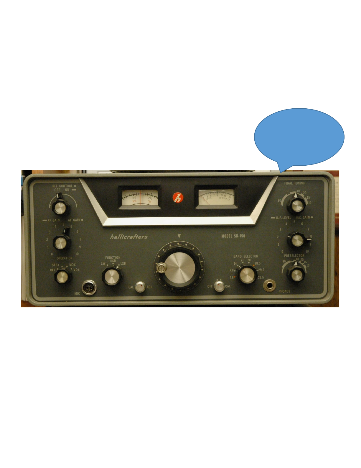
Photo courtesy of W4AWM
By Walter Cates WD0GOF (UPDATE 10/30/2013) 1

SUPPLEMENT TO
OPERATION AND MAINTENANCE MANUAL
HALLICRAFTERS SR-150
INTRODUCTION
The SR-150 was produced by Hallicrafters from 1961 to 1963. It is a 19 tube cw/ssb 80 thru 10 meter
transceiver. The transmitter input power is 150 watts pep ssb and 125 watts cw. The transmitter and receiver
are VFO controlled. Other features include receiver incremental tuning, RIT, allowing the receiver to be tuned 2
KHz on either side of the transmitter frequency, dual conversion, VOX, PTT, CW break in, 100 KHz crystal
calibrator, product detector, combination S METER and RF output meter, and crystal-lattice filter. Both AC and
DC power supplies are available and are a separate component.
Of all the transceivers Hallicrafters produced the SR-150 is arguably the best performer within its range of
functions. In recent years (circa 2013) it has experienced a renaissance in popularity. Once properly refurbished
it is an outstanding performer. It is rare to find one that is original and pristine most have been “improved” to
the point of worthlessness. But with a little tender loving care it can be brought back to life. For those with little
or no experience with the SR-150, where to start, and how to proceed can be a daunting task. One section in this
document deals with this resurrection process. The REFURBISHING AND REPAIR section takes a systematic
approach to rehab. If it is followed in order you will minimize the frustration of restarts and backups. It assumes
a working knowledge of radio and tube circuit theory. For the most part it will lead you to the stage or stages
where faults have occurred. At this point you must have the skills to locate the failed component.
Over the years technical data on this system has scattered to the four winds. The purpose of this document is to
assemble as much technical information as can be found into one clear and easy to read document
This document is available free of charge and can be downloaded from the Yahoo users group
http://groups.yahoo.com/group/HallicraftersRadios/ or the HHI site http://www.w9wze.net/. This document is
the intellectual property of the author, Walter A. Cates, WDØGOF. Unless specifically credited to a contributor
all processes, ideas, drawings, data sheets and opinions contained here are those of the author.
Special thanks to Jim, K9AXN and Randy, WN9D. Their technical input and proof reading comments were
invaluable to the process.
By Walter Cates WD0GOF (UPDATE 10/30/2013) 2

SUPPLEMENT TO SR-150
OPERATION AND MAINTENANCE MANUAL
TABLE OF CONTENTS
INTRODUCTION .................................................................................................................................................................................... 2
1. SR-150 REFURBISHING AND REPAIRING ................................................................................................................................... 5
1-1. RECAPPING; ................................................................................................................................................................................. 5
1-2. RELAYS ........................................................................................................................................................................................ 5
1-3. AFTER MARKET MODIFICATIONS ......................................................................................................................................... 5
1-4. FACTORY UP-GRADES .............................................................................................................................................................. 6
1-5. INITIAL POWER UP .................................................................................................................................................................... 6
1-6. CHECK AND ADJUSTMENT OF OSCILLATORS: ................................................................................................ ................... 6
1-6-1. CARRIER OSCILLATOR: ...................................................................................................................................................... 7
1-6-2. HETERODYNE OSCILLATOR: ............................................................................................................................................. 7
1-6-3. VFO: The VFO is comprised of V9 and associated circuitry, VFO correction circuitry and the RIT/CAL circuitry. ............ 8
1-6-3-1. RIT/CAL ........................................................................................................................................................................................................ 8
1-6-3-2. VFO CORRECTOR ....................................................................................................................................................................................... 8
1-6-3-3. VFO ALIGNMENT ....................................................................................................................................................................................... 8
1-7. RECEIVER TESTING ................................................................................................................................................................... 9
1-8. RECEIVER FAULT ISOLATION ................................................................................................................................................. 9
1-8-1. EQUIPMENT REQUIRED: ................................................................................................................................................... 9
1-8-2. RX FAULT ISOLATION PROCEDURE: ............................................................................................................................... 9
1-8-2-1 RECEIVER TROUBLESHOOTING TABLE. ..................................................................................................................... 10
1-8-2-2 Final receiver test. ............................................................................................................................................................. 11
1-9. TRANSMITTER TESTING ......................................................................................................................................................... 12
1-9-1. TRANSMITTER TESTING EQUIPMENT REQUIRED ........................................................................................................ 12
1-9-2. TRANSMITTER TESTING PROCEDURE ........................................................................................................................... 12
1-9-3. TX DRIVE FAULT ISOLATION ........................................................................................................................................... 13
1-9-4. TX BIAS FAULT ................................................................................................................................................................... 14
2. PRODUCTION RUN UP-GRADES ................................................................................................................................................. 15
2-1. FACTORY REVISIONS PER BULLETIN 1962-2 ..................................................................................................................... 15
2-2. KEY CLICK MOD ....................................................................................................................................................................... 16
3. SUBSYSTEM TECHNICAL INFORMATION .............................................................................................................................. 17
3-1. RIG CLEANING .......................................................................................................................................................................... 17
3-1-1. CHASSIS CLEANING .......................................................................................................................................................... 17
3-1-2. TUBE SOCKET CLEANING KIT ......................................................................................................................................... 20
3-1-3. AIR VARIABLE CLEANING ................................................................................................................................................ 21
3-2. MICROPHONE SELECTION ..................................................................................................................................................... 22
3-3.VFO DRIFT................................................................................................................................................................................... 23
3-3-1. VFO DRIFT TEST ................................................................................................................................................................ 23
3-3-2. RIT ZENER MOD ................................................................................................................................................................. 23
3-4. SR SERIES RIT/CAL ADJ DISCUSSION .................................................................................................................................. 24
3-4-1. SSB RIT OPERATION .......................................................................................................................................................... 24
3-4-2. CW RIT OPERATION & THE SR-150. ................................................................................................................................ 25
3-5. RELAYS K2 & K3 ....................................................................................................................................................................... 26
3-5-1. K2 & K3 SUBSTRATE WARPING. ...................................................................................................................................... 26
3-5-2. K2 K3 CLEANING: .............................................................................................................................................................. 27
3-5-3. NON-STANDARD RELAY REPLACEMENT ....................................................................................................................... 27
3-5-4 K2 WIRING AND PIN OUT .................................................................................................................................................. 29
3-5-5 K3 WIRING AND PIN OUT .................................................................................................................................................. 30
3-6. PA LOADING COIL L32 ............................................................................................................................................................ 31
3-7. RECEIVER GAIN IMPROVEMENT.......................................................................................................................................... 32
3-8. RX GAIN ANOMALY ................................................................................................................................................................ 32
3-9. MIC GAIN AND AUDIO OSCILLATIONS IN THE SR-150 .................................................................................................... 34
By Walter Cates WD0GOF (UPDATE 10/30/2013) 3

3-10. PA NEUTRALIZATION ........................................................................................................................................................... 35
3-11. SR-150 FILTER PASS BAND EMAIL DISCUSSION ............................................................................................................. 36
4. DATA SHEETS .................................................................................................................................................................................. 38
4-1. VFO FREQUENCY CORRECTION ........................................................................................................................................... 39
4-2. RECEIVER PERFORMANCE: ................................................................................................................................................... 40
4-3. TRANSMITTER PERFORMANCE: ........................................................................................................................................... 41
5. PERFORMANCE SPECIFICATIONS ............................................................................................................................................ 42
By Walter Cates WD0GOF (UPDATE 10/30/2013) 4

1. SR-150 REFURBISHING AND REPAIRING
SO YOU JUST GOT AN SR-150 FROM E-BAY OR SOMEONE THAT SAID “IT
WORKED FINE THE LAST TIME I TURNED IT ON”. NOW WHERE DO YOU
START? THE FOLLOWING PROCESS HAS EVOLVED OVER YEARS OF
REFURBISHING THE SR-150. IT SHOULD BE FOLLOWED IN THE ORDER IT IS
WRITTEN. THIS PROCEDURE IS DESIGNED TO PROGRESS IN AN ORDERLY
MANNER TO MINIMIZE RUNNING IN CIRCLES. BE AWARE THIS IS NOT
SOMETHING THAT IS ACCOMPLISHED WITH GREAT SPEED. THE AVERAGE
TIME TO COMPLETION IS AROUND 60 HOURS. SOME HAVE TAKEN AS MUCH
AS 200 HOURS, SOME AS FEW AS 20 HOURS.
A complete cleaning and mechanical inspection is always advised. Cleaning of the rotary switches and the
relays is of particular importance. Refer to the RIG CLEANING section for details. Look closely for broken or
burned components. Check the rotation of the controls and mechanical stops of the main tuning dial. Try to
eliminate the mechanical problem first. Inspect L32 for heat deformation on the close wound end. This is a high
failure rate item when the rig is mistuned or misused in TX mode. See the PA LOADING COIL L32 section for
repair details.
1-1. RECAPPING;
There are only four capacitors that are considered must replace components. They are C63, 5uf/25v, C100,
5uf/25v, C114, 10uf/50v and C115, 2 X 30uf/350v. Capacitors C63, C114 and C115 each carry heavy current
loads. Therefore the ESR rating of replacements is important. They should have an ESR rating of 1.0 ohms or
less. ESR’s of 0.3 ohms and lower are available. This is not a place to save money. C115 is a dual cap. There
are sources for this capacitor, but be careful. Some manufactures of these parts use inexpensive low quality
parts. Don't buy from suppliers who will not quote or guarantee the ESR rating. Very low ESR individual
capacitors are readily available. So replacing the dual cap with two capacitors under the chassis is sometimes a
better solution. Generally speaking shotgun replacement of the paper caps is not recommended.
1-2. RELAYS
Relays K2 and K3 are the most problematic components in the 150. Relay K1, not so much, usually all it needs
is contact cleaning. Relays K2 and K3 in parallel provide approximately 380 ohms resistance for the cathode of
V13. So the common 12vdc relay will not substitute for them. Years of misuse and spraying with contact
cleaner has warped the contact substrate of K2 and K3. Rule #1 for relays is never spray relays with anything.
Rule #2 never use sandpaper on the contacts. You can test them in the rig using a VOM, two clip leads and a 10
volt supply. More often than not they need to be removed repaired and reinstalled. Go to RELAY TEST AND
REPAIR section for information on how this is accomplished. They need to be verified as operational before
you proceed to the next step in this process.
1-3. AFTER MARKET MODIFICATIONS
If you find any modifications, re-wirings or added components remove them and return the rig to the original
configuration.
By Walter Cates WD0GOF (UPDATE 10/30/2013) 5

SR-150 REFURBISHING AND REPAIRING CONTINUED:
1-4. FACTORY UP-GRADES
It is highly recommended to up-grade the SR-150 to the production run 7 level. See the chart in the section
PRODUCTION RUN UP-GRADES for a list of changes. It is recommended to upgrade to run 7 level before
you start electrical testing.
1-5. INITIAL POWER UP
First and of critical importance, you must have a power supply that has been tested and meets all the original
specifications. You will not be transmitting power until late in this process so temporarily replace the 3 amp sloblow fuse with a 3 amp normal delay fuse. It is not necessary to start with a low AC voltage and increase the
voltage over time to cook the rig. There are no domino circuits in the SR-150. If you have a short somewhere,
you may cook a resistor and it will smell bad but it will lead you straight to the problem. So set all the gain and
drive controls to minimum. Every time you turn on your SR-150 all these controls should be at minimum. The
STANDARD PRE-POWER UP CONFIGURATION will always be: all gain controls set to minimum, RIT
off, RIT CONTROL at mid-range, CAL ADJ at mid-range, CAL OFF, preset the PRESELECTOR to the
approximate position in the band you will be operating, set the FINAL TUNING to the approximate position in
the band you will be operating and set the FUNCTION switch to either USB or LSB depending upon which
band you will be testing. Ok it is time apply power. Attach the power supply and plug it in. Set the operation
switch to STBY. Now let it sit there for 10 to 15 minutes. Locate R95, 2500 ohm, 10 watt resistor connected to
V12. The voltage at one end should 150vdc and 250 – 280vdc at the other. If not you have a fault that must be
fixed before you proceed. Otherwise the only thing we need to adjust at this time is rough set the bias voltage.
On the underside of the Final tubes locate the tie point of R105 (10K) and L36. This is where we will measure
the bias voltage in the receive mode. Set your meter on the 200vdc range. Now adjust the bias adjust control on
the power supply for -105vdc. Turn the power off; plug your meter into the red (+) and blue (-) test jacks on the
power supply. Set the meter on the 2vdc range. Set the function switch to LSB, Connect a mic and set the RF
GAIN and MIC GAIN to minimum. Turn the power back on. Key the mic. The meter should read less than
0.5vdc. If it reads higher than 0.5 VDC adjust it down with the bias control (This is a preset voltage setting, later
in the transmitter tests the bias setting will be set to its operating level). If you cannot adjust it or it is very high
then you have a problem in the final PA or bias divider and this must be corrected before you proceed, go to the
TX BIAS FAULT section. If all is well with the bias you are now ready to proceed to the CHECK AND
ADJUSTMENT OF OSCILLATORS section.
1-6. CHECK AND ADJUSTMENT OF OSCILLATORS:
Before starting any receiver or transmitter troubleshooting or RF or I.F. alignment it is imperative that
the xtal oscillators and the VFO are precisely on frequency. If you will devote the time to these considerations
you will be rewarded with a rig that performs as well as any modern rig. A frequency counter and scope are
required. The procedure in the book will work ok, but will compound errors. If you get all the oscillators “on
freq” with proper output levels individually, then all else will fall into place. Do not make any adjustments until
the rig has been on for at least 30 minutes. Optimize the VFO last to insure it is stable. Do not hurry. Take your
time, these processes are critical.
By Walter Cates WD0GOF (UPDATE 10/30/2013) 6

SR-150 REFURBISHING AND REPAIRING CONTINUED:
1-6-1. CARRIER OSCILLATOR:
The carrier oscillator is comprised of V10 and its associated circuitry. First thing is to check the output of the
carrier osc in both USB and LSB modes. After warm up you should have approximately 30 Vpp on pin 7 of
V6. Now adjust T4 for max. The voltage on pin 4 or 3 of T4 should be 9 Vpp. If these voltages are more than
10% low then you most likely have a fault in the oscillator and this fault must be corrected before you proceed.
Once you are satisfied with the oscillator output set the function switch to USB. Connect a scope to pin 7 of V6
to monitor the output voltage of the osc. Connect the frequency counter to either pin 4 or 3 of T4. You will find
that if you adjust T4 in one direction from the peak the signal drops off very fast. In the other direction it falls
more slowly. T4 should be adjusted about 2% to 5% off peak toward the slow fall off side. Switch back and
forth from USB to LSB to insure both oscillators start without any hesitation. In USB mode adjust C106 for
exactly 1651.70 KHz. Switch to LSB mode and adjust C103 for exactly 1648.1 KHz. Adjustment of T4 and
C106 and C103 can interact. Re-check the output voltage and re-check the frequency back and forth several
times to insure that everything is stable and there is no hesitation in the oscillator startup.
1-6-2. HETERODYNE OSCILLATOR:
The Het Osc is comprised of V8 and its associated circuitry. This oscillator is the most troublesome of the three.
There are not any adjustments to pull the frequency of each xtal. So if you do not have a box of spare xtals you
are rather limited in what you can do to put it precisely on frequency. First thing, check the oscillator output.
Connect the scope to the tie point of C80 and CR2 which are located in the cathode ckt of V8. The minimum
peak to peak voltages for each band should be: 80 meters 10 Vpp, 40 meters 11.5 Vpp, 20 meters 6 Vpp, 15
meters 5.5 Vpp, 10 meters (all 4 bands) 5.0 Vpp
If the output does not meet these minimums then this repair must be accomplished before proceeding. Once you
are satisfied with the oscillator output disconnect the scope and connect the frequency counter to the tie point of
C80 and CR2 and check the frequency on each band. If the xtal frequencies are all high or all low then
swapping out C74, C 76 and C77 may bring them back in spec. With the four 10 meter xtals you are pretty
much stuck with where ever they are unless you have a bag of xtals to swap. For the 80, 40, 20 and 15 meter
bands, each band has a warping cap (C73, C72, C71 and C70 respectively). These warping caps can be swapped
out to pull individual xtals on to frequency. The end unit frequency spec is + or – 3 KHz at any dial point across
any band. With the VFO and Carrier oscillators dead on whatever error you have in the heterodyne oscillator is
what you will have to live with
By Walter Cates WD0GOF (UPDATE 10/30/2013) 7

SR-150 REFURBISHING AND REPAIRING CONTINUED:
1-6-3. VFO: The VFO is comprised of V9 and associated circuitry, VFO correction circuitry and the RIT/CAL circuitry.
1-6-3-1. RIT/CAL
The RIT/CAL ckts are used change the bias voltage on a varicap in the VFO. This is used to make minor
corrections to the VFO frequency. The supply for the RIT/CAL ckt is the regulated 150vdc line. The 150vdc
regulated line by normal standards is pretty stable. The voltage divider for the RIT/cal ckt is isolated from the
reg 150v line by a 180k resistor. The leads from the divider ckt wonder back and forth from the front panel to
Relay K1 and back to the VFO. All this boils down to lots of stray pick up. There is a simple solution to the
problem (drawing located in SUBSYSTEM TECHNICAL INFORMATION section). Replace R81 (180K) with
an 82K resistor and parallel C100 with a 1N4742 zener diode. This will lower the dynamic impedance at the
feed point of the CAL/RIT divider from approximately 14k ohms to 5 ohms. This modification is a highly
recommended option. If you decide to perform this option it must be done before you proceed with the
alignment of the VFO. Set the RIT lever switch to off, adjust the RIT control to the center of its rotation. Set the
CAL control to the center of its rotation. This is the setting for these controls throughout all testing unless
otherwise noted. Set the main tuning to 300 on the black scale. Connect the frequency counter to the tie point of
R15 and C83 (in the cathode ckt of V9B). Fine tune the main tuning for 4550.0 on the counter. Rotate the CAL
control to max ccw and note the counter reading. Rotate the CAL max cw and note the counter reading. The
difference from ccw to cc rotation should be minimum 3 KHz, maximum 4 KHz. An in-depth discussion on the
RIT action and setting is in the SUBSYSTEM TECHNICAL section.
1-6-3-2. VFO CORRECTOR
The VFO correction ckt corrects for the frequency off set between USB and LSB (NOTE: CW operates in the
USB MODE). Before the VFO is aligned it must be established that the correction ckts are working properly.
Connect the frequency counter to the tie point of R15 and C83. Set the function switch to LSB and record the
VFO frequency any band any dial setting. Switch to USB and the frequency should drop approximately 3600
Hz. Now adjust C96 to insure that you can get at least a 4000 Hz difference between USB and LSB. If you can,
then adjust it for a difference of exactly 3600 Hz. If you cannot then there is a fault in the corrector ckt that must
be repaired before you can continue with the VFO alignment.
1-6-3-3. VFO ALIGNMENT
Before starting the VFO alignment go to the SYSTEM TROUBLESHOOTING AND TESTING section and
perform the VFO DRIFT TEST.
Connect the frequency counter to the tie point of R15 and C83 (C83 is in the cathode ckt of V9B). Record the
VFO frequency every 100 KHz from 0 to 500 (black scale). A data sheet is provided in the DATA SHEET
section with the data points and the spec frequencies. You may want to make several copies of the data sheet.
If the actual frequency consistently falls above or below the spec frequency adjustment of trimmer C87 is
indicated. Move the dial to the black 500 index mark (be sure you are looking head on at the dial to eliminate
parallax error). Adjust C87 for exactly 4.3519 MHZ. Rerun and record the 6 data points again. If at the
Ø or the 500 index mark you are more than 1 KHz off, tracking of C87 and L27 is required. The original
manual spec at this point is 3 KHZ. But it is normally not difficult to get it right on. So why not try. Adjust
the tuning dial to the black 500 and adjust L27 for 4.3519 MHz. Adjust the dial to the black Ø and adjust C87
for 4.8519 MHZ. You may have to repeat this several times to get it correct. Under correcting or overcorrecting
at one end or the other is sometimes required to get it to fall in. Rerun and record the data. If any of the mid
points fall more than 3 KHz from spec knifing of C32A is indicated (I use 1 KHz for my shop spec). Knifing
should never be attempted on the SR-150 unless you are very skilled at knifing. C32A is fragile and can be
destroyed very easily. You can split the difference. That is move the end points half the max error in the
opposite direction of the error.
By Walter Cates WD0GOF (UPDATE 10/30/2013) 8

SR-150 REFURBISHING AND REPAIRING CONTINUED:
1-7. RECEIVER TESTING
All of the receiver testing will be accomplished by performing tests outlined in the RECEIVER FAULT
ISOLATION section. The Hallicrafters spec states the receiver sensitivity as 1uv signal in for 20db signal plus
noise to noise. The gain is specified at 1uv in for ½ watt audio output. It is quite common for the SR-150 to
meet both of these specs at 0.5uv. I have seen quite a number achieve spec at 0.2uv.
1-8. RECEIVER FAULT ISOLATION
1-8-1. EQUIPMENT REQUIRED:
HF RF signal generator capable of 0.5 microvolts to 300 millivolts and covering 1600 KHZ to 7.3 MHZ Audio
output meter (similar to General Radio 1840A).
Scope 100 MHZ or better with 1:1 and 10:1 probes or switchable probe.
Audio oscillator with 600 ohm output Z0 capable of from 0.7 millivolts to 15v peak to peak output.
1-8-2. RX FAULT ISOLATION PROCEDURE:
There is not anything inherently clever about this process. What it does offer is signal injection levels and
output results gathered from dozens of tests performed on SR-150’s over 12 years. For those who wish to
expound on the evil effects of probe loading and ckt miss-matches, I concede you are correct, it does happen.
But the process works, it is repeatable and simple to follow. Throughout this process we will be injecting
signals at different points throughout the radio and monitoring the audio output from the receiver. In all cases
the output we are looking for is 1 watt of audio output. It is recommended to use an audio output meter. This is
helpful because audio output meters similar the GR 1840A allows for dB measurements as well as power
output. Any 10 watt resistive load may be used in place of the audio power meter. When using an alternative
load you will need to monitor the voltage across the load. Then you will have to convert the RMS or peak to
peak voltage to watts depending upon your use of a scope or RMS voltmeter.
Read the entire procedure thru before you start. To eliminate problems caused by the AGC install a clip
lead from the tie point of R20, 220k and R116 820k and ground. These resistors are located on the 4 lug
terminal strip adjacent to the socket of V17. Set up the receiver on the 40 meter band at 7.3 MHz. Adjust the RF
GAIN and AF GAIN to max. This process is written specifically for resurrecting long dead rigs. Multiple faults
are assumed.
Note; There were 7 production runs of the SR-150. The following signal
levels apply directly to runs 3 through 7. Production runs 1 and 2 will
require as much as 10% more signal for the same audio output levels.
Refer to SECTION-2 for details to determine which production level you
have. IT IS HIGHLY RECOMMENDED TO UPGRADE TO LEVEL 7.
By Walter Cates WD0GOF (UPDATE 10/30/2013) 9

SR-150 REFURBISHING AND REPAIRING CONTINUED:
Injection
point
Injection
signal
Injection
level**
***
Audio
out
If OK go to next step. If not
check suggestions below
1
Pin 1 V13
1KHz
15vpp
1
watt
V13 and associated circuitry,
check K1 switching
2
Pin 8 V11
1KHz
0.3vpp
1 wt
V11 and associated circuitry
3
Bottom
C64
1KHz
0.5vpp
1 wt
Shielded wire, R91 and grid ckt
of v11
4
Pin 1 V6
1650KHz
0.015v
1 wt
Check pin 7 V6 for 25vpp of
injection from carrier osc, V6 or
its associated circuitry.
5
Pin 2 V5
1650KHz
0.01v
1 wt
V5 and its associated circuitry
6
Pin 2 V17
1650KHz
200uv
1 wt
V17, FL1 and their associated
cktry
7
Pin 2 V4
6.2MHz*
300uv
1 wt
V4 and associated cktry
8
Pin 2 V3
6.2MHz*
200uv
1 wt
V3 and associated cktry
9
Pin 7 V2
7.3MHz*
10uv
1 wt
Check relay side of C27 for at
least 10vpp of carrier injection,
otherwise V2 and associated
cktry is suspect.
NOTE
If step 9 is successful perform a pre-alignment at this point.
First reduce the drive from the signal generator until you have ½ watt audio output.
Insure the main tuning is peaked, then adjust T1, T2, and T3 (top and bottom slug) for max audio
output. Throughout this process insure the main tuning is peaked. Keep the audio output at or below ½
watt by adjusting the injection level. This is not intended to be the final I.F. alignment but will enhance
later alignment and final adjustments.
10
Tie point
C17 & L10
7.3MHz^
40uv
1 wt
6MHz trap, band switch or K2
11
Pin 6 V1
7.3MHz^
1uv
1 wt
V1 and associated cktry
12
J1
7.3MHz
1uv
1 wt
Circuitry between J1 and V1
1-8-2-1 RECEIVER TROUBLESHOOTING TABLE.
^ Some adjustment of the main tuning and PRESELECTOR will be required.
*Some adjustment of the main tuning will be required to get max peak
**Use X1 probe unless otherwise noted.
***Voltages are RMS unless otherwise noted.
By Walter Cates WD0GOF (UPDATE 10/30/2013) 10

SR-150 REFURBISHING AND REPAIRING CONTINUED:
1-8-2-2 Final receiver test.
With the ground still connected to the AGC line. With the equipment set up as in step 12 in the table;
1, remove the gnd from the AGC line. If the audio output decreases more than 2db or goes away you have a
fault in the AGC and this fault must be cleared before continuing.
2, Connect the gnd lead to the tie point of R22 and C39 (this is in the cathode of V4). If the audio output from
the receiver increases with the grounding of this point then you have a defective R10 (RF GAIN POT). You can
have up to 1db difference and the receiver will function properly. More than 1db and the sensitivity will be
adversely affected. Also, The S meter will not function correctly. See the section on RX GAIN ANOMALY for
aid in clearing this fault.
You are ready to
proceed to the
TRANSMITTER
TESTING
section.
By Walter Cates WD0GOF (UPDATE 10/30/2013) 11

SR-150 REFURBISHING AND REPAIRING CONTINUED:
1-9. TRANSMITTER TESTING
1-9-1. TRANSMITTER TESTING EQUIPMENT REQUIRED
Wattmeter/load 50 ohm 250 watts full scale
Scope 100 MHz bandwidth
Microphone dynamic 600 ohm
Multimeter 2 VDC full scale and 10 VDC full scale recommended Optional
telegraph key
1-9-2. TRANSMITTER TESTING PROCEDURE
Back in paragraph the 3 amp slo-blow fuse was replaced with a 3 amp normal delay. It is now time to re-install
the 3 amp slo-blow fuse. Set the main tuning dial to 7.25 MHz. Set the band switch to 40 meters. Set the rest of
the controls to the STANDARD PRE-POWER UP CONFIGURATION. Set your meter to the 2 VDC full
scale range and plug it into the red (+) and blue (-) test jacks on the power supply chassis (this is to monitor the
PA plate current). Connect a wattmeter/50 ohm load to the antenna jack of the transceiver. Set the
OPERATION switch to STBY and allow 15 to 20 minutes for warm-up.
Earlier in this process the –bias was rough set. Now it needs to be set more precisely. Set OPERATION
switch to either USB or LSB, ensure MIC GAIN and RF GAIN are at Ø. Attach your mic and key the
transmitter with the mic. Adjust the BIAS ADJ control on the back of the power supply for a reading of Ø.7
volts (This indicates 70 milliamps of plate current) on the meter plugged into the power supply. WARNING;
keep your eyes on the meter as you key the mic. Quickly un-key the mic if the meter pegs. If you cannot adjust
the bias or it pegs you have a problem in the PA or bias voltage divider ckt. This may be a tube or a DC
problem. Check V14 and V15. Then check the voltages on V14 and V15. This fault must be cleared before you
can continue, go to the TX BIAS FAULT section for more information. If you are able to set the bias to 0.7
VDC observing the meter and adjust the BIAS ADJ control to see if you can get 1.5 VDC on the meter.
Quickly return the setting to Ø.7 vdc. If you are unable to get 1.5 VDC then one or both of you final tubes are
weak. Replace them with a matched pair. If replacing the tubes does not clear the fault then you have a problem
with the HV, B+, screen voltage or bias. This fault must be cleared before you continue.
The next series of tests will be conducted in the MOX, CW mode. You will need to switch the FUNCTION
switch from LSB to CW quite often. You MUST keep the transmit duty cycle short. I find it easier to plug a key
into the key jack on the rear of the transceiver. Then you can set the FUNCTION switch to the CW position and
leave it there and press the key when you want power. This saves wear and tear on the FUNCTION switch and
reduces the chances of leaving the transmitter keyed to long. For the remainder of the tests when you are
instructed to “key the transmitter” you will either switch the FUNCTION switch from LSB to CW or press the
key.
Assuming you have properly set the STANDARD PRE-POWER UP CONFIGURATION and are in STBY
tune the main tuning and band switch for 7.25 MHz. Switch to MOX and key the transmitter. Set the meter to
the 10 VDC range. Observe the plate current while advancing the RF GAIN. Do not let the plate current exceed
250 mills (2.5 VDC on the meter). If you do not get an increase in plate current advance the RF LEVEL to the 3
o’clock position. Adjust the PRESELECTOR and FINAL TUNING controls to find a peak in the current. Keep
the plate current below 250 mills by reducing the RF LEVEL as needed. If you are unable to get an increase in
plate current proceed to the TX DRIVE FAULT ISOLATION subsection. This fault must be cleared before you
continue.
By Walter Cates WD0GOF (UPDATE 10/30/2013) 12

SR-150 REFURBISHING AND REPAIRING CONTINUED:
When you clear the fault return to this point in the process. If you got the peak in the plate current, key the
transmitter again, adjust the FINAL TUNING for a dip in plate current. As the dip occurs you should get an
increase in power output. If you get no dip or if the power peak and current dip do not coincide it means the PA
needs to be neutralized. We won’t worry about neutralization at this point. Keep the transmitter duty cycle as
short as possible at all times. Observe the preselector setting. The pointer of the PRESELECTOR control
should be in the center of the 40 meter bar. If not move the pointer to the center of the bar, key the transmitter
and peak L10 and L40 for max power out. Key the transmitter and re-peak the PRESELECTOR and the PLATE
TUNING. Key the transmitter and momentarily advance the RF LEVEL to max while observing the wattmeter
you should get between 40 and 100 watts. Recheck the location of the PRESELECTOR pointer and repeat as
necessary to get it centered. At this point you have proven 80% of the transmitter circuitry. Now check the rest
of the bands. You will need to adjust the driver grid and plate coils on each band. Set the PRESELECTOR
pointer to the center of the band segment and the main tuning to 250 on the black scale. L11, L41 – 80 meters
L9, L39 – 20 meters
L8, L38 – 15 meters
L7, L37 – 10 meters (you will only test the 28.5 band at this time; most rigs don’t have the other xtals anyway.)
Do not worry about low power at this time. If you can get 40 watts or better you are good at this point. If you
have a band that doesn’t function then the fault most likely is in the band switch, the driver grid or plate coils or
plate loading ckt. Those faults must be cleared before you proceed. You are now ready to neutralize the PA and
perform the overall alignment. A precise neutralization procedure can be found in the SUBSYSTEM
TECHNICAL INFORMATION section of this document. There are still a few ckts you have not proven. A full
alignment will proof the rest of the system. Go to Section 8 of your Hallicrafters INSTALLATION AND
OPERATING INSTRUCTIONS manual for the complete alignment procedure. You may check but need not
perform the procedures in subsections 8-3, 8-10, 8-12, 8-14, 8-16 and 8-17. These steps are complete now. You
will find the setup for VOX in section 5 of the Hallicrafters manual. The RECEIVER and TRANSMITTER
performance data sheets In the DATA SHEETS section contain the minimum performance standards for the
unit.
1-9-3. TX DRIVE FAULT ISOLATION
The receiver works well but there is no transmitter power out. If the receiver does not work you must make it
work first, go to RECEIVER FAULT ISOLATION.
We will start at V7 the transmitter mixer.
Set the STANDARD PRE-POWER UP CONFIGURATION. Set the main tuning to the black scale 400. Select
the 40 meter band. Connect the X10 scope probe to Pin 1 of V7. Remove V9 from its socket. Power up and set
the OPERATION switch to MOX. Allow 5 minutes warm up then key the transmitter. You should see a signal
of approximately 3 Vpp on the scope. Move the scope probe to the frequency counter. The counter should read
13.5 MHz. If the signal is not there or not close to the proper frequency you have a problem in the HET osc or
the CR2 switching circuitry.
If the signal is correct unkey, power down, replace V9 and pull V8. Power up, warm up, move the scope probe
to the scope and key the transmitter. You should see a signal of approximately 5 Vpp on the scope. Move the
probe to the frequency counter, it should read very near 6.1 MHz.
By Walter Cates WD0GOF (UPDATE 10/30/2013) 13

SR-150 REFURBISHING AND REPAIRING CONTINUED:
Unkey the transmitter and power down. If the signal is not correct and given that we have already demonstrated
nominal receiver operation the possible faults have been narrowed. These possibilities are: relay K1, T6 and its
diode switching and the FUNCTION and OPERATION switches wiring. This fault must be cleared before
continuing.
If both signals were there reinstall V8. Connect the probe to the scope and Pin 2 of V16. Power up, warm up,
and key the transmitter. You should see a 2.5 volt signal on the scope. Move the probe to the frequency counter.
The counter should display the transmit frequency of the band you are on. Unkey and power down. If you got
the signal but it is off frequency or there was no signal then there is a fault in V7. If the signal is good there is a
fault in the driver or finals.
1-9-4. TX BIAS FAULT
If you are unable to set the BIAS adjustment properly there are four possibilities: bad tubes, bias divider,
function and operation switch, and power supply.
1, First locate R126 (33K). Set your meter to the 200v full scale range and connect the negative lead to R126.
That is the end that connects to R125 (100K). Set the controls to LSB, STANDBY. Now run the BIAS ADJ
control from end to end. The voltage should run from approximately -85 VDC to -130 vdc. If it does not you
have a power supply, a function or operation switch or switch wiring error fault.
2, If that test is good set the BIAS ADJ control for -105 VDC on the meter. With the function switch in the LSB
position move the operation switch to MOX. If the -105 does not change the operation switch is ok.
3, Return the operation switch to STANDBY and move the function switch to CW. If the -105 VDC is still -105
VDC the function switch is good.
4, Move the meter to the tie point of L36 and R105. In the STANDBY/LSB mode measure the voltage when
you adjust the BIAS ADJ control from end to end. These end to end measurements should match the end to end
measurements you got in step 1. If they do not you have a shorted final tube, wiring fault or bad resistors in the
BIAS DIVIDER.
5, Once you have verified proper operation set the bias voltage per step 2 and continue in the TRANSMITTER
TESTING PROCEDURE section
By Walter Cates WD0GOF (UPDATE 10/30/2013) 14

SR-150 REFURBISHING AND REPAIRING CONTINUED:
1st 6 digits of
Serial #
415000- = run 1
MODIFICATION
(
REASON FOR MODIFICATION
415001
Add capacitor C14, 100pf 500v plastic mica ( part # 482161101)
between the wiper arm of QT Gain control R96 and ground
Change capacitor C163 (27mmf) to 18mmf, 500v plastic mica (part
# 482-132180)
Improves by-passing action, eliminates possibility of
1650KC regeneration in receive position
This change facilitates carrier balance adjustment. (Note added
by WD0GOF in 2013; This was mandatory only in run 3 and
later.)
415002
Change C62 and C65 (470pf) to 0.001uf, 500v ceramic disc.
Change capacitor C116 (0.005uf) to 0.001uf, 500v ceramic disc.
Add silicon diode CR12, 1N456 between R1 and the control grid,
pin 6 of V1. (Cathode of CR12 to R1) Change resistor R100
(4700ohms) to 2700 ohms.
Change resistor R101 (2700 ohms) to 4700ohms.
Change resistor R116 (1.5 meg ohms) to 820K ohms.
Reshapes the receiver audio response to reduce the highs.
Improves AGC action and also provides complete cut-off of the
RF tube during transmitting.
415003
Change capacitor C76 (4.7pf) to 10pf, 500v plastic mica. Change
resistor R64 (47k ohms) to 220K ohms. The lead that was
connected to ground is now connected to pin 3 of V8.
Capacitor C100 is moved to the tie point of R81 and R82 and
ground. A ground lug is installed under the adjacent escutcheon
mounting screw
Ensures starting of the heterodyne oscillator if the crystal has a
tendency to be sluggish.
Corrects chirp when going from receive to transmit.
415004
Add two resistors, R161 and R162, one each to the grid, pin5 of
V14 and V15 both terminated at R105. These resistors are both 10
ohms, ½ watt, 10%.
Removes parasitics noticed in some unit when operating on 15
meters
415005
Change R123 (150 ohms) to 10K ohms
Change C166 (0.005uf) to 0.001uf, 500v, ceramic disc.
Add C181, 0.01uf, 20% ceramic disc between the terminal strip
connection of R85 and the ground lug of the same strip.
Change C113 (0.01uf) to 0.005uf, 500v, ceramic disc.
See section 2-2 for details of click mod
Improves transmitter audio response.
Reduces spurious signal at 21425KHz receive and reduces motor
boating when sidebands are switched.
Removes transmitted “click” from SR-150 when switching from
transmit to receive.
415006
Replace R110 100k ohms with 270uh choke designate L43
Improves grid bias and grid drive to V16.
2. PRODUCTION RUN UP-GRADES
2-1. FACTORY REVISIONS PER BULLETIN 1962-2
By Walter Cates WD0GOF (UPDATE 10/30/2013) 15
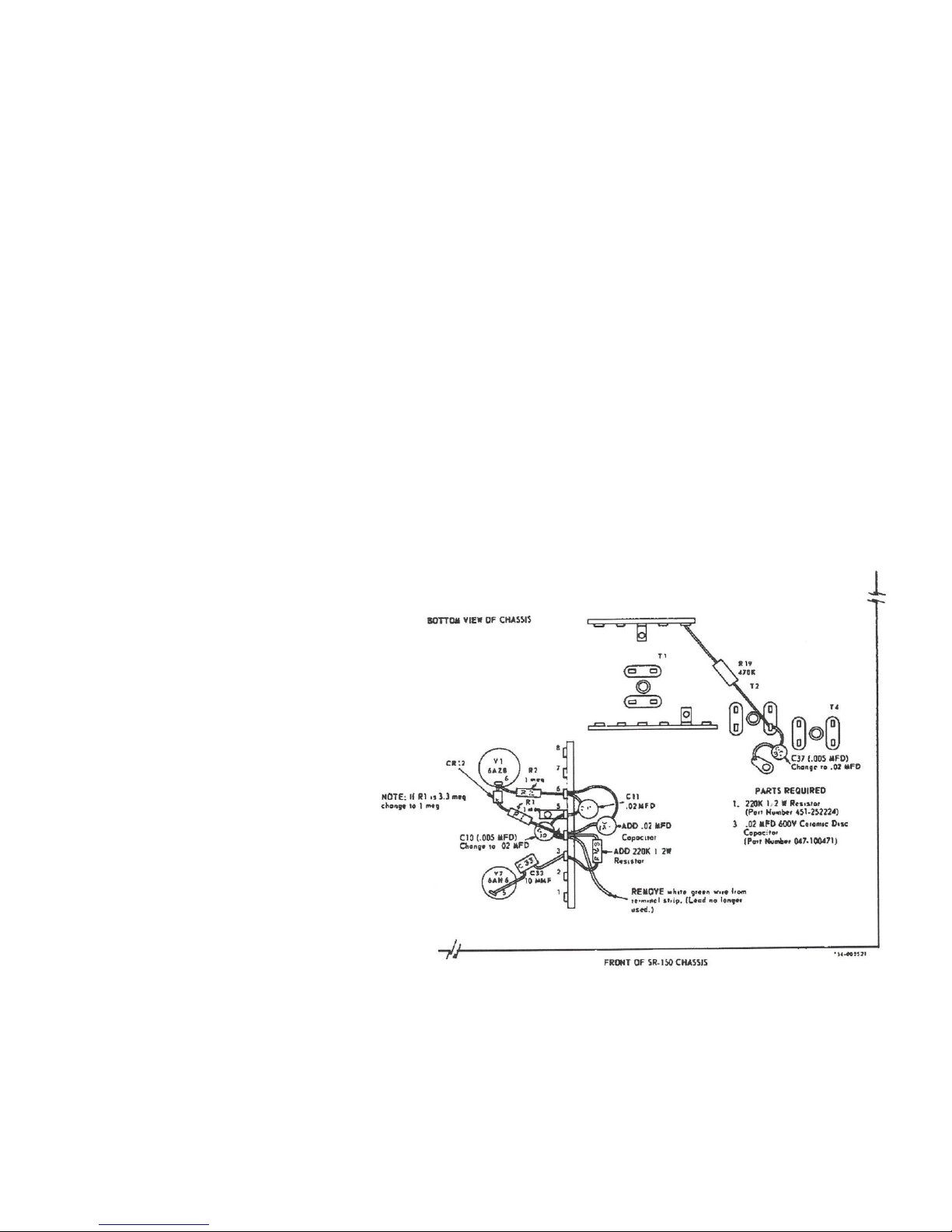
2-2. KEY CLICK MOD
The following procedures outline the modifications necessary to remove
the transmitter “click” from the SR-150 Transceiver, when switching from transmit to
receive.
1. Remove white/green wire from terminal 4 of terminal strip near tubes V1
and V7. (Junction of R1, 1 Meg and C10, .005 uf)
2. Replace capacitor C10 (.005 uf) with a .02uf disc capacitor. (Connected
between terminals 4 and 5 of terminal strip.)
3. Add a .02 uf disc capacitor between terminals 4 and 6 of terminal strip.
This will be designated C180
4. Add a 220K ohm, ½ watt resistor between terminals 3 and 4 of terminal
strip. This will be designated R163
5. Replace capacitor C37 (.005 uf) with a .02 uf disc capacitor. (Located at 6
MHz IF can, T2
Key click modification instructions
By Walter Cates WD0GOF (UPDATE 10/30/2013) 16
 Loading...