

Hallicrafters S-76 Operation And Service Instructions Manual

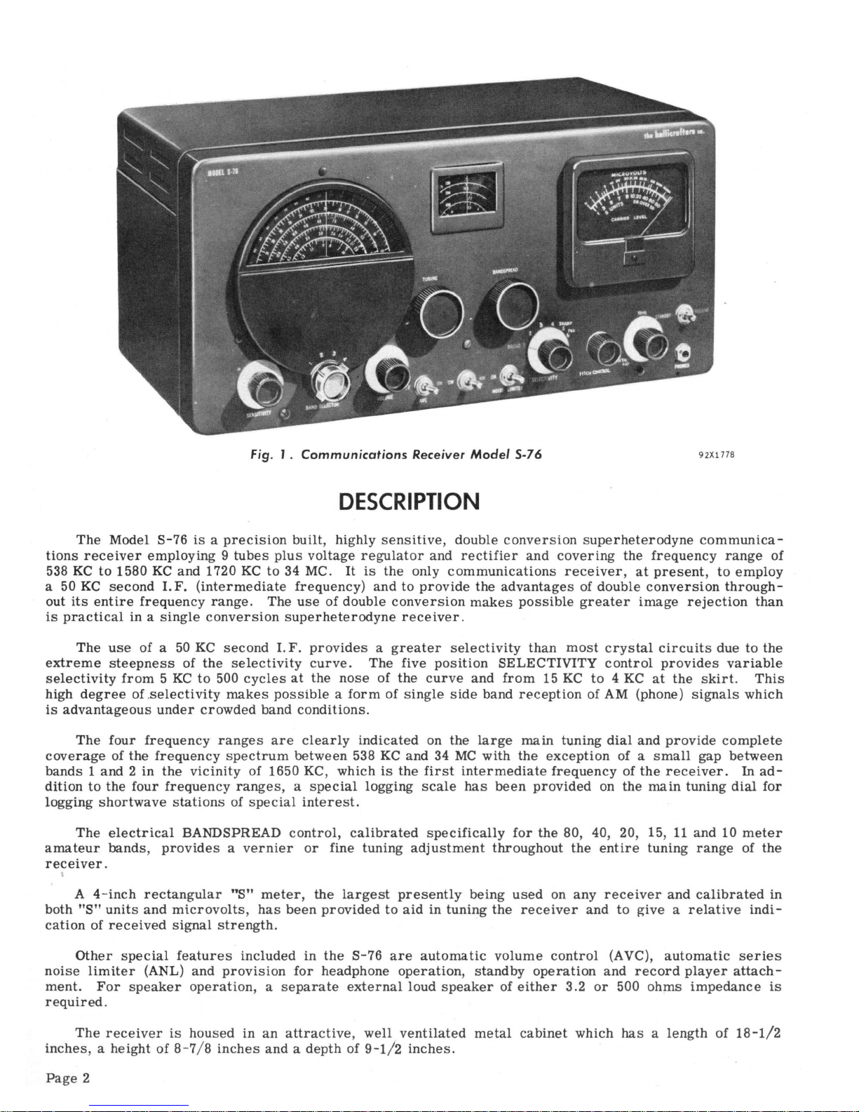
Fig.
J.
Communications
Receiver
Model
5-76
92X1778
DESCRIPTIO
N
The
Model
S-76
is a precision
built,
highly
sensitive,
double
conversion
superheterodyne
communica-
tions
receiver
employing 9 tubes
plus
voltage
regulator
and
rectifier
and
covering
the
frequency
range
of
538
KC
to
1580
KC
and
1720
KC
to
34 MC.
It
is
the
only
communications
receiver, at
present,
to
employ
a 50
KC
second
I.F.
(intermediate
frequency)
and
to
provide
the
advantages
of
double
conversion
through-
out
its
entire
frequency
range.
The
use
of
double
conversion
makes
possible
greater
image
rejection
than
is
practical
in a single
conversion
superheterodyne
receiver.
The
use
of a
50
KC
second
I.F.
provides a greater
selectivity
than
most
crystal
circuits
due
to
the
extreme
steepness
of
the
selectivity
curve.
The
five
position
SELECTIVITY
control
provides
variable
selectivity
from 5 KC
to
500
cycles
at
the
nose
of
the
curve
and
from
15
KC
to 4 KC
at
the
skirt.
This
high
degree
of .
selectivity
makes
possible a form
of
single
side
band
reception
of AM (phone)
signals
which
is
advantageous
under
crowded
band
conditions.
The
four
frequency
ranges
are
clearly
indicated
on the
large
main
tuning
dial
and
provide
complete
coverage
of
the
frequency
spectrum
between
538
KC
and
34
MC
with
the
exception
of a
small
gap
between
bands 1 and 2 in
the
vicinity
of 1650 KC,
which
is
the
first
intermediate
frequency
of
the
receiver.
In
ad-
dition
to
the
four
frequency
ranges, a special
logging
scale
has
been
provided
on
the
main
tuning
dial
for
logging
shortwave
stations
of
special
interest.
The
electrical
BANDSPREAD
control,
calibrated
specifically
for
the
80, 40, 20, 15,
11
and
10
meter
amateur
bands,
provides a vernier
or
fine
tuning
adjustment
throughout
the
entire
tuning
range
of
the
receiver
.
A
4-inch
rectangular
"S"
meter,
the
largest
presently
being
used
on
any
receiver
and
calibrated
in
both
"s"
units
and
mi.crovolts, has
been
provided
to
aid in
tuning
the
receiver
and
to
give a relative
indi-
cation
of
received
signal
strength.
Other
special
features
included
in
the
S-76
are
automatic
volume
control
(A
VC),
automatic
series
noise
limi.ter
(ANL)
and
provision
for
headphone
operation, standby
operation
and
record
player
attach-
ment.
For
speaker
operation
, a
separate
external
loud
speaker
of
either
3.2
or
500
ohms impedance
is
required.
The
receiver
is
housed
in
an
attracti
ve,
well
ventilated
metal
cabinet
which
has a length
of
18-1/2
inches
, a
height
of
8-7/ 8
inches
and a depth
of
9-1/2
inches.
Page
2
The 8-76
normally
operates
from
a 105-125 volt 50-60
cycle
alternating
current
(AC)
power
source.
The 8-76U, a
universal
model of the 8-76,
permits
operation
from
25-60
cycle
AC
sources
at
voltages
ranging
from
115 to 250
volts.
Both models have
provision
for
operation
from
an
external
DC
power
source.
The
power
consumption of
each
model
is
77
watts.
IMPORTANT
Your
careful
attention
is
especially
invited
to
the
installation
and
operating
instructions.
They have
been
provided
to
insure
the
satisfaction
you have a
right
to
expect
from a Hallicrafters
"Precision
Built"
product.
Your
receiver
has
an
unusually high
degree
of
sensitivity
necessary
to
receive
weak
and
distant
stations.
Careless
operation
of a high
sensitivity
receiver
may
result
in
excess
noise
or
background
hiss.
These
undesirable
effects
can
be held
to a minimum
by
careful
adjustment
of
the
sensitivity,
tuning and
tone
controls
as
well
as
the
proper
selection
and
arrangement
of the antenna.
INSTALLATION
INSTRUCTIONS
UNPACKING - Check
all
shipping
tags
and
labels
for
instructions
before
removing
or
destroying
them.
LOCATION - The
receiver
is
equipped with
rubber
mounting
feet
for
table
top
or
shelf
mounting. When
locating
the
receiver,
avoid
excessively
warm
locations
and
recessed
installations
which
prevent
proper
air
circulation.
The
separate
loud
speaker
should not
be
placed
on the top of the
cabinet
but should be
located
as
far
from
the
receiver
as
is
practical.
A.C.
POWER
CORO
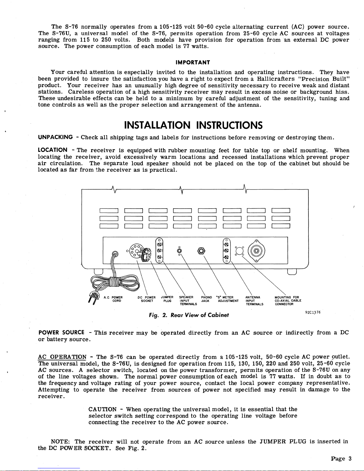
Fig. 2. Rear
View
of
Cabinet
MOUNTING
FOR
CO-AXIAL
CABLE
CONNECTOR
nC1376
POy,tER
SOURCE
-
This
receiver
may
be
operated
directly
from
an
AC
source
or
indirectly
from a DC
or
battery
source.
AC
OPERATION - The 8-76
can
be
operated
directly
from
a 105-125 volt, 50-60
cycle
AC
power !>utlet.
The
universal
model, the 8-76U,
is
designed for
operation
from
115, 130, 150, 220 and 250 volt, 25-60
cycle
AC
sources.
A
selector
switch,
located
on the
power
transformer,
permits
operation
of the S-76U on
any
of
the line
voltages
shown. The
normal
power consumption
of
each
model
is
77
watts.
If
in doubt
as
to
the
frequency
and voltage
rating
of
your
power
source,
contact
the
local
power
company
representative.
Attempting
to
operate
the
receiver
from
sources
of
power
not
specified
may
result
in
damage
to the
receiver.
CAUTION - When
operating
the
universal
model,
it
is
essential
that
the
selector
switch
setting
correspond
to
the
operating
line voltage
before
connecting the
receiver
to
the
AC
power
source.
NOTE: The
receiver
will
not
operate
from
an
AC
source
unless
the
JUMPER
PLUG
is
inserted
in
the
DC
POWER SOCKET. 8ee Fig. 2.
P'd.ge
3
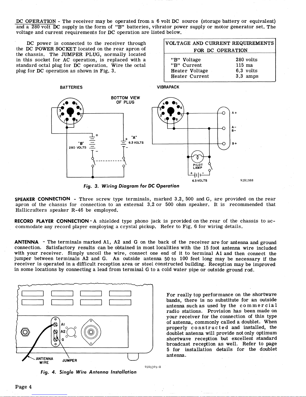
DC
OPERATION -
The
receiver
maybe
operated
from
a 6
volt
DC
source
(storage
battery
or
equivalent)
and a
280 volt
DC
supply
in
the
form
of
"B"
batteries,
vibrator
power supply
or
motor
generator
set.
The
voltage and
current
requirements
for
DC
operation
are
listed
below.
DC
power
is
connected to the
receiver
through
the
DC
POWER SOCKET
located
on the
rear
apron
of
the
chassis.
The
JUMPER PLUG,
normally
located
in
this
socket
for
AC
operation,
is
replaced
with a
standard
octal
plug
for
DC
operation.
Wire
the
octal
plug
for
DC
operation
as
shown
in
Fig.
3.
VOLTAGE AND CURRENT REQUffiEMENTS
FOR
DC
OPERATION
"B"
Voltage
"B"
Current
Heater
Voltage
Heater
Current
280
volts
115
ma
6.3
volts
3.3
amps
BATTERIES
VIBRAPACK
"8'
280
VOLTS
+
BOTTOM
VIEW
OF
PLUG
+
"Aft
-=-
6.3
YOLTS
Fig.
3. Wiring Diagram for
DC
Operation
PILOT
LAMP
+II~
6.3YOLTS
A+
A-
B-
B+
9281388
SPEAKER
CONNECTION -
Three
screw
type
terminals,
marked
3.2,
500 and G,
are
provided
on
the
rear
apron
of the chaSSiS
for
connection
to
an
external
3.2
or
500 ohm
speaker.
It
is
recommended
that
Hallicrafters
speaker
R-46
be employed.
RECORD
PLAYER
CONNECTION - A
shielded
type phono
jack
is
provided
on
the
rear
of the
chassis
to
ac-
commodate
any
record
player
employing a
crystal
.pickup.
Refer
to
Fig. 6 for
wiring
details.
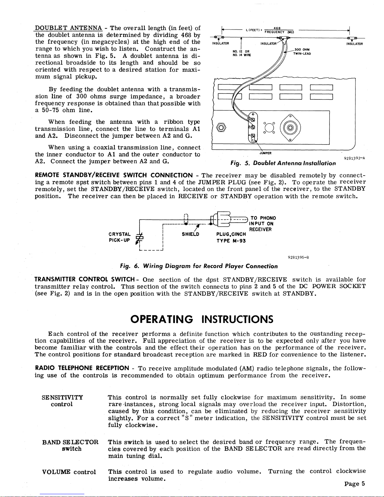
ANTENNA - The
terminals
marked
A1,
A2
and G on
the
back
of
the
receiver
are
for
antenna and ground
connection.
Satisfactory
results
can
be
obtained
in
most
localities
with
the
15
foot antenna
wire
included
with
your
receiver.
Simply uncoil the
wire,
connect one end of
it
to
terminal
A1
and then connect
the
jumper
between
terminals
A2
and
G.
An
outside
antenna
50
to
100
feet
long may
be
necessary
if
the
receiver
is
operated
in
a difficult
reception
area
or
steel
constructed
building. Reception
may
be
improved
in
some
locations
by connecting a
lead
from
terminal G to
a cold
water
pipe
or
outside ground
rod.
Page
4
ANTENNA
WIRE
Fig.
4. Single Wire
Antenna
Installation
9281391-8
For
really
top
performance
on
the
shortwave
bands,
there
is
no
substitute
for
an
outside
antenna
such
as
used
by
the
com
mer
cia
I
radio
stations.
Provision
has
been
made
on
your
receiver
for
the connection
of
this
type
of antenna, commonly
called
a doublet. When
proper
ly
con
s t r u c
ted
and
installed,
the
doublet
antenna
will
provide
not only optimum
shortwave
reception
but
excellent
standard
broadcast
reception
as
well.
Refer
to
page
5
for
installation
details
for
the doublet
antenna.
DOUBLET
ANTENNA -
The
overall
length
(in
feet)
of
the
doublet
antenna
is
determined
by
dividing
468 by
the
frequency
(in
megacycles)
at
the
high
end
of
the
range
to
which
you
wish
to
listen.
Construct
the
an-
tenna
as
shown
in
Fig.
5. A
doublet
antenna
is
di-
rectional
broadside
to
its
length
and
should
be
so
oriented
with
respect
to a desired
station
for
maxi-
mum
signal
pickup.
By
feeding
the
doublet
antenna
with a transmis-
sion
line
of 300
ohms
surge
impedance, a broader
frequency
response
is
obtained
than
that
possible
with
a
50-75
ohm
line.
When
feeding·
the
antenna
with a ribbon
type
transmission
line,
connect
the
line
to
terminals
Al
and
A2.
Disconnect
the
jumper
between
A2
and
G.
When
using a coaxial
transmission
line,
connect
the
inner
conductor
to
Al
and
the
outer
conductor
to
A2.
Connect
the
jumper
between
A2
.and G.
/4-r---
LlFEETI'
FREQ~~:CY
(MCI
NO.
12
OR
NO.
14
WIRE
JUMPER
300
OHM
TWIN-LEAD
Fig.
5. Doublet
Antenna
Installation
INSULAlOR
REMOTE
STANDBY/RECEIVE SWITCH CONNECTION -
The
receiver
may
be
disabled
remotely
by
connect-
ing a
remote
spst
switch
between
pins 1 and
4 of
the
JUMPER
PLUG
(see
Fig.
2).
To
operate
the
receiver
remotely,
set
the
STANDBY/RECEIVE
switch,
located
on the
front
panel
of the
receiver,
to
the STANDBY
position.
The
receiver
can
then
be
placed
in
RECEIVE
or
STANDBY
operation
with
the
remote
switch.
CRYSTAL
PICK-UP
n
,....------++----+1-
---
-----
TO
PHONO
r-------~""-,--
~~~~~~RN
I SHIELD
I
I
I 1
I-
____
...l
PLUG,CINCH
TYPE
N-93
Fig.
6. Wiring Diagram for Record Player Connection
9261395-6
TRANSMITTER CONTROL SWITCH - One
section
of
the
dpst
STANDBY/RECEIVE
switch
is
available
for
transmitter
relay
control.
Thls
section
of
the
switch
connects
to
pins 2 and
5 of the
DC
POWER SOCKET
(see
Fig.
2)
and
is
in
the
open
position
with
the
STANDBY/RECEIVE
switch
at
STANDBY.
OPERA
liNG
INSTRUCTIONS
Each
control
of
the
receiver
performs a definite
function
which
contributes
to
the
oustanding
recep-
tion
capabilities
of
the
receiver.
Full
appreciation
of
the
receiver
is
to
be
expected
only
after
you have
become
familiar
with
the
controls
and
the
effect
their
operation
has
on
the
performance
of the
receiver.
The
control
positions
for
standard
broadcast
reception
are
marked
in
RED
for
convenience
to
the
listener.
RADIO
TELEPHONE
RECEPTION
-
To
receive
amplitude
modulated
(AM)
radio
telephone
signals,
the
follow-
ing
use
of
the
controls
is
recommended
to
obtain
optimum
performance
from
the
receiver.
SENSITIVITY
control
BAND
SELECTOR
switch
VOLUME
control
This
control
is
normally
set
fully
clockwise
for
maximum
sensitivity.
In
some
rare
'instances,
strong
local
signals
may
overload
the
receiver
input.
Distortion,
caused
by
this
condition,
can
be
eliminated
by
reducing
the
receiver
sensitivity
slightly.
For a correct
liS
II
meter
indication,
the
SENSITIVITY
control
must
be
set
fully
clockwise.
This
switch
is
used
to
select
the
desired
band
or
frequency
range.
The
frequen-
cies
covered
by
each
position
of the BAND
SELECTOR
are
read
directly
from
the
main
tuning
dial.
This
control
is
used
to
regulate
audio
volume.
Turning
the
control
clockwise
increases
volume.
Page
5
RADIO
TELEPHONE
RECEPTION
(Cont.)
AVC
switch
This
switch
should be
set
to the
ON
position
to
place
the
automatic
volume
control
(AVC)
circuit
in
operation
•.
The
AVC
circuit
provides a constant
audio output
level
over
large
variations
in Signal
strength
at
the antenna.
TUNING
control
This
control
should be
set
for
the
desired
station
frequency
after
setting
the
BAND
SELECTOR
for
the
desired
band.
Frequencies
on
all
bands
are
shown
in
megacycles.
IMPORT ANT - The
main
tuning
dial
calibration
is
correct
only when the BAND-
SPREAD
control
is
fully
clockwise.
CW / AM
switch
This
switch
should be
set
at
AM.
BANDS
PRE
AD
control
This
control,
calibrate<;t
specifically
for
the
80,40,20,15,
11
and
10
meter
amateur
bands,
is
a fine tuning
adjustment
provided
for
electrically
spreading
out
the
con-
gested
amateur
and
shortwave
bands.
AMATEUR
BAND
RECEPTION -
To
use the BANDSPREAD
control
on the
amateur
bands,
set
the BANDSPREAD
control
fully clockwise, index the TUNING
control
for
the high end of any of the
amateur
bands
as
indicated by the white dots on the
main
tuning
dial
and then tune
through
the band using the BANDSPREAD
control.
The
station
frequency
is
read
directly
from
the bands
pre
ad
dial.
SHORTWAVE RECEPTION -
To
tune in shortwave
stations
with the BANDSPREAP
,
control,
set
the BANDSPREAD
control
fully
clockwise,
position
the TUNING
control
for
the high
frequency
end
of the
range
of
frequencies
to
be
covered
and
then
tune
through the
frequency
range
with
the BANDSPREAD
control.
Note
that
the
station
frequency
CANNOT be·
read
directly
from
either
the
main
tuning
or
bandspread
dials.
However,
it
is
possible
to
log shortwave
stations
by
recording
the
settings
of both the
bandspread
dial
and the
main
tuning logging
scale.
See
inside
of back
cover
for the sh.ortwave
station
log.
NOISE
LIMITER
This
switch
is
normally
set
at
OFF.
Set
the
switch
at
ON
when
severe
electrical
switch
disturbances
interfere
with
reception.
SELECTIVITY
This
switch
is
normally
set
at
BROAD
for
maximum
fidelity.
Positions
2, 3, 4 and
switch
5 provide
increasing
steps
of
selectivity.
Note
that
as
the
receiver
is
made
more
selective
(clockwise
rotation
of the
SE
LECTIVITY
control),
the background noise
and
interference
from
nearby
stations
is
reduced.
The
setting
of the SELECTIVITY
control
is
generally
best
determined
by
receiving
conditions, the SHARP position
providing
maximum
selectivity.
A
slight
readjustment
of the BANDSPREAD
con-
trol
may
be
necessary
when changing the position of the SELECTIVITY
control.
SINGLE SIDE
BAND
RECEPTION -
The
method of bandwidth expansion
used
in
this
receiver
makes
possible a form
of
single
side
band
reception.
As the
sel-
ectivity
is
changed
from
the SHARP to the
BROAD
position
the bandwidth of the
receiver
not only
increases
but
also
shifts
in
reference
to
the 50
KC
intermediate
frequency,
permitting
only one
side
band to be
accepted.
For
single
side
band
reception,
set
the
SELECTMTY
control
to SHARP, tune
in
the
AM
Signal and then
set
the SELECTIVITY
control
to
BROAD. The
"S"
meter
level
will
decrease
with
an
increase
in bandwidth and if the
receiver
is
not
retuned,
only one
side
band
will
be
accepted.
PITCH CONTROL
This
control
is
not
used
for
RADIO TELEPHONE RECEPTION.
TONE
control
Page
6
This
control
turns
the
receiver
on and off and
also
attenuates
the high audio
fre-
quencies
to.
the
extent
required
by the
various
receiving
conditions.
To
turn
the
receiver
on,
turn
the TONE
control
clockwise
beyond
the
point
of
switch
action.
For
maximum
high
frequency
audio
response,
turn
the TONE
control
fully
clockwise.
 Loading...