

Page 1
j
instqllqtion
qnd
-J
.:;:.::,:,-j
.-
=
.-
operdfing
for
model
rqdio
f
eGefve
f
-
insfrucfions
5-4ol
tflAY,
Jh^s..,hn.l
i,q
I
1946
rs
I"tH,{.l
94-1454
EO.
t6, U. s. A.
60
Page 2
I
I
:
l
I
i
-l
.
\l
i
i
i
I
I
I
I
r
I
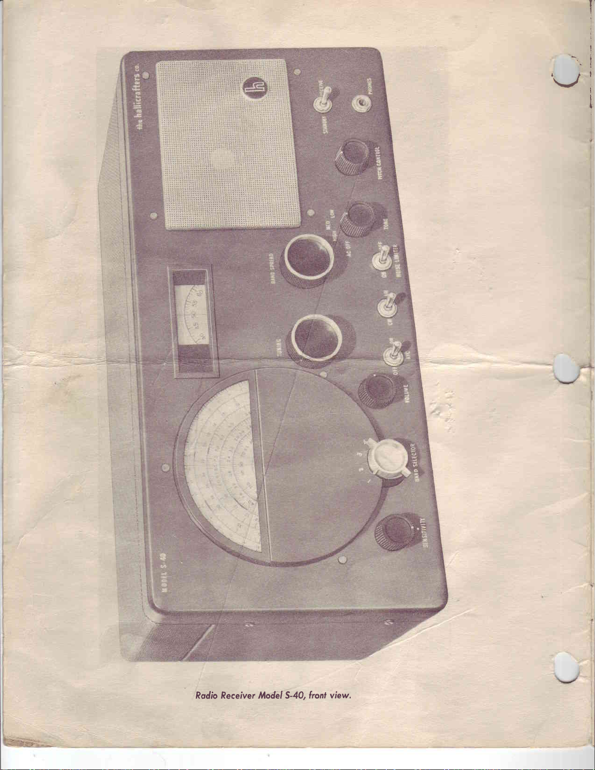
Recerver Modiil S-40, front
Rodio
view,
Page 3
J
INSTALTATION
AND
INSTRUCTIONS
FOR
RADIO
RECEIVER MODEL
OPERATING
S.4O
GENERAL.-YouI receiver is
pable
fiequency
(megacycles). A
indicated
as
venient
tuning dial scale
radio
of
reception such as automatic
the optional
code
enthusiast.
The
quires
prong plug which is attached
On
power such as a 6-volt storage battery
Another socket
ternal
receiving
of
ranges
on the attractively illuminated
foreign
which
the
station
reference
stations. A band spread
is
signals
receiver is designed to operate from a 105 to
watts of
75
rear
"S"
tuning
standard
continuous
with
bandswitch is provided for selecting the four ranges
locations
radio
for
is
also located a logging scale which
described later
use
of the
a headset. A beat
of
intelligible, this feature being especially
power for
receiver chassis
is
provided on
meter which
a table
broadcast
are also clearly
amateurs
dial is provided
in
these
noise limiter and volume control.
operation.
to
is available upon
model,
and foreign
coverage
(hams)
instructions.
frequency
six foot line cord extending
the
is
provided
and
the rear of the
nine tube superheterodyne radio
domestic short wave stations over
or
provided from
main
tuning dial scale. The
indicated
and also the short wave listener. On
for fine
Connection
"8"
on the
is used as a reference when
tuning of short wave stations,
Special
oscillator
125-volt, a-c,
a socket for
batteries
receiver chassis
request from a Hallicrafter distributor.
features are provided to
(b.f.o) is
useful to the
to the power source
or vibrapack.
kc (kilocycles) to 43
54O
of
amateur
main
tuning dial
Provision is made for
provided for
radio
6O cycle source
5Of
from the rear of
connecting to a d-c source of
for
the
receiver ca-
reception which
bands
scale as a con-
amateur
is made by the two
connection of
as well
the
logging
the
improve
rendering
and code
and
the cabinet.
an ex-
four
mc
are
main
use
re-
The complete
receiver
is 9 inches high by
28 pounds.
maximum output of
The
distortion.
MECHANICAL
ventilated
well
mechanical strength.
provides
ments. Mixer and oscillator
the
near
for
control
ELECTRICAL
receiver circuits
up at
is selected by
a means of gaining
holes provided
the front of the cabinet
tuning and operating
markings are
the anrenna
DESCRIPTION.-The
aerodized sheet
DESCRIPTION.-The block
in a simple
and fed to the
a resonant
the
The full length aerodized
for
this
in red. This
circuit and
18[
receiver at
metal
access to all of
adjustments
purpose
provide access to the
are located on the
manner which
antenna coil of
the
model S-40
cabinet
may
under the
is
aid the
to
fed to the
is described
inches
spqaker
minimize electrical
to
top
the tubes,
made
be
notice card.
front of
novice
diagram,
the
mixer-oscillator
wide by
is one watt with
radio receiver
cover,
Jiz.l lamps and
from the
Three small
oscillator
receiver. Notice that some
the
in
operating
Figure
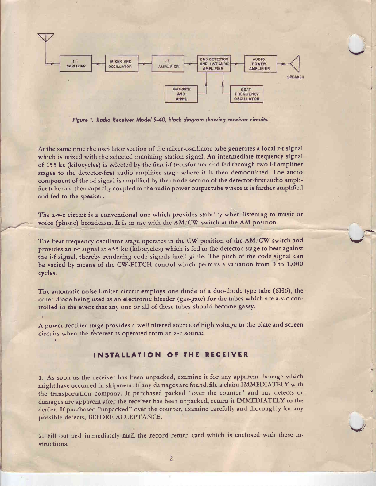
follows: radio signals
as
r-f
stage
11 inches deep
less than ten
is
housed
interference and
mounted
bottom
padder
2, iilustrates the
where the
on
i-f transformer
of the cabinet
holes
adjustments.
receiver.
the
desired station
tube.
in
an
a piano
on
All controls
function of the
and weighs
Percent
attractive,
provide
type hinge,
adjust-
through
the bottom
of the
picked
are
signal
Page 4
V
Figure l.
At
the same time
which
of
stages
component
fier tube and then capacity
and fed to the speaker.
Thb a-v-c circuit
voice (phone) broadcasts.
The
provides ant-f. signal
the
be
cycles.
The automatic
other
trolled
is mixed
kc (kilocycles) is
455
to the detector-first
of the
frequency oscillator
beat
i-f
signal,
varied
diode being
means
by
in the event that
Rodio Receiver Model *4O,
the
oscillator
with the selected
selected by
i-f
signal
coupled to the audio
is a conventional one
at455
thereby
noise limiter
rendering code signals
the C\(-PITCH
of
used as
an electronic
any one or
block
mixer-oscillator tube generates
section of
incoming station signal.
audio
is amplified by the
It
amplifier
is in
use with
stage operates
kc (kilocycles) which
circuit
the
first i-f
the
stage
which
the
in
control
employs one
bleeder
all of these
diogrom
transformer
where
triode section
power output
provides stability
AM/C\/ switch
the CV
is fed to the
intelligible. The
which
diode of
(gas-gate)
tubes
showing
An intermediate
and fed through
it is then
of the
tube where
position
permits
a duo-diode
for the tubes which
should become
receiver circuils.
a local r-f signal
frequency signal
two i-f amplifier
demodulated.
detector-first audio
is
it
further
listening to
when
position.
AM
at the
AM/C\/ switch
the
of
detector stage
pitch of the
a variation
gassy.
to beat
code signal
from 0 to
type tube
The
amplified
music or
against
(6H6)' the
a-v-c con-
are
audio
ampli-
and
can
1'000
-sF
V
power
A
circuits
rectifier
when
stage
the r'eceiver
INSTALTATION
As soon as the
L.
might have occurred
the transportation
damages
dealer.
possible
Z.
structions.
are apparent
Ifpurchased
defects,
Eill our and
receiver
BEFORE
immediately
provides a well
is operated
has
in
shipment.
company.
the
after
"unpacked"
ACCEPTANCE.
mail the
filtered
from an a-c
OF
unpacked,
been
If any
purchased
If
receiver has been
over
damages are
packed
the counter, examind
record
high voltage to
source
return card which
of
source.
THE
examine
found,
"oyer
unpacked,
RECEIVER
it for any apParent
a claim
file
the counter"
return
carefully
plate and
the
damage wb.ich
IMMEDIATELY
any
and
it IMMEDIATELY
and thoroughly
is enclosed with
screen
with
defects or
to the
for any
in'
these
a
\J,
Page 5

,J
This
I
3.
piece
receiver
of
furniture.
is
equipped
Do
not mount
with rubber
this radio
mounting
on a radiator
feet for mounting
or any
area subject
on a table
to heat
or other
hu-
or
midity.
4.
An
external
On the rear
A2 and
directed.
An
help
external
G. Select one
external
to improve
ground, always
antenna
apron
ground connection
reception
should
receiver
of the
of the antenna
especially
connect
be connected
chassis is
systems
is
not
on the higher
it
to the terminal marked
to the receiver
located
described
essential to
as follows:
the antenna
below and
receiver,
this
frequencies.
"G"
connector
connect it
in
but
If it is
on the
antenna
strip,
marked
to
the strip as
some locations
desired
to use
terminal
A1,
will
an
strip.
\J
A. Single
jumper
75
results.
of antenna
installation
of antenna is recommended
the receiving
where
quired
I
range
wires should
nals ,{,1
with
used, connect
to terminal
to terminal
between
(t) To determine
of the doublet antenna in
to
between the
feet
(including
Erect
B. Doublet
maximum
of frequencies.
grounded
(a) Determine
which
tilire
Antenna,-When
antenna
lead-in)
the antenna
works well where
is
over a relatively
and Az.If
A1,
A2 and
terminal
you
practical.
not
Antenna.-This
conditions
connected
be
outer conductor is
the inner
the outer
the proper length
the
wish to listen.
are poor
sensitivity is
The lead-in
a concentric
connect a
A2
and G.
frequency range
terminal A2 and
to terminal AL.
as high
narrow
to termi.
conductor
conductor
feet:
and free
the
signal to noise ratio is
Refer
to Fig.
type
where
or
re-
line
jumper
using
3.
a
single wire
G.
Use
fft4
from
surrounding
Figure
Then
connect
gauge copper
relatively
'TNGLE
wrRE ANTENNA
JUMPER
2,
Single Wire
DOUBLET
USING
antenna installation,
a
single wire
objects
high
Antenna
ANTENNA
TWISTED
PAIR
wire
TO GROUI{D
LEAD-IN
heavier for
or
possible.
as
and a more
rNsrALLATroN
OONIIECTIOiI
Installation,
INSTALLATION
connect a
of about
This
elaborate
50
best
type
to
J
(b) Divide 468
(in
megacycles)
quency end ofthe
(z) To prepare
stallation:
(a) Measure
determined in
sert an
of the lead-in
wave sections at the
shown
insulator
\frap and solder the two
@)
in
Figure 4.
by
of the
range
the antenna for
the wire to the length
(b) above
step
at
that
to each of the quarter-
the frequency
high
fre-
you
selected.
in-
in-
and
point.
wires
insulator
as
Figure
3, Doublel
TO
Anlenno
GROUND
COiII{EOTION
Instollation.
Page 6

mind
in
Keep
so orientated
For reference to other types of antennae
A.R.R.L.
radio amateur
that this
if maximum pick-up ftom a given
Handbook,
"ham"
type of antenna
section
equipment.
on antennas. This
is directional
broadside
direction is desired.
refer
to the
book
latest edition
can be
its length and should be
to
from
Radio
most
of the
procured
Amateur's
V
dealers of
D-C
OPERATION.-This
storage battery,
pack.
The
will
voltage will
as
(1)
the socket
(2) Use
"8"
(3) Connect
on the
(4) Use
battery
about
be
follows:
Remove the octal
ffrc
supply connections
"jumper
rtt2
connections
(5) Connect
to pin
one
(6)
Solder
continuity.
trical
and
filament
70
run approximately 10
the rear of the chassis.
at
gauge
one of these
plqg."
gauge
one of these
rt7.
connections securely
the
CAUTION-Check
receiver may
27o-volts
current
milliamperes. The
"jumper
d-c supply
drain in
plrg" used for a-c operation
be operated
in
the
case
this
6-volt battery
amperes. The receiver
insulated copper wire leads
and-
wire leads to
insulated copper wire
pin
leads
ff3
and-
leads to either
wire
as to provide good
so
wiring carefully
the
before
form
will be
for the
and one
for
the
pin
rtt
connecting
a 6-volt d-c source,
from
dry batteries
of
about
5
using a vibrator
drain
is connected
from
26o-vok
to pin
or
fs
"A"
and
6-volt
elec-
uP to
or vibrator
ampefes, while
to
B-
270V. D-C
B+
rts
Figvre 4,
for
the battery
generally
type
"8"
the
supply
d-c supply
the
PfN VfEW
Wiring diagram
power plug.
d-c
suppli.
power
current
"B"
for
6V.
D-C
ezazte
a
\l
I
I
PRE-OPERATIONAL
recommended
(f)
See
location
(2) Check
in place.
(3)
Check
Remember
before
that the
each tube.
of
pilot
the
all external
an improvised
that
tubes are securely
CHECK-The
turning on the
lamps
located
connections.
power
seated
behind
See
installation
OPERAIION
following checkup
for the first time.
in their sockets.
dial escutcheons
the
that they
gives
OF
are secure
improvised results.
THE RECEIVER
a newly
on
Refer to Figure 7
installed
and see that
make poriiiu"
and
receiver is
for the
Proper
they are securely
contact.
t
I
I
,l
receiver from
THE CONTROLS.-Scanning
EXPLANATION
left to
l
NOTE.-Some
for the convenience of
setting
Reference to
right,
the controls
OF
control
the
of the conrol
the listener
mosr used
Figure 5 will
markings and
markings are
who
for the
help the
listener
an
explanation
in RED. This
is not familiar with
reception of standard
in
becoming
across
the front of
of each
familiar
is as
added
is an
radio terminology
broadcast
with
the
follows:
feature
stations.
the use of
incorporated
as
the
^n aid
conuols.
in
v
a
Page 7

,f,).
)-J
I
I
J-.
,,
I
\J
1. SENSITIVITY
the control
"S"
meter
the control is
2. BAND
the listener.
main
the
sufficient
VOLUME
3.
level
the
4, A.Y,C.
reasonable
over
the sensitivity
ON to use the tuning meter,
Main
5.
reception
scale
instructions.
6. AM/C\/
quency necessary
AM position.
BAND
7.
control for fine
instructions.
clockwise increases
switch
SELECTOR
tuning
overlap to provide
volume most
of
switch.-This
TUNING
which
the dial may
on
switch.-This switch turns
SPREAD tuning.-This control is
control.-This
which connects
advanced maximum
switch.-This
The frequencies
Position
dial.
control.-This
pleasing
switch, when
variations in
of the
receiver
control.-This
is read
for making
tuning
on the
be
of short wave stations,
used for
control regulates
the sensitivity
the tuning meter,
clockwise.
switch selects the desired
covered
fit
continuous
control
signal strength at
when this
when one
main
code signals intelligible.
by each
(in red)
coverage
sets
to the
set at
is
control
tuning dial located
logging purposes
of the receiver.
band switch position
is
the
over the
the audio level at
listener.
"ON,"
circuit
on a local
is in
used.
tunes the
used
the use of which
the sensitivity
Ganged to this control is
when one
standard
provides
the antenna, i.e. it
operation. This
receiver
which
oscillator
For
in
conjunction
is
used, into
band or
broadcast
overall tuning range
the speaker
a constant audio
to the
to the left
ordinary
of
is
described
used
with the main TUNING
is
of the
to produce
receiver,
the circuit
frequency range
read
are
band. Each range has
is
and
automatically controls
switch must
desired frequency
the
control. The outer
later on
reception
explained
Turning
directly from
receiver.,
of the
to
be
output
be set at
in
the beat fre-
it is
set
in
later
thi
when
for
set for
level
these
in
the
these
of
NCISE LIMITER
8.
peaks
where
noise
9.
speaker
types
to the
frequencies
LOS/
position
frequencies
I
ing
I
J
ceiver while leaving
condition for
in a
putting
generated
reception
but will
TONE
or
response
of
receiver
(a) LO\Xz-The
.
(b)
position providing a response
(c) HIGH-The
10. PITCH
to amateur
11.
STANDBY-RECEIVE
standby condition
the
do a
control.-This control
headset
is
only.
MED.-The
is
preferred for
providing
control.-This
or
instant
receiver
switch.-This switch cuts in a circuit
electrical disturbances,
by
would normally
job
good
and also includes
available are-LOrW, MED.
disconnected.
and high frequencies
bass
bass and high frequencies are attenuated
voice communications when
bass and
response
good
control is
commercial
switch.-This
thq tube heaters
use. This
when transmitting.
in an inoperative
be
of limiting it
adjusts the tone qualities of the audible
medium
code
stations.
switch
thereby providing
impossible.
to
a switch which turns
more
for
frequencies are attenuated in
for high audio frequency response.
used to vary the pitch
switch
at operating temperature,
is
used
For the
condition
This feature
a reasonable level.
HIGH. In
and
are attenuated to provide a response
than the
disconnects
the radio amateur
by
general
ready
which clips the noise voltage
intelligible
will not
A-C power
the
the A-C
somewhat less
ordinary voice frequencies. This
the signal to noise ratio
of the code signal
d-c
the
thus
"ham"
listener it provides a means
instant
for
use.
reception in
totally
position
OFF
favor of the high audio
voltage from the re-
leaving
to
remove
signal for either
ON or OFF. The
than for the
will
when
receiver in
the
put
the
cases
the
the power
for voice
permit.
listen-
receiver
of
Page 8

6'
s
a
c
o
lrt
E
o
a-
6'
-
o
o
o
=
o
F
?'l
I
6'
{
o
{
t'
c
o
o
o
o
I
d
2.r,
:o
3
OD
=o
o@
!D{
o
o
8r-
laq
'9'g
@
-o
9€
=e
r8
^o
36
g;r
irg
tc'2
99
iEfi
'96'
;e
=:
u
T
I
=rl
;$
#
r
-=+\
t
ir,
.!
;
V
tf
@€
@;
OJ
of
.o
gEc
da3
oc:
9.o
=o@
o_-;
'
oii
oo
9-9
a
-
I
I
I
5
c
3;ag
dr?1
B.;E
ii
i:!i
5 -'-
o *i
e69
i
o
\-/
Page 9

BAND
use
the
frequency
tuning
BAND
"O."
at
station
You
control.
in
band spread
LISTENER.-To
control,
with
calibrations
SELECTOR
slightly
is
I
f.
:'{
a
J
t
FOR
ing
dial pointer
with
10
meter
dial
pointer
spread
BAND
ranges'
range
on the
FOR
the
band
dial pointer
and
then
IMPORTANT.-The
BAND
"HAM."-To
THE
the BAND
band. Set the
at
dial
pointer
SPREAD
although
of tuning
broadcast
THE
SHORT
spread tuning
counterclockwise
tune in
SPREAD
at
the high
SPREAD
mc (megacycles),
3o
tuning
the higher
on th_e
band.
\/AVE
the
dial pointer
OWNER'S
PREVENTIVE
the tuning
fully
without
caused
receiver.
/-t'
I
j
their
by dirty
Check
sockets.
MAINTENANCE.-Keep
capacitors. Dust
bending the
condenser
the switch
and
capacitor
wipers,
contacts
SPREAD
band spread
end
of the range
control.
at
the high
can now
The
frequency
set the
the BAND
on the main
ser at
listen
preceding
is the range
tuning
band spread
past
"o."
TTAINTENANCE
the various
dirt
should
plates
faulty
and
volume
controls
TUNING
dial,
set the
Exampler-Assume
position
end
of the 1o meter
in
on the L0
example
dial
scale. Band
in
tune
the frequency
SPREAD
be
in
short wave
tuning
blown out
the
slightest.
controls,
and make
to be
4 (t5.7
holds
of tuning,
dial
pointer
control.
dial
parts
dial
covered
meter
spread
of
the
scale are
of the receiver
with dry
Noisy
switches
sure
pointer
you
to 43
band, and
rrue for
the nariower
broadcast radio
at
station
that
"O,"
at
and
tune in
wish
to listen
mc),
set main TUNING
then
band
by tuning
any
of the*frequency
tuning is
"O",
set the main
you wish to
only
correct
clean,
air
or
brushed
reception
and tubes,
all
tubes
set main
the
set the
will
nor necessary
stations with
may
eic. in
are always
tun-
stations
in
on the
band
with
the
be the
tuning
tune in
when the
especially
o^ot .or"-
be also
the
in
Figvre
6, Rodio
REPLACING
fully
and
determine
type
sockets
25O
ma,,
glass bead above
PERIODIC
should
or shows
these
performance
I
A
from
ing
not
stages.
complete
any
for
this
TUBES AND
'replace
the location
"blue
require realignment
signs
one
with the correct
of each
illuminate
to
bead"
ADJUSTMENTS.-This
Alignment
is
obtained
service
of our distributors
bulletin,
G.E,
the
glass stem inside
of loss in
bulletin is
ask
Receiver
DIAL
tube. The receiver
the two
or
#47
until it
sensitivity,
should
only by intelligent
for
not
available
or
SERVICE
ltlodel
LAMPS.-\Ufhen
type. Refer
dial scales. Replace
equivalent.
the envelope
receiver
needs new
frequency
off
be attempted
for
dealers
BULLETIN
940, view
to the
The color
has
alignment.
use in
servicing
or by contacting
showing
replacing
top
employs
these
code referred
of
the
been carefully
tubes in
calibration
inexperienced
by
for Radio
{t,
fube locofions.
tubes,
of the receiver
lamp.
the r-f
this receiver
the factory
check
two
dial
lamps
with similar
to is
aligned
and mixer-oscillaror
requires
or
persons
dnd
direct.
Recliver
the
tube type
chassis,
types,
thi
at
the factory
service
can be obtained
Model
Fig.
with
b-ayonet
6/8 volt,
color
stages
work
as maximum
Vhen
inquir-
S-40.
care-
to
z,
of the
and
on
Page 10

'r;
.r
V
meter is
The
is mounted at the
trol
instructions
tuning
The
request
the external
in the
metering
screen
from the company.
above
reception, the
current
PILOT
Figvre 7. Tuning
mounted in an attractive
front of the case
are supplied with
"S
first
METER"
the
meter
second
and
merer
connection of
illustration and should be
of
LIGHT
meler SM-4O snd schemolic
meter.
the
is not supplied with
Provision has been
"S"
meter. A
measures a voltage drop
i-f amplifier tubes.
case to
for meter zero
plugged
match
made on the
five
prong plug
into socket
wiring
receiver
the
adjustment.
receiver,
the
rear apron
is
wired to the meter
provided for
across a
diogrom,
cabinet.
Installation
but
resistor,
A zero adiust con-
can be
of the
this purpose. When
and adiustment
purchased
receiver for
indicated
as
i.e.
a change
on
\./
in
Page 11

t-
vl
6SG7
R4
Iq
cdT
J_
:
r
I
I
I
I
I
6SA7
rt3
d
v3
6SK7
--v
I
RESISTANOE
VALUES
ARE lN DEOIMAL
OAPAOfTOR
----7
NUI{ERALS
ANTEHNAIMIXEF
AT
(T1
TO
LUoA
SHOWN
FOR
OPERATION
NOTE.
VALUES ARE
ARE IN
VALUES ARE
/
/
AT
T12 ) IDENTI
ON PTCTOnIAL
POSITION
IN
NO.I
IAND
lN OHMS,MICA
MMF. PAPER
DENOTESMEOHANIOALGANGM
BANDSWIIOH
CAPACITOR
IVALENTS
EOT
IN MFD.
(Sl
ANDOSCILLATOR
oORRESPONDING
FY
VIEIS.
CAPAoITOR
VALUES
ELEOTROLYTIC
OF MFQr
LETTERS
AND
)
TRANSFORM€Rs
TERMINAL
BANDSWITCH
S-I
,s.
ilETER
=
SOCKET
aTERl,
sHoYitl
s4B
swtToH
IN POSITION
t.
9
30
3l
,r
21
7i
23
32
@*
Dg
FOR
WAFER
aF
-:t-
s-rE
(END
NEARESTOIIASSS
REAR APRON)
REPRESENTS
TRANSFORMERS
T.I TO
T.I2
Page 12

v4
6SK?
'5
6S07
v6
F6.G
6
G-
'13
+'
l"c,
I BLACK
Jisg
'T*
J-
.Lcqo
Tro-iro ./
R,n
47,do
SwrrcH
t-A.c oFF
(3W4t
ronE
Rzc
dJ.
,6
*--*aao-----,
J,'
:/
iidd
,t
/
2-HIGH
3-il€0rut
*-LOU
FORITIERS
T-l TO T.l2
T0
HEAIER9.
"8,
METER
SOCKET
Ttg
7
sroRTtNG PLUG PL2
IN
MUST BE
FOR
SOCKET SO.
A.O. OPERATION.
Page 13

J
I
{Dsusntu
>J-
I
TJ
The HallicraJter's
Jactared
and agrees
changeJor
installation,
deliaered
utbolesaler
all
oJ
close=s tn ozr
haoe been
oilr oran,
Jarnisbed
altered oatside of our
tbereo/
ased thereutith not oJ our
be remedied or excbanged
saler uithoat
plied
any otber liability
by it to be
any
by the outner to t s or to oar ailborized radio
transportation cbarges
grlgi2su)urcbase-r
salzto
utarranty does not extend to any
Tbis
Ary
sablected
irnproper
by
has been remooed, deJaced
part
Tltis
utananty is in
and no representatioe or
Companl lpanafits eacb nera radio
to rernedy
/rom
oJ a
frce
any
part
of an! trnit
ase and seruice discloses sacb defect,
utbom
jadgment
as, nor extend to
cbarge
tbat
to miszse,
installation, or to
factory,
anit
approt
to the
connection uitb tbe
in
defectiue material and utorAtnansbip
/rom
szcb defect or toJarnisb a neu
of
mana/actare ubicb ander normal
its
parcbased,
prepaid
oun mana/actare,
liea of all otber utananties
intact,
utitbin ninety
and
Prooided
thrs deJectioe,
it is
neglect, accident, incorcect uiring not
nor to
ed
for
by
the ailhorized
outner,
person
of
ilse
zrits utlticb baoe
cdses ubere the serial number
or cbanged, nor to
remedT or exchange bereander utill
is
proaided
our examination, uitb
/or
days
tbat sucb ex4mlaalion di1-_
radio
oar
in aiolation
radio dealer
aathorized to assilnte
sale oJ otr radio
product
part
Jrom
prodacts
of
instractions
been
repaired or
expressed
mant-
in ex-
the
unit h
dealer
or
the date
utbich
accessories
utbole-
or
or im-
ils
Jor
prodacts,
_-
 Loading...