

Page 1
'Bllicraliers
OPERATING
AND
COMMUNICATIONS
SERVICE
TRANSMITTER
MODEL HT-46
INSTRUCTIONS
Page 2
~ARRA.NTY
"The Hallicrafter's Company warrants each new radio product manufactured
and agrees to remedy any
change
mal installation, use and service discloses
unit
saler, from whom purchased,
examination, with
days from the date of sale to original purchaser and provided that
such examination discloses in our ;udgment that it is thus defective.
This warranty does not extend
have been sub;ected to misuse, neglect, accident, incorrect wiring not
our own, improper installation,
furnished
altered outside of our factory
nor to accessories used therewith not of our own manufacture.
Any
be remedied
saler without charge to the owner.
This warranty is in lieu of all other warranties expressed or implied
and
other liability in connection with the sale of our radio products:'
by
it to be
free.
from defective material and workmanship
for
any part of any unit of its manufacture which under nor-
is
delivered by the owner to our authorized radio dealer, whole-
by
us, nor extended to units which have been repaired or
where the serial number thereof has been removed, defaced
part of a unit approved
or
exchanged by the authorized radio dealer or whole-
no representative
such defect
all
transportation charges prepaid within ninety
or
or
person
or
to furnish a new part in ex-
such
defect, provided the
or,
authorized service center, intact,
to
any
of
our radio products which
or to use in violation of instructions
authorized service center, nor to cases
for
remedy or exchange hereunder will
is
authorized to assume
for
or changed,
for
us any
Page 3
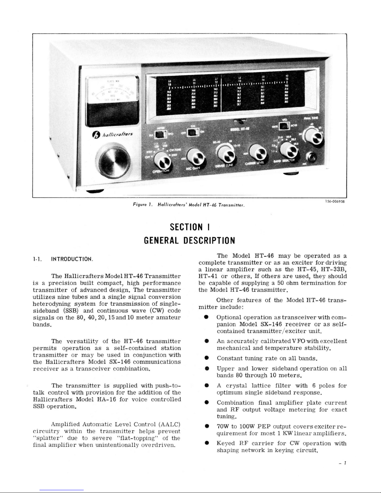
Figure
1.
Hol/icrafters'
Model HT-46
Transmitter
.
156-006 958
SECTION
I
GENERAL
DESCRIPTION
1-1. INTRODUCTION.
The
Hallicrafters
Model
HT-46
Transmitter
is a precision
built
compact,
high
performance
transmitter
of
advanced
design.
The
transmitter
utilizes
nine
tubes
and a single
signal
conversion
heterodyning
system
for
transmission
of
single-
sideband
(88B)
and
continuous
wave
(CW)
code
signals
on
the
80, 40,
20,15
and
10
meter
amateur
bands.
The
versatility of the
HT-46
transmitter
permits
operation
as a self-contained
station
transmitter
or may
be
used
in conjunction
with
the
Hallicrafters
Model 8X-146
communications
receiv
er
as a tran
s ce
iver combination.
The
transmitter
is
supplied
with
push-t
o-
talk
control
with
provision
for
the
addition
of the
Hallicrafters
Model
HA-16
for
voice controlled
88B
operation.
Amplified
Auto
matic
Level Contro
l (AALC )
c
ircuitry within the tra
nsmitt
er he
lps preve
nt
"splatter "
due
to se ve
re
"flat-toppin
g" of the
final
amplifi
e r when
unintentionall
y ove
rdri ven.
The
Model
HT-46
may
be
operated
as
a
complete
transmitter
or
as
an
exciter
for
driving
a
linear
amplifier
such
as
the
HT-45,
HT-33B,
HT-41
or
others.
If
others
are
used,
they should
be
capable
of
supplying
a 50
ohm
termination
for
the
Model
HT-46
transmitter.
Other features
of the
Model
HT-46
trans-
mitter
include
:
•
Optional
operation
as
transceiver
with com-
panion
Model
8X-146
receiver
or
as se
lf-
c
ontained
transmitt
er / e
xciter
unit
.
• An
accurately calibrated
VFD
with exce
llent
me
chanic
al
and
temperature
stabilit
y.
•
Constant
tuning rat
e on
all
bands.
• Upper
and
lower
sideband
operati
on on
all
bands
80
throu
gh 10
meters.
• A cr y
stal
latti
ce
filt
er
with 6 poles
for
o
ptimum
sing
le
sideband
r e
sponse.
•
Combinati
on
final
amplifier
plat
e c
urrent
and
RF output
volta
ge
meterin
g for exact
tunin
g.
• 70W to
lOOW
PEP output cover
s exciter r e-
quir
eme
nt
for mo
st 1 KW
linear a
mplifi
er s.
• Keyed
RF car r ier for
CW
oper a
tion
with
s
hapin
g ne two
rk
in keying ci
r c
uit.
- 1
Page 4
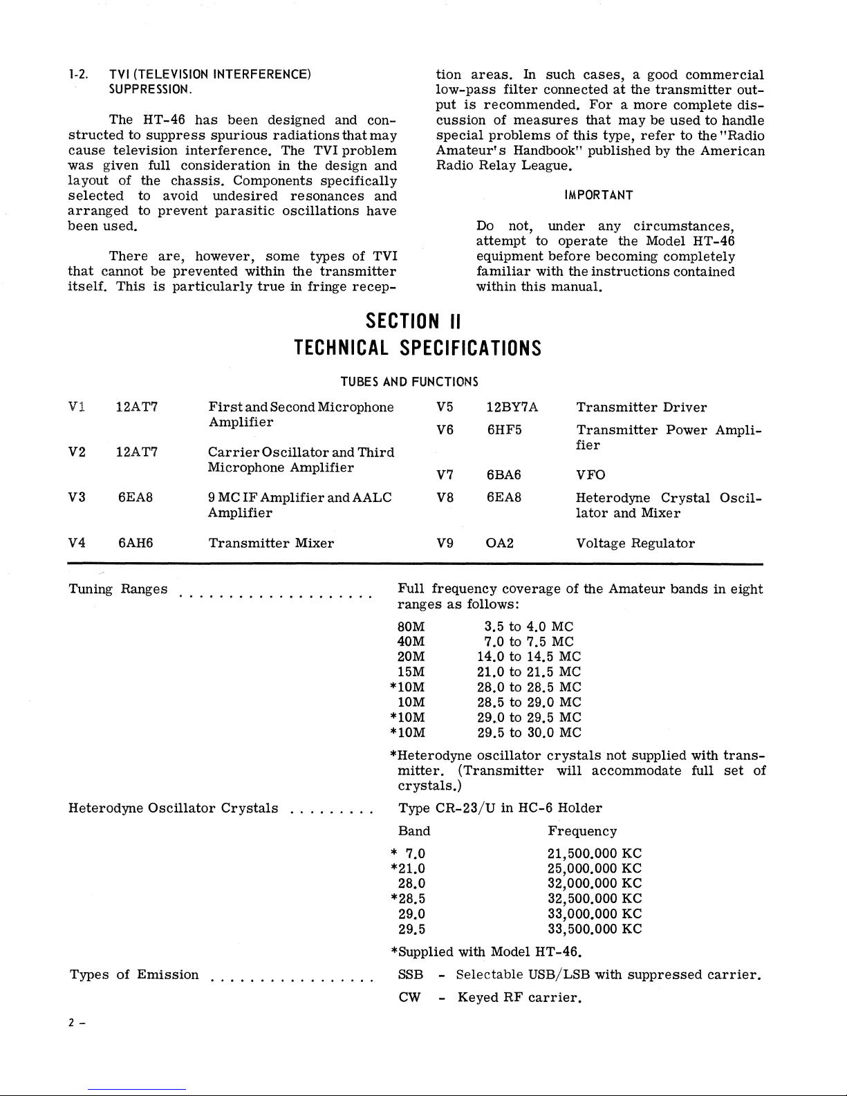
1-2.
TVI
SUPPRESSION.
The
structed
cause
was
layout
selected
arranged
been
that
itself.
television
given
used.
There
cannot
(TELEVISION
HT-46
to
suppress
full
of
the
to
avoid
to
prevent
are,
be
This
is
INTERFERENCE)
has
been
spurious
interference.
consideration
chassis.
prevented
particularly
Components
undesired
parasitic
however,
designed
radiations
in
some
within
true
and
that
The
TVI
problem
the
design
specifically
resonances
oscillations
types
the
transmitter
in
fringe
con-
may
and
and
have
of
TVI
recep-
tion
areas.
low-pass
put
is
recommended.
cussion
special
Amateur's
Radio
problems
Relay
Do not,
attempt
equipment
familiar
within
In
filter
of
measures
Handbook"
League.
this
such
cases,
connected
of
this
IMPORTANT
under
to
operate
before
with
the
manual.
a good
at
the
For a more
that
may
be
type,
refer
published
any
circumstances,
the
Model
becoming
instructions
commercial
transmitter
complete
used
to
to the
by the
American
HT-46
completely
contained
outdis-
handle
"Radio
Vl 12AT7
V2
V3 6EAB 9
V4
Tuning
Heterodyne
Types
12AT7
6AH6
Ranges
Oscillator
of
Emission
...................
First
and
Second
Amplifier
Carrier
Microphone
MC
Amplifier
Transmitter
.............
Oscillator
IF
Amplifier
Crystals
SECTION
TECHNICAL
TUBES
Microphone
and
Amplifier
and
Mixer
.........
AND
Third
AALC
.
*10M
*10M
*10M
*Heterodyne
* 7.0
*21.0
*28.5
*Supplied with Model
. .
..
II
SPECIFICATIONS
FUNCTIONS
V5
V6
V7
V8
V9
Full
frequency
ranges
80M
40M
20M
15M
10M
mitter.
crystals.)
Type
CR-23/U
Band
28.0
29.0
29.5
SSB -
CW
-
12BY7A
6HF5
6BA6 VFO
6EA8
OA2
coverage
as
follows:
3.5 to 4.0
7.0
to 7.5
14.0 to 14.5
21.0 to 21.5
28.0
to 28.5
28.5 to 29.0
29,0 to 29.5
29.5 to 30.0
oscillator
(Transmitter
in
HC-6
Selectable
Keyed
RF
MC
MC
crystals
Frequency
21,500.000 KC
25,000.000 KC
32,000.000 KC
32,500.000 KC
33,000.000 KC
33,500.000 KC
HT-46.
USB/LSB with
carrier.
Transmitter
Transmitter
fier
Heterodyne
lator
Voltage
of
the
MC
MC
MC
MC
MC
MC
will
accommodate
Holder
and
Mixer
Regulator
Amateur
not
supplied
suppressed
Driver
Power
Crystal
bands
with
full
Ampli-
Oscil-
in
eight
transset
carrier.
of
2 -
Page 5
Frequency
Control
Type of Sideband
Transmission
Dial
Calibration
Calibration
Frequency
Output
Power
Impedance
Input . .
Microphone
Audio
Response
Distortion
Control
Accuracy.
Stability
...
Input
Overall
Products
Unwanted Sideband
Carrier
Power
Station
VOX Unit
SX-146
Transceive
Number
Dimensions
Net
Shipping
Accessories
Suppression
Supply
Control
Input.
of
Weight
Weight
Requirements
Receptacle
. . . . . . . . . . . . . . . . . . . . . .
Cable
Tubes
Overall
. . . . . . . . . . . . . . . . . . . .
.......
Generation
.....
. . . .
. . . .
..
.
.....
.
......
. . . . . . . . . .
Rejection
Capability
Outlet
. . . . . . . . . . . . .
................
Impedance
..........
........
.
..
.
...........
.
....
........
..
.
.
.
Self-contained
SX-146
Solid
receiver.
state
(Nominal
SSB -
CW
- Manual.
5 KC
increments,500
Less
than
indexing
Less
than
minute
warm-up,
VFO
modulator
BW
= 2.1 KC).
Push-to-talk
outlet
cessory.
circuitry.
(Model HA-16.)
Rear
inch two
at
control
one
at
3.5
500
conductor
outlet.
pointer
MC.
cycles
and
or
transceive
with
at
microphone
VOX
key
KC tuning
width
drift
less
operation
9 MC, 6 pole
or
through
control
jack
accepts
phone plug.
is
Key
range.
error
in
first
than
across
hour,
100
cycles
with
crystal
control
optional
standard
circuit
the
dial
after
per
Model
filter
ac-
1/4-
also
after
fifteen
hour
thereafter.
Fixed,
accepts
SSB - 175
CW
0.005V RMS
accepts
500 CPS (Max.) to 2200
26 DB (Min.)
50 DB (Min.)
50
..
117V AC,
Rear
.
Amphenol
contacts,
control,
Rear
.
type
power
Rear
(Supplied.)
operation
75
8
5-7/8 x 13-1/8
26
28 pounds
VOX
attachment
voice
Model
three
pound. Shipping
50
ohms.
RCA type phono plug. (Supplied.)
Watts
- 150
Watts
into
standard
below
below
DB (Min.)
below
50/60
chassis
type
speaker
etc.
chaSSis
71-6S
and
chassis
mounted
plug. (Supplied with
control
receptacle
Provides
with Model SX-146.
ohms.
Use
Amphenol
plus 1 voltage
pounds.
(Approximately)
Control
to
controlled
HT-46
tubes
through
and
Rear
PEP
Maximum
Maximum
high
impedance
1/4-inch
CPS
PEP
PEP
output
PEP
cycles,
mounted
86-PM11
muting,
six-pin
for
VOX
inter-connection
regulator
x 11
inches
Unit
Model HA-16.
rear
of
Model
operation.
single
sensitive
Weight-1-l/2
chassis
mounted
load.
three
conductor
(Min.)
at
6 DB.
reference.
at
800 to 2200 CPS input.
output.
350
Watts.
eleven-pin
plug. (Supplied.)
receiver
socket
muting,
accepts
jumper
Adaptor,
accepts
cable
and
NO.
Model HA-16.
RCA
21-597
15
diodes.
(HWD).
Designed
HT-46
(VOX)
plug-in
VOX
Power
connector.
relay.
cabinet
Net
pounds
receptacle
Panel
connector
phone plug.
socket
accepts
Provides
relay
transmitter
Amphenol
wire.)
type
Provides
phono plug.
for
transceive
or
equivalent.
for
to
is
derived
quick
provide
from
Contains
Weight -3/4
(approximately).
Fuse
. . . . . . . . . . . . . . . . . . . . . . . . . .
.. 3 amperes,
slow
blow, 3
AG
type.
- 3
Page 6
SECTION
III
INSTALLATION
WARNING
LETHAL
HIGH
VOLTA
GE
IS
PRESENT
WITHIN
THIS
EQUIPMENT.
BE
CARE-
FUL
WHEN
INSTALLING THE
UNIT
OR
PERFORMING
CHECKS
OR
ADJUS T-
MENTS
INSIDE
THE
CABINET.
3-1.
UNPACKING
.
Ca
refully remove
the
equipment
from it
s
carton and
packing material
and
examine
it
for
possible dama
ge
which may
have occurred
in
transit
. Should any sign
of dama
ge
be
apparent
,
immediately
fil
e a
claim
with the c
arrier sta
tin
g
the extent
of the
damage.
Che
ck
all
shipping lab
els
and
tags
for
special
instructions be
for e r emoving
or
destroying
them.
3-
2.
LO
CATION.
The transmitt
er
may be
installed
in any
l
ocati
on
that
will
permit
free
circulation
of
air
thr
ough
the
ventilation
openin
gs
in
the
cab
ine
t.
Do
not
place
any
obj
ect
on
top
of
the
cabinet
in
o
S
X-146
INJEC
T
J3
t t
•
GROUND
AN1ENNA
J4
J5
a
manner
that
will
obs
tru
ct
normal
ventilation
.
Avoid
exce
ssiv
ely
warm locations
such
as thos
e
near
radiators
and
heating vents.
3
-3.
PO
WER
SOURCE
.
Th
e Mo
del
HT-46
Transmitter
is design
ed
to
operate
from
a 105/ 125V 50/ 60 cycle
AC
pow
er
Sour
ce.
Nominal line voltage
for
testing
and mea-
surements
is
117V
.
The outlet
should
be
capabl
e
of
handlin
g a 350 w
att load
with
good reg
ulati
on.
IMPORTAN
T
If
in
doubt
about
your
power sour
ce,
co
nta
ct your loc
al
pow
er
company
prior
to
inserting the
power
cord into an
y
po
wer outl
et.
Plugging the power
co r d
into the wr
ong
source
of
power can
cause exte
nsive dama
ge
to the
trans-
mitter.
Set the
OPERATION c
ontr
ol
at OFF (fUll
co
unt
er clockwis
e)
and
make
all
installation
con
-
nection
s b
efo
r e connecting the transmitter
to a
source
of
power
.
•
PI, J6
R33
MODEL
HT-46
105/125
VOLTS
50160
CPS
@\
POWER
CONSUIolPTION
350
WATTS
,
_'!/J
BIA
S
KEY
f
AMP
ADJ
J2
FI
156-0070
28
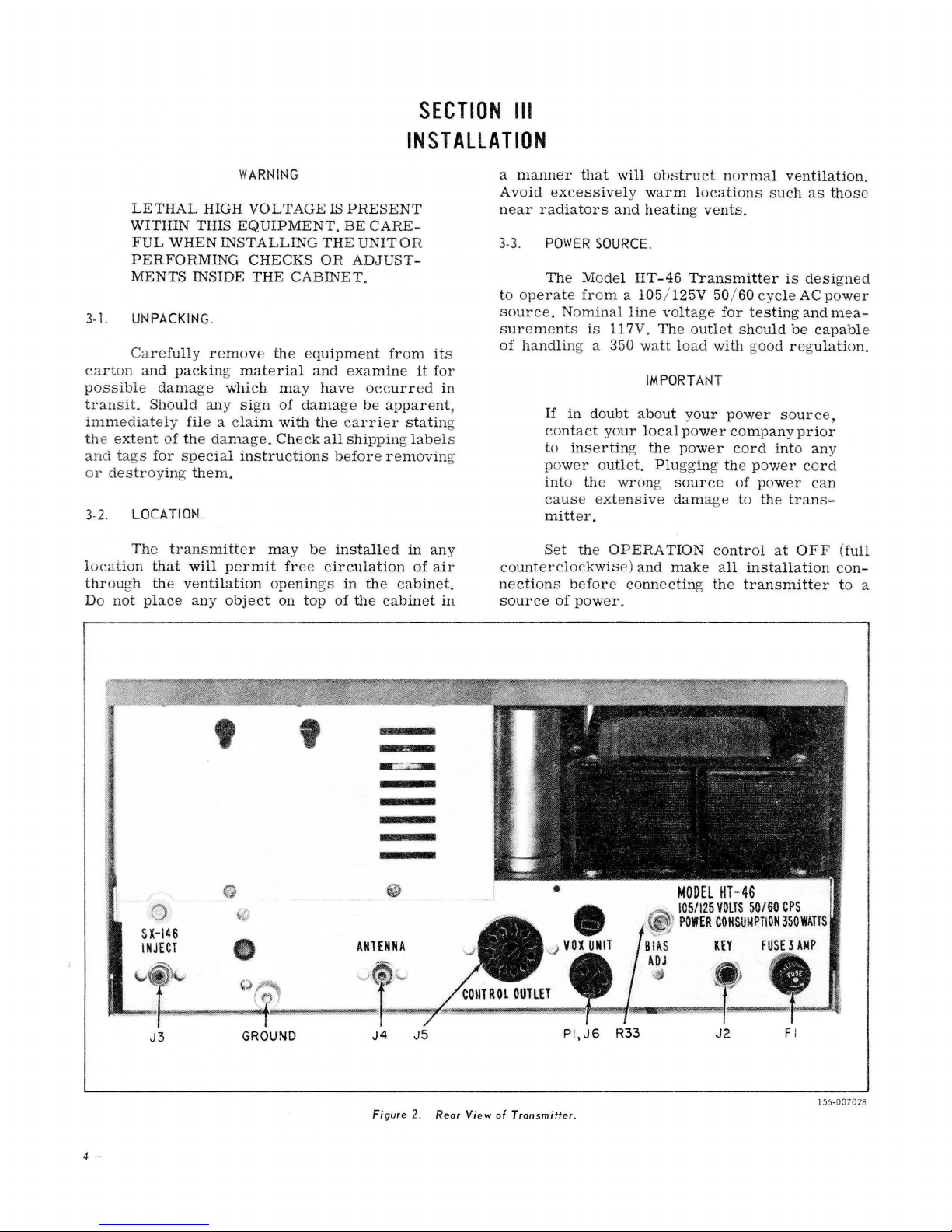
Figure
2.
Rear
View
of
Transmitter
.
4 -
Page 7
SPKR
I
,~
HUH
,~
SX
GND
,~
I
146
GND
EXTOSC@
INPUT
.8
SLAVE
6~\~~~
®
ANT
®<
AHPHENDL
lY
PE
21-591
lh
TRANSCEIVE
CABLE
1-"
HT-46
,----5
q
SX-4~
®
ii
ANTENN
'\.7
L------J-------+-------+----t----
L-------+-------+---------t
3-4.
ANTENNA_
The
Model
terminate
into a
line. A non-reactive
results,
modated
results.
antennas
give
however
by
Any of
using
excellent
For
antennas,
book"
by
the
refer
or
the"
American
Some
be
provided
code
The
ANTENNA
chassis
nector.
for
feed
apron
Use
line
changeover
details.
3-5.
GROUNDS.
All
station
gether
with
connected
ground.
provided
for
this
An
on
purpose.
HT-46
50
a VSWR
the
50
results.
further
to
ARRL
Radio
form
of
requirements.
mates
RG-58/U
to a linear
relay,
heavy
to a cold
external
the
Model
EARIH
WATER
GROUND
Figure
Transmitter
ohm
unbalanced
load
is
of
transmitter
the
popular
g,q.~
transmission
information
the
"Radio
Antenna
Relay
IMPORTANT
lightning
which
will
connector
with
an
co-axial
Refer
to
eqUipment
copper
water
chassis
HT
-46
OR
COLD
PIPE
RG58/U-50~
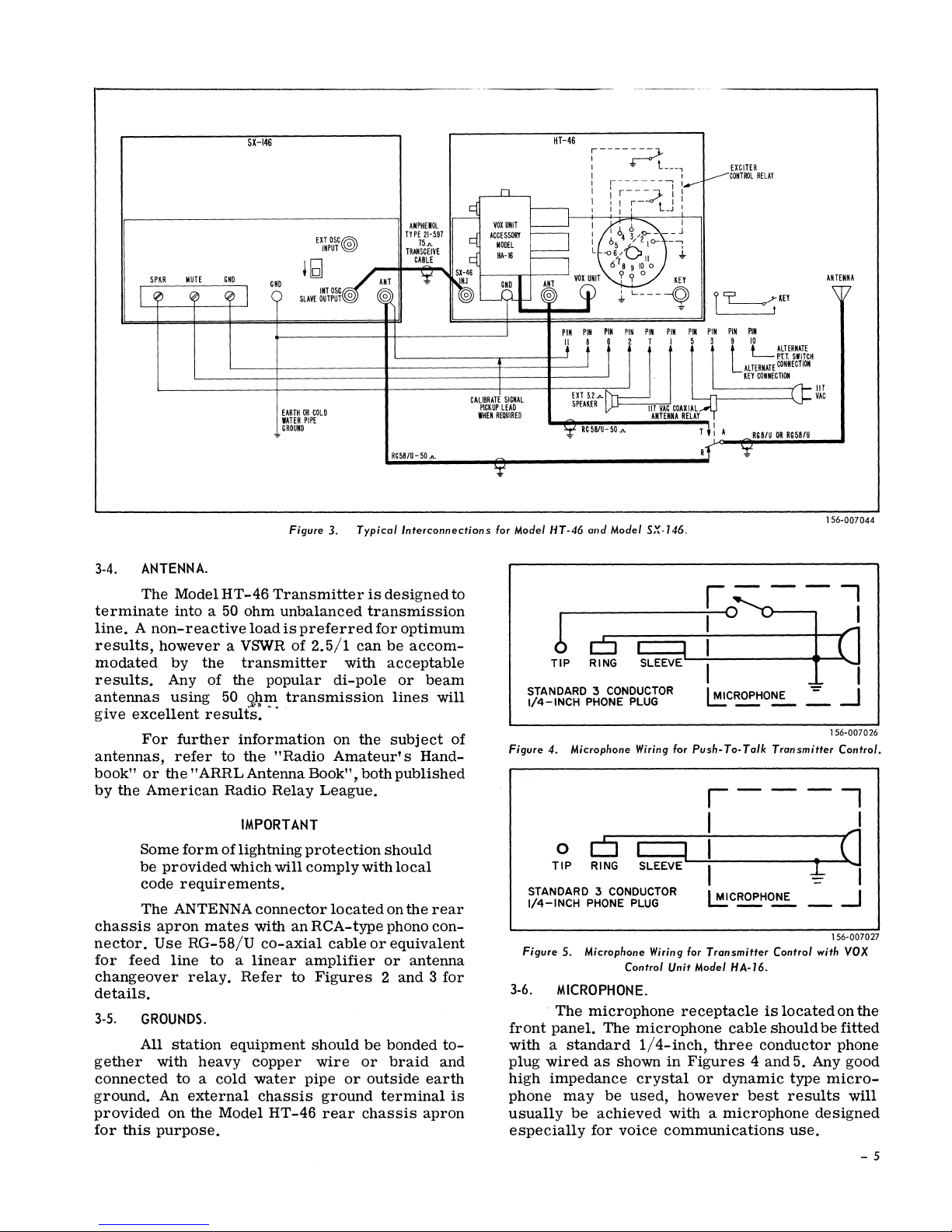
3.
Typical
Interconnections
is
designed
transmission
preferred
2.5/1
for
can
with
di-pole
optimum
be
accom-
acceptable
or
lines
on
the
subject
Amateur's
Book" ,
both
Hand-
published
League.
protection
comply
located
RCA-type
cable
amplifier
should
with
local
on
phono
or
equivalent
or
the
antenna
Figures 2 and 3 for
should
wire
pipe
or
or
ground
rear
chassis
be
bonded
braid
outside
terminal
apron
to
beam
will
of
rear
con-
to-
and
earth
is
I
i
----1I--.:;;;-;:--
CALIBRATE
SIGNAL
PICKUP
LEAD
WHEN
REQUIRED
for Model
STANDARD
1/4-INCH
Figure
STANDARD
1/4-INCH
Figure
3-6.
front
with a standard
plug
high
phone
usually
especially
~
~ ~ ~ ~ ~ ~ m ~ ~
I, t UJ6
E
Xl
SPEAKER
1-"
HT-46
32
~
RG58/U-5DA
and
Model
2-,lJ
I 5 1
III
VAC
ANTENNA
SX·146.
COAXiAl
b
TIP
RING
:3
PHONE
4. Microphone Wiring for
0
c5
TIP
RING SLEEVE
PHONE
5.
Microphone
MICROPHONE.
The
microphone
panel.
wired
as
impedance
may
be
for
SLEEVE
CONDUCTOR
PLUG
:3
CONDUCTOR
PLUG
Control
The
microphone
1/4-inch,
shown
crystal
be
used,
achieved
voice
Wiring for
Unit
in
with a microphone
communications
3
LLk.~~J:l~~H
KEY
CONNECTION
(J:
DR
RS58tU
--
III
VAC
156-007044
-,
I
Bf
RElAY
d:
A
RS8tU
~-"'I"":;';:';;';";;;;";~---
RT
1-"
1-
1°
--
I
I
~C~O~
Push-
To-
Talk
Transmitter
--
--
I
I
I
I
I
l.!:!!C~~
Transmitter
Model
receptacle
three
Figures 4 and
or
dynamic
however
HA-16.
cable
conductor
best
Control
is
located
should
results
--
~
5. Any good
type
use.
I
':'
-l
156-007026
Control.
I
I
G
I
-
-1
156·007027
with
VOX
on
the
be
fitted
phone
micro-
will
designed
- 5
Page 8
The
microphone
may
also
be
microphones
mute
the
microphone
pressed,
Ie
ss
3-7.
hence
the
microphone
KEY.
The
station
transmitter
rear
chassis
Refer
two
so
which
TROL
with
tion
to
Figure
conductor
that
the
is
at
OUTLET
Pins
NO.1
to
the
keyer.
used
fitted
VOX
at
the
apron
3. The
1/4-inch
key
base
ground
maybe
or
circuit
with
VOX
with
push-to-talk
element
operation
switch
keyer
may
closed
or
at
the
key
phone plug.
connects
potential.
used
NO. 8 used
shown
control,
in
Figure
however
switches
until
the
switch
is
not
possible
is
altered
be
circuit
accordingly.
connected
key
jack
CONTROL OUTLET.
jack
accepts a standard
Wire
the
to
the
plug
sleeve
Pin
NO.
90f
the CON-
to
key
the
transmitter
for
ground
connec-
some
also
un-
to
the
at
the
plug
is
4
Receiver
Keying
PTT
SPDT
Calibrate
3-10.
FUSE.
Specifications: 3 amperes,
muting:
circuit:
control
relay
signal
Pins
Pins
circuit:
contacts:
coupling:
NO.6
NO.9
Pins
Pins
AND
and
NO.
NO.3,
NO.
Pin
slow
and
NO.8
NO.8
10
and
5
NO. 11
blOW, 3 AG
NO.
NO.4
8
type.
3-11.
ACCESSORY
INSTALLATION.
When
the
the
keyer
tune
circuit
up
in
the CW-TUNE
TION contro1.
When the
OUTLET,
jack
3-8.
insert a dummy
to
hold
the
SX-146
INJECT.
Transceive
able
when a
between
Model SX-146
The
INJECT
SLAVE
removing
receiver
venient
should
75-ohm
the
Model
receiver.
cable
receptacle
OUTPUT
the
receptacle.
length to
be
made up
RCA-type phono
75-ohm
(NO. 21-597)
microphone
3-9.
be
station
that
control
co-axial
CONTROL
The
required
wiring
the
following
outlet.
is
type
control
by the
Speaker
keyer
is
plugged into the KEY
must
be
position
keyer
is
wired
phone plug into the
circuit
type of
open
operation
co-axial
HT-46
is
connected
on
the
connector
82
ohm
dummy
The
cable
reach
of
plugs
cable
between
75-ohm
at
each
made
recommended.
cable
for
this
OUTLET.
outlet
circuitry
station
circuit
is
shown
facilities
muting:
Pins
NO.7 & NO.1.
jack
closed
into
for
of
the
SSB
the
or
CW
OPERA-
CONTROL
key
for
CW
operation.
is
made
avail-
cable
is
connected
transmitter
between
transmitter
on the
receiver
load
may
co-axial
end.
Small
by
Amphenol
Do
not
and
the SX-146
and
plug
be
any
the
units
cable
diameter
use
shielded
the
after
in
con-
and
with
Corp
the
the
application.
mayor
may
not
installation. A typical
in
Figure
are
available
NO.2 & NO.8
3. Note
at
the
and
1. 10
tional
coverage.
sary
(Refer
indicate
crystals
To
to
remove
to
paragraph
their
BAND
28.0
29.0
29.5
2.
VOX
Model HA-16
voice
control
mitter.
mitter
It
is
cabinet
A.
sently
on
Save
the
installed
the
rear
the
control
jumper
unit
B.
of
the
transmitter
about
1/8
inch
C. Hook
unit
into the two
wall
just
above the
notched
ground
flange between the
bolt.
D.
the
control
unit
is
now
ready
Meter
install
location.
Band
will
be
the
the top
7-2).
FREQUENCY
32,000.000
33,000.000
Crystals:
required
crystals
portion
Chassis
The
crystals
for
full
it
will
of the
markings
required
KC
KC
Three
10
be
NUMBER
019-201963
019-201965
33,500.000 KC 019-201966
Control Unit Model HA-16: The
adapter
operation
installed
as
Remove the
chassis
Loosen
unit
of
the
on the
follows:
in the
VOX
apron
plug
for
is
disconnected.
the
and
space
is
available
Model
rear
jumper
UNIT
of
it
must
ground
HT-46
of the
plug
socket
the
transmitter.
be
bolt
the
flat
to
(PI)
replaced
at
apart.
the
Tighten
Plug
unit
into the
for
Model HA-16
key
holes
ground
the
ground
the
inter-connecting
VOX
adjustment
in
bolt
flat
the
and
washers
bolt
UNIT
and
VOX
rear
insert
nut.
socket.
operation.
addi-
meter
neces-
cabinet
will
are:
PART
provide
Trans-
trans-
pre-
located
the
rear
washers
control
cabinet
the
of
the
cable
The
if
of
6 -
Page 9
SECTION
IV
4-1.
TUN
ING
The
quency
of
a
of
the
transmission
separate
operating
the
Model SX-146
this
control
mission
is
Note
to
right
for
the
calibration
logged
from
below
right
The
lowest
frequency
tuned.
4-2.
OPERATION
The OPERATION
switch
as
which
follows:
POSITION
OFF
STBY
USB/LSB
(Two
CW-TUNE
CONTROL.
tuning
control
VFO to
when the
unit.
(VFO
the
transmitter
receiver
is
disabled
controlled
that
the
two
bands
marks.
these
marks,
to
left.
BAND
SELECTOR
of
CONTROL.
controls
positions)
FUNCTIONS
is
select
transmitter
switch
as a transceiver
(VFO
and
the
by
the
frequency
whose
numbers
For
the
the
band
control
the
mode
Removes
from
Application
power
and
plate
tubes
in a stand-by
transmitter
permits
cuits
time.
In
these
transmitter
operation
band
mode
color
or
LSB
and
is
SELECTOR
ings.
This
transmitter
carrier
ing
the
operation.
position,
may
also
operation.
used
to
vary
the
desired
at
XMTR.) When
switchatRCVR)
frequency
receiver.
increases
the
remaining
frequency
setting
or
band
segment
is a six
of
transmission
FUNCTION
all
primary
the
transmitter.
places
voltages
which
are
condition. The
control
the
receiver
to
function
two pOSitions
is
for
suppressed
of
transmission.
code
indicates
for
the
so
coded
panel
position
on
only
to
transmitter
In
the
be
keyed
OF
the
frequency
is
used
of
trans-
from
appear
indicates
of
single
above
bands
increases
being
position
power
primary
both
heater
on the
biased
relay
at
placed
side-
carrier
band
in
on
the
BAND
mark-
places
the
air
permit
for
this
same
transmitter
for
OPERATING
fre-
as
with
left
the
off
cir-
this
the
in
The
USB
use
the
with
tun-
SSB
CW
4-3.
balanced
audio
range
level
tions.
4-4.
tuned
driver
The
mitter
as a transceiver
4-5.
output
transmitter
tion.
switch
level.
4-6.
rotary
crystals
shown
refer
band
4-7.
capacitor
the
calibrated
the
procedure.
4-8.
metered
idle
trol,
current
voltage
the
CONTROLS
STBY
MIC
GAIN.
This
control
modulator
amplifier
to
handle
microphone
DRIVER
The
circuits
control
CARRIER
The
The
is
BAND
The
switch
on
to the
pOSitions on
FINAL
The
P A
capacitor
METER
The
1.
plate
and
2. At RFO,
output
TUNE.
DRIVER TUNE
stages
is
output when
CARRIER
level
for
tuning
control
set
at
SELECTOR.
BAND
which
required
the
dial.
TUNE.
FINAL TUNE
that
stage
in
band
SWITCH.
METER
circuits
At
MA
current
to
indicate
on
the
across
of
the
This
position
heater
and
ceiver
sets
stage
stages.
any
high
deSigned
of
the
signal
driving
always
tuned
operating
with
the
LEVEL.
LEVEL
CW
process
also
ON to
control
SELECTOR
selects
to tune
The
color
USB/LSB
the
OPERATION
tunes
the
to
the
antenna
segments
near
resonance
switch
in
the
the
meter
when
final
40 to 300
the
the
50
transmitter.
is a second
which
and
again
circuits
the
audio
from
The
control
impedance
for
voice
control
frequency
the
final
for
as a transmitter
SX-146
control
operation
for
CW
functions
the
is
the
tuned
the
frequency
coded
coding
control
pi-network
load.
to
permit
during
selects
transmitter.
is
setting
the BIAS ADJ.
amplifier
milliampere
meter
ohm
indicates
transmission
The
stand-by
retains
supply
permits
the
voltages
the
re-
to function.
level
to the
the
microphone
has
sufficient
high
or
low
communica-
resonates
mixer
amplifier
maximum
the
and
stage.
trans-
or
receiver.
sets
the
RF
and
during
or
SSB
when
calibrate
an
eight
circuits
the
opera-
the
CAL
signal
position
and
ranges
panel
markings
for
the
two
side
control.
drives a variable
used
to couple
The
control
presetting
the
tuning
either
used
to
of
read
two
the
con-
stage
plate
range.
the
RF
line
scale
is
cali-
is
at
- 7
Page 10

brated
to
up and
4-9.
in
indicate
operating
CALIBRATE
The
carrier
when
the
ing
in
the
obtain
level
the
may
control
ON
places
in
the
standby
ceiver
4-10.
in
VFO
This
operation
percent
transmitter
signal
CAL
be
if
the
of full
maximum
the
SWITCH.
for
switch
CW
mode,
calibrate
varied
desired.
the
control
position
receive
SWITCH.
two
position
scale
RF
power
transmitter.
provides a low
frequency
is
set
the
key
signal.)
with
the
Setting
relay
to
mode
switch
when a Model SX-146
and
the
output
spotting
at
ON. (When
must
The
CARRIER
the
in
place
to
pick
selects
receiver
meter
when tuning
level
purposes
be
closed
calibrate
CAL
switch
the
transmitter
the
station
up
the
the
serves
CW
operat-
signal
LEVEL
re-
signal.
mode
is
inter-
to
at
of
connected
is
operated
in
the
with
as a single
XMTR
interconnected,
together
or
(VFO
ceive
the
4-11.
panel
It
moves
as
between
as a transceiver
as
separate
switch
mode
at
the
transmitter
DIAL CALIBRATION.
This
is a small
directly
the
necessary,
the
dial
the
transmitter.
unit
position.
the
With
two
transmitter
XMTR). When
receiver
VFO tuning
frequency.
lever
below
dial
the
mechanism
to
zero
and
pointer.
center
out
If
the VFO
the
units
may
(VFO
and
operating
extending
of
to
any
calibration
the
transmitter
switch
SX-146
be
switch
receiver
also
through
the
dial
the
right
is
left
receiver
operated
at
RCVR)
units.
in
trans-
controls
window.
or
left,
error
the
5-1.
GENERAL.
The tuning
transmitter
should
be
exercised
performance.
formed
on
receiver
tuned
quency
tuned,
TUNE
output.
gained
various
when
peaking.
require
in
on
or
all
bands.
(when
an
appreciable
at
which
it
will
and
(Meter
in
the
bands,
he
has
In
more
frequency
The output
be
connected
a
dummy
load
termination
5-2.
BIAS
ADJ.
procedure
is
not
complicated,
in
tuning to
Tuning (peaking)
near
the
intended
If
the
VFO
operating
amount
the
transmitter
be
necessary
FINAL TUNE
switch
at
operation
the
operator
tuned
general,
frequent
on
to
or
at
the
the
dial.
of
the
a 50
suitable
operating
far
the
retuning
ohm,
for
the
insure
should
operating
dial
of
the
in
transceive
away
to
repeak
controls
RFO).
of
As
the
transmitter
will
be
enough
lower
frequency
for
transmitter
resistive
antenna
frequency.
TUNING
Model
however,
transmitter
from
was
for
experience
to
the
having a
HT-46
optimum
be
frequency
mode)
the
previously
the DRIVER
maximum
able
to judge
require
same
must
always
load
such
50
SECTION
V
PROCEDURE
care
per-
or
is
fre-
and
is
on
the
re-
bands
shift
as
ohm
into
wise
on
the
DRIVER TUNE
obtain a meter
hold
first
RFO and
mum
stage
stage
CARRIER
OPERA
MIC
TION
GAm
••••.••••••
DRIVER TUNE
CARRIER
BAND
FINAL
METER
CAL.
LEVEL
SELECTOR......
TUNE.
••..•.•.••••.••
• . • • •
VFO • • • • • •
TUNING DIAL
1.
Set
OPERATION
close
the
2.
the
KEY
Turn
keyer
jack.
CARRIER
until a small
meter.
On
setting
reading.
3.
an
tune
Adjust
RFO
the
then
the
meter
FINAL TUNE
adjust
RFO. Always
before
as
applying high
may
happen
LEVEL
•••••••••••••.••
•.••
Near
•••••
• • • .
Desired
••
• . • • . • • • • • • •
••
. • • . • • • • • • •
•••••
Desired
control
circuit
if a keyer
LEVEL
RFO
indication
some
bands
may
require
CARRIER
reading
near
control
the
DRIVER TUNE
resonate
the
drive
when
the
controls
are
STBY
MIN
(Full
CCW)
band
segment
MIN
(Full
CCW)
Desired
band
Set
segment
at
.•
••
XMTR
band
RFO
OFF
frequency
at
CW-TUNE
is
plugged
control
the
clock-
is
observed
preliminary
altering
LEVEL
mid
for
final
levels
control
scale
maximum
for
maxi-
amplifier
to
DRIVER TUNE
adjusted.
to
to
and
the
or
Before
check
for
an
and
idle
amperes.
instructions
5-3.
BASIC
Pre-set
8 -
and while
if
necessary,
(no signal)
Refer
to
on
setting
TRANSMITTER
the following
operating
set
the
plate
current
paragraph
the
BIAS ADJ.
TUNE-UP.
controls
BIAS ADJ.
the
8-3
as
transmitter
control
of 40
milli-
for
detailed
control.
indicated:
5-4.
CW
OPERATION.
1.
paragraph
key
jack,
tuning
for
transmitter
adjust
level
erating
the
required
into
Tune up
5-3.
When a
its
key
circuit
either
is
set
CARRIER
by
an
antenna
the
transmitter
keyer
must
CW
or
up
to
drive a linear
LEVEL
the
linear
load,
is
be
SSB
operation.
control
amplifier.
advance
as
outlined
plugged into
closed
to
permit
If
amplifier,
for
the
drive
When
the
CARRIER
in
the
the
op-
Page 11

LEVEL
In
DRIVER TUNE
either
control
case,
to
just
below
repeak
controls
the FINAL TUNE and
at
this
output.
the
following
2.
Saturated
manner.
drive
Start
level
clockwise CARRIER LEVEL
slowly
observing
at
an
This
LEVEL
this
increase
the RFO
a point
where
appreciable
is
saturated
control
leve1.
3. The
reactivate
To
control
5-5.
at
STBY.
PUSH-TO-TALK
1. Tune the
paragraph
meter
to the
5-3
reading
linear
output when
2.
Return
MIN
and
set
or
LSB
position
upper
band
switch,
voice
until
mately
mum
or
lower
in
the
amateur
3.
Depress
speak
level,
the RFO
one-half
output
microphone
be
less
critical
of the AALC
still
depends upon the type of
operator's
habits.
into
of
levels
voice
Sufficient microphone
the
Model HT-46 to handle the
associated
the
carrier
meter
further
increase
reading. Set the
rotation
in the RFO
output. Back off the CARRIER
setting
and
transmitter
the
receiver,
SSB
OPERATION.
transmitter
and
paragraph
obtained
amplifier
operating
for
or
the
into an
the CARRIER
the OPERATION
desired.
side
The
band changes
bands.
the microphone
into the microphone in a
and advance the MIC
meter
during
gain
because
circuitry;
swings
the
meter
tune-up with
control
reading
setting
of the
however, the knob
characteristics,
with communications type
microphones.
saturated
level
for
is
determined
from
the full
control
output
does not
meter
operate
is
set
Slightly below
now
ready
the OPERATION
as
5-4.
Note the RFO
maximum
maximum
antenna
LEVEL
control
customary
from
push-to-talk
GAIN
upward
noted
carrier.
will be found to
compression
microphone,
and
his
gain
has
usual
drive
leve1.
maximum
counter-
setting
level
while
control
cause
reading.
to key.
outlined
drive
level
saturated
load.
control
at
the
use
of the
band to
normal
control
to
approxi-
at
maxi-
action
setting
operating
been
built
range
in
and
in
to
USB
The
the
1.
For
push-to-talkoperation,
VOX
selector
switch of the
PTT.
set
the
the
three
TRIP)
2. To
PTT-
at
set
VOX
controls
their
audio gain on the
low level.
3. Use the tuning
paragraphs
mitter
control
set
the
at
VOX
5-3,
for
SSB
on the
selector
and
operation.
transmitter
set
follows:
A.
Advance the SENS.
wise),
the
speech.
for
while talking into the
VOX
relay
(Use no
best
results.)
B. Adjust the
desired
long enough to
but
quick
for
ANTI-TRIP
the
Excessive
established
control
drop-out
prevent
not long enough to
reply.
C.
Set
the
desired
sensitivity
received
signals
anti-trip
listening
system.
Some
to-talk
microphones
control
in the switch to
element
leased.
feasible
when the push button
VOX
unless
connected within the microphone.
setthe
VOX
control
up the
VOX
selector
control
switch
at
unit,
PTT,
(SENS., DELAY, and ANTI-
full
CCW
pOSitions. Reduce the
station
5-4
receiver
procedure
and 5-5 to
to a
ready
outlined in
the
With the OPERATION
set
for
SSB
operation,
switch on the
the
accessory
VOX
unit
control
controls
control
microphone,
closes
more
delay. The delay
the
listening
on the
VOX
DE
change-over
miss
receiver
level
control
do not
gain
level
actuate
or a major
may lock out the voice
NOTE
equipped
have
shorting
disable
first
syllable
gain than
LA Y
necessary
control
period
between
the
other
operator's
audio
gain
and advance the
(clockwise) until
the
VOX
increase
for
push-
contacts
the microphone
is
operation
this
will
circuitry
not
is
PTT-
unit
at
initially
and
set
relatively
trans-
unit
as
(clock-
until
of
for the
should be
words
control
relay.
in
the
re-
be
dis-
4.
will
return
5-6.
VOICE
The Model HT-46
control
unit Model HA-16
Releasing
the
CONTROLLED
the microphone switch button
station
to the
SSB
OPERATION.
transmitter
installed
with voice contro1. When the
installed
the follOwing
and the
operating
station
procedure
is
wired
receive
condition.
with the
will
accessory
per
will apply:
VOX
operate
unit
Figure
is
3,
5-7.
SX-146
in
Figure
rear
apron
set
at
transmitter
the
TRANSCEIVE
1. The Model HT
receiver
3 to
2. The INT.
(SLAVE)
must
be
perform
the
OSC/EXT. OSC.
OPERATION.
-46
inter-connected
transceive
of the Model SX-146
INT. OSC. to supply the
for
transceive
transmitter
switchonthe
receiver
required
operation.
and Model
as
shown
function.
mustbe
signal
to
- 9
Page 12

3,
Before
operation
their
lower
few
remove
and
proceed
follows:
TUNE and CARRiER
transmitter
controls
reading
ence
can
carrier
sideband
cycles.
the
A.
B.
on
on the
between
C.
the
D.
exact
be
accomplished
oscillator
operation
To
synchronize
top
section
as
follows:
Set
the
RF
GAIN
AVC . . . . . . . . . • . . . . .
PRESELECTOR . Peak
SELECTIVITY
BAND
AF
GAIN • . . . .
CAL
................
ANL . . . . . . . . . • . . . .
OPERA
TUNING
Set
the
OPERATION
MIC GAIN . . . • • . . . .
DRIVER TUNE
CARRIER
BAND
FINAL TUNE
METER
CAL.
VFO.
TUNING DIAL . . .
Adjust
and
the
receiver
receiver.
On
some
the
receiver's
on
frequency
with the two
frequencies
must
be
the
of
the
receiver
receiver
SELECTOR
TION . . . . .
SELECTOR
. . . . . . . . . . . . . .
. . . . . . . • . . . .
the
PRESELECTOR
units
controls
..........
from
..
DIAL
.......
transmitter
..••...
...
LEVEL......
.•.•
...........
DRIVER TUNE, FINAL
LEVEL
for
maximum
the
8998.7
transceive
for
matched
two
oscillators,
as
transmitter
2.1
or
operating)
....
..
As
..
controls
Peak
.......
Peak
..
Optional
operating)
controls
and tuning
"s"
frequency
KC
units,
upper
within
cabinet
follows:
, MAX
..
on
signal
5.0
" 3.5
desired
OFF
..
OFF
Red
USB
3.8
Red
USB
..
MIN
on
signal
MIN
on
signal
Optional
..
RCVR
(non-
on
meter
differ-
detector
and
a
ON
(If
MC
as
3.5
ON
the
oscillator
oscillator
them
units
note
control
note
pointer.
(C53) on
watching
for
the
not
reset
transmitter,
transmitter's
carrier
transmitter.
transmitter
(Red LSB) and
(C60) on the
step
matched
transmission
mode.
be
repeated
desired,
as
outlined
control
plished
mitter
for
units
and
respects
which
For
tuning the
bands
frequencies.
and
may
can
only
may
be
in
the
receiver.
on the
or
maximum
E.
the
the
slowest
the
oscillator
F.
and
receiver
E.
The
exactly
The
procedure
only
4. With
in
or
transceive
by
setting
at
XMTR
transceive
as a transceiver,
operating
except
is
now
this
reason
receiver
to
avoid
the
transmitter's
be
so
small
be
observed
separated
Adjust
transmitter
pulsation
Adjust
receiver
"S"
carrier
its
filter.
Set
transmitter
when
each
an
the
step
procedure
controlled
the
meter
pointer
oscillators
See
adjustment
the
OPERATION
receiver
set
the
for
frequency
operated
time
occasional
receiver
3,
either
the
for
separate
control.
for
the
care
outside
transmitting
8998.7
that
the
on
the
"S"
enough to
the CARRIER
for
the
of
the "s"
8998.7
chassis
and
oscillation
oscillator
paragraph
to the
9001.5 KC BFO
chassis
outlined
transceive
operation
VFO
When
the
remain
by
should
KC
for
setting
are
procedure
opposite
for
and
receiver
in
in
check
BFO
separate
switch
control
operating
transmitter
tuning
the
be
the
American
frequency
matched
controls
zero
of
reception,
the
step 3 need
maybe
frequencies
may
unchanged
control
receiver
exercised
on
KC
carrier
beat
between
meter,
hear a beat
loudest
BFO
zero
the
possible.
8-14
operation
on the
unauthorized
other
LEVEL
beat
meter
trimmer
beat
trimmer
of
the
to
for
for
on
side
band
trimmer
beat
as
are
now
and
transceive
required.
transmitter
be
accom-
trans-
or
at
RCVR
the
two
tune
in
function
tuning.
when
amateur
by
Do
the
the
the
the
in
not
is
set
up
all
6-1.
modulator
sideband
translate
to
is
the
bands.
the
is
GENERAL.
The Model
followed
generation.
the
the
output
generated
20
meter
substituted
10
-
bands
heterodyne
For
"slave"
Model SX-146, the SX-146
HT-46
by
Signal
generation
frequency.
by
the
and
indirectly
crystal
or
for
the
transmitter's
utilizes
selective
Single
VFO
conversion
The
directly
oscillator
transceiver
frequency
heterodyning
by
pre-mixed
THEORY
the
solid
filter
principle
is
(9000 KC)
on
the
pre-mixing
for
the
remaining
operation
pre-mix
SECTION
OF
state
of
used
to
signal
80
and
with
with
injection
stages
VI
OPERATION
and
the
carrier
units
band
inal
are
of
by
are
receive
6-2.
9000 KC. The 8998.7 KC
and
SIDEBAND
The
signals
frequency
the
frequencies
the 6 pole
the
diode
oscillator
matched
transmit
GENERATION.
carriers
are
generated
of
8998.7 KC
crystal
modulator
within
frequency.
for
the
that
fall
filter
'carrier,
CRI
frequencies
cycles
to
provide
upper
and
in
tube
V2B
and
9001.5KC.
25 DB down the
which
and
is
when
CR2
for
the two
equal
lower
side-
at a nom-
These
skirts
centered
modulated
produce
at
an
Page 13

TO
VOX
UNIT
HA-16
BAND
8998.7KC
80M
4QM
20M
15M LSB USB
10M
900I.SKC
USB LSB
LSB
USB
LSB
USB
LSB
USB
LSB
= =
J 1
.1USB
BOM-5.5
4QM-16.0
20M-
15MtOM-
1---If------------1
XMTR~
SX-146
N
FREQUENCIES
ME
AS
FREQUENCV
SHOWN
FOR
ABOVE. SX-146
RCVR
V4
':"
INJECTION
5.5
30.5
37.0
TO
TO
TO
TO
TO
5.0MC
16.SMC
5.0MC
30.0MC
39.0MC
80M-3.5
4OM-7.0
20M-14.0
ISM-21.0
IOM-28.0
IOM-2B.5
:g==~~:g
33.SMC
32.SMC
33MC 32MC
TO
4.0
MC
TO
7.5
MC
TO
14.S
MC
TO
21.5
Me
TO
28.5
MC
TO
29.0
MC
+8
~61M~C
2SMC
21.SMC
Figure 6.
upper
KC.
ulated
KC. The
by
follower
adapter
the
GAIN
by
V 4
the
6-3. HETERODYNE SIGNAL GENERATION.
to
signal
by
Oscillator
taken
Heterodyne
amplifier
dyne
mixer
and
tuned 5 MC-5.5
80M
range
the
heterodyne
now
power
nal
sideband
Conversely,
produces a lower
modulator
the
two
triode
triode
Model HA-16
first
audio
control.
The 9000 KC
tube V3A
where
operating
To
the
operating
tubes
the
translate
is
generated
V7
and
frequency.
(VFO)
- Mixer)
from
the
mixer
stage.
mixer
grid
tube
through
T4 on 40M, 15M
and
20M
in
of
the
VFO.
The
desired
9000 KC
information
CW
amplified
by
amplifier
is
coupled
suppressed
the
9001.5KCcarrierwhenmodis
stages
in
tube V2. Audio
amplifier
sideband
coupled
information
the
carrier
sideband
driven
of
tube
is
taken
stage
to
the
signal
9000 KC
signal
at
audio
V1
and
from
ahead
signal
signal
is
information
frequency, a heterodyne
either
and
or
Model SX-146
tube V8B
The
(V8B)
bandpass
and
MC
tuned
order
mixer
signal
the
stage
to
the
within the
V8
(Heterodyne
for
"slave"
receiver
working
plate
circuit
is
coupled
transformers
10M
and
circuit
to
accommodate
product
signal
at
the
signal
driver
stage
tube V6. The
antenna
operation
of
through a broadly
L25
resulting
and
tube
amplified
transmission
signal
mixer
Block
Diagram of Model HT-46
at
at
frequency
the
cathode
for
the
the
plate
of
the
is
amplified
mixer
translated
signal
frequency
transmitter
Crystal
through
as
an
the
hetero-
to
the
signal
T2, T3
and
R58 on
the
tuning
from
the
tunable
grid
V5
and
9000
9000
VOX
of
MIC
tube
to
it
is
the
RF
is
the
sig-
line
Transmitter.
with a pi-network
load
the
final
load
is
connected
driver
the
two
stage
section
TUNE). The
input
side
by
6-4. AALC (AMPLIFIED AUTOMATIC
LEVEL
To
protect
cessive
an
system
manner.
developed
age
fier
grid
dition.
below
triode
"flat-topping"
Amplified
is
placed
When a
in
at
audio
grid
bias
current
This
grid
section
CR3 and CR4. The
fed
to
the
grid
tube
V3A
as
6-5.
METER
The
metering
transmitter
means
current
the
minals
the
of
RF
final
of the
voltage
of
determining
the
and
that
amplifier
to
the
coils
are
capacitor
final
stage
capacitor
CONTROL).
the
Automatic
in
small
the
final
frequency
line
in
developed
audio
signal,
current
of tube V3B
return
a gain
CIRCUIT.
are
designed
final
control
amplifier
appearing
transmitter
driving
is
pre-adjusted
tube when a
transmitter.
gang
tuned
C40A
pi-network
C67 (FINAL TUNE).
final
amplifier
during
SSB
Level
operation
amount
stage, a small
is
developed
proportion
by the
which
levels,
is
and
resulting
DC
of the 9000
grid
circuits
the
to
idle
of
provide
and
tube
across
for
stages.
to
50
ohm
The
mixer
on
each
and
C40B (DRIVER
is
tuned
stage
transmissions
Control
in
the following
of
grid
current
ripple
on the
to
the
amount
over
driven
is
not
present
amplified
rectified
by
voltage
KC
IF
amulifier
bias.
the
Model HT
an
accurate
operating
and
to
the
output
optimum
tuning
156-006856
properly
antenna
and
band
by
on
the
from
ex-
(AALC)
is
volt-
ampli-
of
con-
at
by the
diodes
is
then
•
-46
plate
monitor
ter-
of
-11
Page 14

Since
most
milliameter
leaves
the
is
at a zero
milliampere
point
to
the
much to be
scale, a bridge
used
in the HT
meter
calibration
of
the
meter.
higher
meter
than
circuit
desired
circuit
-46
which
current
When the final tube
40
milliamperes
automatically
to swing up accordingly.
The METER switch
between the
surements
RF
voltage
RF
voltage
divided down by
which can be handled
The
resulting
DC
milliameter
bridge
circuit
and the diode load
at
the output
at
the output of the
resistors
by
DC
voltage
on a
percentage
purposes.
6-6.
VOX
ACCESSORY
The
VOX
accessory
item
Model HT-46
transmitter
CIRCUIT.
Control Unit Model HA-16
which will add voice control
calibration
in the
first
accuracy
third
(R40, R41, R43 and R44)
sets
idle
plate
current
condition, hence the 40
mark
appears
S4
transfers
for
circuit
of
the
plate
at
the index
is
of
plate
current,
causes
the
the
current
for
measuring
transmitter.
driven
meter
meter
mea-
transmitter
R46 and R47 to a
the
rectifier
is
then
metered
basis
level
diode CR5.
by the
for
tuning
is
tothe
for
ssa operation.
of
The
is
an
The
VOX
adapter
cuit
wiring
from
the
Model HT-46 through the
UNIT connector on the
samples
the signal with
samples
receiver
microphone would
placing the
setting the
controls,
may
controlling the
the
phone the balance
the
from
transmitter
audio
the audio signal
and
amplifies
Normally the
transmitter
VOX
the two
be matched
transmitter
When the
transmitter
the
receiver
on.
from
the
tubes
speaker
cause
sensitivity
signal
so
that
relay
off the
operator
is
upset. The audio
overcomes
and the control
To avoid having the control
and off between
ing, a delay
control R411 and
lapse
between the
over
from
words
circuit
transmit
capacitor
last
to
takes
its
power and
cir-
VOX
transmitter.
transmitter
V401A and V402A. It
at
this
signal with tube V403.
the
The
VOX
and
amplifies
speaker
of
unit
also
the
output picked up by the
the control
on the
and ANTI-TRIP
levels
the
rectified
air,
but by
in the
relay
VOX
DC
to
close,
properly
gain
circuit
voltages
tube V401B cancel and hold
air.
speaks
while the
into the
the
anti-trip
relay
operator
signal
relay
micro-
from
signal
turns
the
switch on
is
talk-
consisting of the DELAY
C405
sets
the
time
spoken word and the change
receive.
7-1.
SERVICE
For
or
servicing
whom
it
Company
Authorized
service
at
no
charge
service
chase
by
within the
to
present
warranty
warranty,
charge.
ters
display the sign shown below.
nearest
telephone
OR
OPERATING
further
was
maintains
will be
center
the
terms
the
status.
repairs
All
information
of
this
unit, contact the
purchased.
an extensive
Service
Centers
performed
if
this
equipment
within
original
bill
of the
of
90
buyer
Warranty.
sale
After the expiration of the
will
Hallicrafters
you, consult your
directory.
QUESTIONS.
regarding
The
where
promptly
is
delivered
days
from
and the defect
It
in
order
be
made
authorized
dealer
SECTION
SERVICE
operation
dealer
Hallicrafters
any
and efficiently
date of
is
to
for
service
For
or
from
system
of
required
to the
purfalls
necessary
establish
a nominal
cen-
the one
your
local
VII
DATA
Make no
unless
crafters
for
instructed
Company will
unauthorized
The
privilege
and
of making
assumes
revisions
7-2.
CABINET
Access
most
adjustments
top portion of the cabinet only. This
removing
of the
cover
The bottom
removed
moved. To
the
set
upside down. Remove seven
screws
and
service
to do
shipments.
Hallicrafters
revisions
no obligation to
in
earlier
REMOVAL.
to tubes,
may
three
Phillips
and lifting the
portion
only
after
remove
lift
bottom
shipments to the
so
by
letter,
not
accept
Company
in
current
incorporate
models.
dial
lamps,
be had by removing the
type
screws
cover
straight
of
the cabinet
the top portion
the bottom
cover
clear.
factory
as
the
Halli-
responsibility
reserves
the
production
such
crystals
is
on each
and
done by
side
up.
may
be
has
been
re-
unit,
turn
Phillips
type
12
-
7-3.
DIAL
Remove the cabinet top
paragraph
sequence in
sion
of
1/4-inch
CORD
RESTRINGING.
7-2). Follow the
Figure
7. Maintain a
to
1/2-inch
cover
arrow
on the
(refer
and
spring
dial
to
lettered
expan-
cord
Page 15

H
E
3112 TURNS
spring.
place
cord
be
two
adjusted,
dial
After
the
with the
adjusted
extremes
apply a
cord
completing the
pointer
on the
pointer
to
just
of
its
drop
and the
pointer
miss
place.
7-4.
TROUBLE
In
sideration
at
an
absolute
electronic
problems
and
replacement
devices
of
this
which
nature
corrected.
a
more
obscure
the
SHOOTING.
design
was
of
given to keep maintenance
minimum.
eqUipment, maintenance and
are
generally
of
may
become
are
However,
malfunction
event, only thoroughly
Figure
rail
clips.
the nylon
travel.
of
stringing
and engage the
The
After
rubber
operation,
pointer
pulleys
the
pointer
cement
clip to hold the
this
transmitter,
As
in
all
well-designed
confined to the checking
tubes
and
semi-conductor
defective. Malfunctions
usually
it
trained
is
entirely
easily
isolated
possible
may
arise.
technical
personnel
VFO
CAPACITOR
MAXIMUM CAPACITY
7.
Dial Cord
dial
should
at
the
is
to
the
clip
in
full
con-
problems
repair
and
that
In
this
THIS STRING SEGMENT LI
ON
PULLEY I N FRONT
STRING SEGMENT C-B.
AT
USE
50
POUND
EQUIVALENT.
attempt
to
Restringing
should
OR
Diagram.
plexity.
A
recommended
Model HT-46
receiver
check
on
HT-46. A
receiver,
oscillator
determine
from
the
If
a malfunction
particular
should
other
A
be
modes
careful
transmitter
which
the
various
lead
when
tube
the
presence
stage
in question.
band
checked on
of
operation
study of the block
will give a quick clue
checked. The voltage
(Figures
(Figures
correcting
10 and 11) and
14 and 15) will
a malfunction.
ES
OF
TEST
service
can
be
oscillator
DACRON
equipment
aid
to trouble shooting the
is a general
used
CORD
to
provide
circuits
156-007041
of
this
coverage
a quick
within the
connected to the antenna of
placed
in
and/or
the
occurs
as
in
the
circuit
or
when
mode of
all
other
to
isolate
to which
chart
and
schematic
also
proximity
of the
to be checked, can
absence of a
operating
operation,
on one
the unit
bands and
the difficulty.
diagram
tubes
(Figure
should be
resistance
diagrams
aid
in
isolating
com-
this
signal
in
all
6)
chart
and
B
8-1.
GENERAL.
The Model HT
accurately
and, with
ment
replacement
may
require
aligned and
normal
for
extended periOds of
of a
subsequent
circumstances
unless
definitely
the malfunction
traced
usage,
major
should
to
-46
Transmitter
calibrated
will not
component
alignment,
realignment
has
been
mis-alignment.
SECTION
ALIGNMENT
has
been
at
the
factory
require
time.
realign-
Service
or
circuit
but
under
be
attempted
analyzed
Alignment
or
no
and
VIII
PROCEDURE
should only be
in
this
field, using
Do
operation
understood
is
available.
the top and bottom views of the
mitter,
ments.
not
for
performed
make
by
the
proper
NOTE
adjustments
of the
transmitter
and adequate
Refer
the
to
location
persons
test
equipment.
unless
test
eqUipment
figures
of
all
experienced
the
is
fully
8 and 9,
trans-
adjust-
-
13
Page 16

L7
L5
L4
L10
--+--==::~::iii~-t~
V6
6HF5-
CI04
CI03
V9
OA2
14 -
T5
CI02
L26
LI
RI3
TI
CI7
Figu
re
8.
Model HT·46, Top View.
T2 T3 T4
CI4
L23
L3
)'8
Y7
D5-1
c-1..!----
Y6
-!-!-_--Y5
-!-!-_--Y4
~!----Y3
V7
-6BA6
_ V3
:L--!-;---
6EA8
...!-~---C82
-4-5----
L24
---rr----
L2
C83
D5-2
FL-I
MI
CI3
156· 0069596
Page 17

8-2.
Model 606A
EQUIPMENT
1.
RF
Signal
or
REQUIRED.
Generator;
an equivalent
having up to one volt output
70
ohms
or
less
and a frequency
2. A Vacuum Tube
Hewlett-Packard
having
an
RF
3. A dummy load;
rated
at
100
The
load
may
totaling 100
4. AF Signal
Model 200 AB,
Mode1410B,
probe
watts.
good to
Bird
be made up of
watts
dissipation.
Generator;
or
equivalent.
40
50
Wattmeter
Hewlett-Packard
signal
at
an impedance of
range
Voltmeter
or
equivalent VTVM
generator
to 40
(VTVM);
MC.
ohms
non-reactive,
or
equivalent.
carbon
resistors
Hewlett-Packard
MC.
the
carrier
and
repeat
The idle
or
transmission
and
after
plate
plate
turning on the
setting
lined
8-4.
CARRIER
balance
the
bias
plate
60
milliamperes
it
will
return
a cooling off
current
current
the
BIAS
above.
BALANCE.
adjustment
adjustment
NOTE
current
may
after
period.
to
This
40
period. A rising
may indicate
was
set
up too soon
transmitter;
ADJ.
control
per
paragraph
procedure.
rise
to
50
an
extended
is
normal
milliamperes
that
the idle
after
correct
as
by
out-
8-4
5.
AF
Voltmeter; Ballentine Model 300
equivalent, capable
level.
6. A
coverage
8-3.
BIAS
The final
any
extensive
Properly
operating
amplifier
final
ADJ.
control
general
reeeiver'
ADJUSTMENT.
amplifier
checks
setting
plate
dissipation
and
located
follows:
1.
Set
the OPERATION
allow
up. Note
of
at
switch
and
its
MA
the
at
least
that
normal
and
set
at
MIC
ten
the
meter
rest
position
returns
RFO. Set the METER switch
GAIN
2. Set the OPERATION
the
two USB/LSB
switch
set
Release
meter
anical
place
that
on the
to
place
the
BIAS
the microphone switch and note
pointer
stop.
the
transmitter
the
jumper
rear
If
the
has
been
switch
3.
Set
the
microphone switch. The
remain
at
rest.
positions,
the
ADJ.
swings to the
If
the microphone switch does not
plug
chassis
VOX
Control Unit Model HA-16
installed.
at
PTT.
the METER switch
If
of
measuring 1 to 5 millivolt
coverage
With
are
the
bias
driver
on the
100
bias
made on
or
KC
crystal
must
will
for
stages.
rear
amateur
calibrator.
be
set
the
transmitter.
insure
the
tubes
Adjust the
chassis
contro1atSTBYand
minutes
for
pointer
the
unit
swings to the
with the METER switch
to
its
rest
position
control
full CCW.
control
press
the microphone
transmitter
control
in
is
in
the
in
for
40
left
against
operation
VOX
UNIT connector
operation,
milliamperes.
its
check to
apron.
NOTE
Set the PTT-VOX
at
RFO and
it
indicates
meter
pointer
RF
output,
band
before
normal
in the
BIAS
apron
to
warm
left
with the
at
MA
at
one of
and
that
the
mech-
see
press
should
reset
or
as
Adjust the
carrier
balance
follows:
1. The
reach
carrier
cover
graph
right
antenna
operating
balance
from
7-2.
side
load, tune the unit
(Refer to
2.
clockwise to
stage.
of
switch
With the OPERATION
the USB/LSB
and
(capacitor
mum
RFO voltage.
an
antenna
mitter,
Release
the
the microphone switch.
transmitter
temperature
adjustments.
the
transmitter
With the
chassis
should
before
Remove the cabinet
as
resting
up, and connected to a dummy
for
paragraph
Turn
remove
the
5-5.)
MIC
GAIN
all
control
audio
from
control
positions,
adjust
the CARRIER BALANCE
C17 and
potentiometer
(Meter
or
dummy
meter
will
close
switch
load
connected to the
drop
to
zero
3. Disconnect the antenna
close
the microphone switch and
adjustment.
will
be
Take
care
the
system
4. A
by
tuning a
transmitter
ANCE
then
and
The
meter
more
sensitive
not to feed
with the load
more
receiver,
will
still
with the load
excessive
removed.
exacting balance can
having an "S"
frequency. Adjust the CARRIER BAL-
controls
for
minimum
switch the OPERATION
opposite sideband and check the
ing.
If
it
increased,
switching between
carrier
readings.
sharp,
slightly
frequencies
If
it
may
since
approximately
USB
the
selectivity
be
necessary
the two
2.8
KC
touch up the
and
LSB
produce
of
to
carrier
apart.
retune
controls
be
allowed to
making the
described
in
on the
load
SSB
operation.
fully
counter-
the modulator
set
at
the microphone
controls
R13)
for
at
RFO.) With
near
the nUll.
load
and again
repeat
the balance
drop to
zero,
removed.
carrier
through
be
obtained
meter,
"S"
meter
reading
control
"S"
meter
balance
until
controls,
both sideband
equal "S"
the
receiver
the
receiver
oscillators
as
paratable,
or
either
mini-
trans-
but
to the
to the
read-
meter
is
are
-
15
Page 18

R65 R66 R68 CR7
THRU
CRI4
CR5
CRG
RG7
CI05
CI9
RI3
R72
CIO
Y2
CI2
YI
FI
J2
R70-----r-
J5-----
R71
J4
------''II
J3------''1l
S2H
LII
S2G
S2F
L9
L10
Ll3L12
S2E
L6
S2D
S2C
L23
S28 S2A
Figure 9. Moclel HT-46,
Bottom
View.
16
-
156-0069608
Page 19

8-5. FINAL AMPLIFIER NEUTRALIZATION.
1.
Neutralization
HT-46
place)
transmitter
described
CARRIER
(approximately
voltmeter
FINAL TUNE
serve
maximum.
amplifier
checked
bands
check
tralization,
neutralizing
for
ing
until
maximum
and
and
not
final
bottom
transmitter
and
connected
at
in
paragraphs
LEVEL
is
not
control
the
plate
If
both
is
neutralized.
on 15M, 20M, 40M
and
tuning up
2.
Neutralizing
outlined
remove
capacitor
the
neutralization
capacitor
the
C62
plate
coincide
remain
29,700 KC
have
amplifier
to
plate
in
band
be
compartment
must
in
2S,750 KC
control
50%
available).
current
occur
above
in
current
close
in
place
be
HIGH VOLTAGE
ADJUSTMENT SCREW
TRALIZING CAPACITOR
TINGS
EXCEPT
When
heterodyne
for
the
the
carried
tralization
KC
this
8-6. VFO MECHANICAL INDEX.
With
panel
the
slot,
dial
engage
8-7. VFO CALIBRATION ALIGNMENT.
The
calibrated
The
VFO
coverage
OF
OFF.
neutralization
the
2S.0
10
meter
neutralization
out
and
21,500 KC
band.
the
the
pointer
should
the
be
nylon
frequency
portion
frequency
receiver
THE O:PERATION CONTROL
crystal
and
on
should
dial
equal
pulleys
of
or
check.
its
cabinet
to a dummy
in
the
5-3
and
for
50
on
the
RFO
Carefully
through
dip
at
the
resonance
and
same
Neutralization
and
SOM
at
the
same
VFO
the
Model
indicates a need
the
check
at
cabinet
C62.
1/2
the
Proceed
and
turn
dip
center
cover
adjust
or
and
agreement
edges.
for
The
the
cabinet
test,
cover
in
place.
CAUTION
APPEARS
OF
AT
NOTE
is
required
oscillator
29.5
band
segments
band
are
not
procedure
the
15
meter
be
checked
for
equal
reset
lever
over
travel
and
the
pointer
at
the
extremes
range
the
may
the
dial,
be
VFO
of
the
is
5.0
picked
frequency
With
(all
load,
CW
5-4.
volts
meter
output
by
HT-46.
1/4
output
of
the
at
the
and
ON THE
THE
ALL
crystals
available,
band.
at
run
centered
at
VFO,
MC
up
the
Model
hardware
mode
Adjust
RMS
if
tune
tune
output
an
and
in
the
as
the
RF
the
ob-
voltage
setting,
may
the
be
switching
dial
setting.
If
the
for
neu-
to
adjust
as
the
outlined
neutraliz-
turn
steps
voltage
10M
band
2S,000 KC
cover
does
however
the
the
cabinet
NEU-
SET-
and
the
of
may
be
Neu-
21,000
out
on
in
its
each
end
of
should
not
oftravel.
over
the
to
5.5 MC.
on a general
may
be
translated
mitter
on
an
ceiver
calibrator
100 KC
capacity
bration
check
pointer
lever.
of
its
VFO
CW
mode
switch
RIER
Signal
band
tuned
receiver
CS2
in
the
KC
check
than
acceptable
exceeds
dial
coil
to
the
SOM
in
CW
mode,
amateur
should
to
point
1.
Trimmer
correction
check
points,
and
cannot
Recalibrate
A.
and
band
coverage
have
an
check
the
across
adjustment
is
across
consistently
be
the
Set
the
slot.
B.
Set
the
frequency)
and
(OPERATION
at
XMTR)
LEVEL
will
be
on
control
present
the
receiver.
C. With a
to
for
5500 KC,
tuned
zero
or
to
3500 KC,
beat
with
receiver.
D.
Check
pOints.
approximately
limits.
3 KC
at
If
the
3 KC,
If
the
(VFO = 5000 KC),
adjustment
in
addition
band
accurate
the
indicated
the
corrected
VFO
dial
dial
tune
control
set
to
general
an
across
the
high
ment.
2.
check
for
as
carried
both
follows:
5000 KC),
and
adjust
calibrator
Trimmer
out
trimmer
A.
tune
eoil
in
the
B.
in
and
Set
the
up
in
L24
for
receiver.
Repeat
and
step
coil
dial
CW
zero
the
3500 KC (VFO = 5500 KC)
at
4000 KC (VFO = 5000 KC)
settings
dial
is
within
of
with
citor C 83
should
personnel,
at
less
acceptable
one
the
not
are
exactly
C.
Check
the
100 KC pOints.
than
one
pointer
end
width
limits
should
be
attempted
thoroughly
on
the
pointer
limits.
on
be
familiar
frequency.
at
frequency,
by
operating
the
SOM
signal
receiver.
100 KC
dial
calibration
dial
of
the
transmitter.
only. A
if
the
dial,
at
the
falls
to one
by
the
as
follows:
reset
lever
at
at
3500 KC (5500 KC
up
the
transmitter
at
CW-TUNE, VFO
SOM
band. With
full CCW enough
be
heard
in
the
coverage
amateur
the
frequency
the
error
band
adjust
VFO
100 KC
the
dial
error
calibration
increases
frequency
the
VFO
will
to
the
trimmer
coil
adjustments.
D above
indicates a need
adjustment,
at
4000 KC (VFO =
mode
on
the
beat
with
trimmer
and
the
until
coil
adjustment
the
calibration
If
the
frequency
width,
If
the
any
the
error
of
the
calibration
the
"knifed" . This
by
other
with
than
the
the
trans-
picked
The
re-
crystal
at
every
trimmer
dial
cali-
100 KC
side
of
the
dial
reset
the
center
the
CAR-
SOM
amateur
receiver
coverage
trimmer
calibrator
at
the
100
is
less
is
within
and
end
of
the
require
adjust-
If
proceed
SOM
band
the
100 KC
adjustment
two
dial
across
error
is
in
excess
mid
points,
VFO
capa-
operation
qualified
technique.
up
in
a
the
at
the
is
-
17
Page 20

8-8.
HETERODYNE
ALIGNMENT.
check
and
used
Bsfore
the
chassis.
to
changing the
injection
The following
check
and
oscillator.
1.
Remove
the
VFO
injection.
2.
Set
the
TUNE, CAL
switch
XMTR.
Connect
3.
(Pin
2)
of
heterodyne
B)
and
through
tion
voltages
are
as
ground
4.
follows:
Rotate
all
positions
clip
obtained.
3.5
7.0
14.0
21.0
*2B.0
2B.5
*29.0
*29.5
These
voltage
not
5.
SELECTOR
segment
added
of
set
coil
injection
resonance.
been
If
adjustment
control
of
the
L23
for
voltage
Switch
bands
if
plugged
10M.
band
injection. A small
the
injection
pattern
tube V7.
8-9.
HETERODYNE
TRANSFORMER
Adjustment
not
VFO
on
be
is
alignment.
for
these
T4 should
voltage
when
or
quire
are
varies
the
the
transformers
complete
not
used
adjustment
18
-
CRYSTAL
OSCILLATOR
core
voltage
between
procedure
adjust
the
the VFO tube
OPERATION
at
OFF
the
VTVM
mixer
to
chassis.
the
BAND
and
note
Normal
Zero
0.9V to
Zero
0.6V to O.BV
O.BV
to 1.0V
to
0.9V
0.6V to 0.9V
O.BV to
*NOTE
will
have
crystals
at
29.5, the
(If
crystal
Y3,
into
the
is
required,
selector
approximately
on
the
gentle
through
the
touch up on
shown in
MIXER
BAND-PASS
ALIGNMENT.
of
transformers
attempted
more
tuned
have
than
across
been
Bandpass
the
BOM
and 20M
bands
is
setting
of
coil
test
should
heterodyne
V7
to
control
and VFO
probe
tube
VBB
switch
to
(Test
SELECTOR
the
RMS AC
injection
1.4V
1.1V
1.1V
zero
Y4
and
voltages
injection
Y6
have
transmitter.
set
the
highestfrequency
Y6
has
not
at
2B.5.)
90%
Adjust
of
maximum
slope
bands
the
step
core
4.
Replace
and
will
T2,
unless
30%
at
the
the
injection
test
amateur
replaced
transformers
bands
required.
L23,
point
crystal
disable
at
CW-
the
grid
point
control
injec-
BAND
been
core
side
check
yield
VFO
T3 and
point
band
and
re-
and
B
be
at
of
C
no
1. To
justments
or
T4
on
proceed
A.
CCW, VFO
and
set
switch
OPERATION
B.
tube
V4
(test
chassis.
C.
check
and
former
former
be
installed
aligned
transformer
2B.0, 2B.5, 29.0
T4.
T4
over
necessary
and
per
paragraph
D. Tune the VFO
band
and
observe
If
the
variation
is
OK.
In
general,
40M, 20M,
and
RMS
run
between
(No 9
and
0.5V RMS. The 10M band
MC
signal
E.
over
the
band
the
the
cores
tion
that
lowest
band
and
increases
in
injection
pass
very
degree
approximately
age.
Again tune
evaluate
touching
until
the
segments
ment
injection
the
band.
rather
the
the
injection
is
across
band.
2.
If
major
transformer
of a signal
mended.
with the
Alignment
use
A. Connect
SX-146
the
INJECT
transmitter.
B.
of
tube
V4
chassis.
check
the
bandpass
as
follows:
Set
CARRIER
injection
at
XMTR, CAL
control
Connect
point
Set
C)
BAND SELECTOR
T2; 21.0
and
For
this
method
the
complete
to
have
the
heterodyne
B-B.
the
variation
is
less
the
15M
bands
0.7V RMS to
injection
If
the
difference
exceeds
voltage.
response
small
variation
cores
of
the
1/2
the
injection
the
increments,
rotation.
variation
VFO
in
again.
voltage
On
the
10M
required
than
just
to
looking
only one
a new
transformer
adjustment
generator
of
the
of a signal
the
connector
Connect
(test
point
or
make
transformers
LEVEL
switch
at
CW-TUNE.
VTVM
and
probe
ground
for
transformer
29.5 to
of checking
10M
crystals
Y3,
crystal
across
in
injection
than
30%
the
injection
slightly
will
voltage
run
over
present).
in
injection
30%,
set
the
To
avoid
completely,
noting
Adjust
voltage
in
injection
across
injection
Repeat
level
voltage
the
is
uniform
band a check
evaluate a core
at
the
segment
is
is
required,
for
alignment
bandpass
generator
the
C)
signal
and
at
the
VTVM
ground
generator
rear
probe
minor
T2, T3
control
at
OFF
to
Pin
clip
to
at
7.0
check
transtrans-
band
it
Y4
and
oscillator
the
amateur
voltage.
transformer
on BOM,
between
0.3V
injection
1.0V RMS
voltage
VFO
dial
upsetting
move
the
direc-
only
the
core
and
set
it
volt-
the
band
before
procedure
across
on
all
adjust-
variation
of
the
installed
the
is
recom-
transformer
is
as
follows:
to
apron
to
Pin
clip
to
ad-
full
1 of
the
to
T3;
will
Y6
will
for
the
for
and
four
in
10M
or
use
the
of
the
a
1
Page 21

C.
switch
at
OFF,
ERATION
SELECTOR
transformer
T3
and
2S.5
D.
erator
Signal
C.
frequency
generator
(Approximately
E.
cores
uniform
cified.
produce
the
the
which
for
A
pass
tuning
are
response
equal
band
calibration
average
mixer
crystal
is
recommended.
to
grid
marker
BAND
7.0
21.0
2S.5
Set
the
CARRIER
control
for
for
to
band
be
T4.)
at
aligned.
Refer
versus
output
0.25V
Adjust
maximum
across
correctly
voltage
and
equal
ranges
slightly
of
insure
over
the
of
over
Signal
uniform
the
check
TRANSFORMER
VFO
switch
LEVEL
CW-TUNE,
associated
to
the
band
for
to
0.5V RMS.)
primary
voltage
the
adjusted
at
the
at
full
and
with
(7.0
for
table
for
in
use
1 V RMS
and
at
test
frequency
transformer
frequency
amplitude
transformers
coupled.
generators
The
must
injection
entire
on
the
generator
band.
The
GENERATOR
FREQ.RANGE
T2
T3
16.0
30.0
T4 37.0
RCVR, CAL
CCW,
OP-
set
BAND
bandpass
T2,
21.0
for
Signal
at
and
test
gen-
adjust
point
secondary
point C and
range
spe-
will
limits
peaks
T2
within
and
T4
frequency
be
above
to
the
6AH6
use
of
frequency
to
16.5
MC
to
30.5
MC
to
39.0 MC
of
a
1.
ANTENNA
CW
- TUNE
set
full
CCW
2.
citor
C40
mately
VFO
control
segment
1/2
dial
at
on
3.
and
adjust
ance
in
the
output
across
meter
Signal
the
reading)
4.
maximum
are
common
therefore,
higher
frequency
5.
without
TUNE
L13
changing
controls,
for
maximum
band.
Connect a 50
jack.
Set
with
the
(Minimum
If
the
trimmer
has
not
been
turn
from
Set
the
BAND
at
3500 KC,
the
left
hand
the
panel.
Advance
the
SO
the
FINAL TUNE
meter
level
50
ohm
load
as
the
Adjust
output
they
to
cores
meter
the
must
bands
Set
the
BAND
the
adjust
output
ohm
dummy
the
OPERATION
CARRIER
output).
on
the
pre-set,
tight.
SELECTOR
and
index
edge
of
CARRIER
control
band
segment.
of
approximately
(approximately
alignment
of
coils
reading.
remaining
be
in
alignment
can
be
SELECTOR
setting
the
of
the
cores
at
7000 KC
load
control
LEVEL
driver
set
tune
it
approxi-
at
the
DRIVER TUNE
the
SO
meter
LEVEL
for
Maintain
50V RMS
50%
progresses.
L4
and
The
SOM
bands
circuitry,
before
aligned.
at
VFO
or
DRIVER
of
coils
on
to
control
capa-
3.5,
band
control
reson-
RFO
L9
coils
7.0
LS
the
40M
the
at
the
an
for
the
and
and
8-10.
nect
clip
CARRIER
ALIGNMENT.
1.
the
to
OSCILLATOR
Before
VTVM
chassis.
TUNE, CARRIER
at
OFF,
oscillator
normal.
for
both
and
Close
equal
sideband
VFO
output
the
carrier
positions
trol.
2.
If
adjustment
of
transformer
of
the
maximum
for
the
setting,
the
transformer
8-11.
TRANSMITTER
ALIGNMENT.
The
properly
operation
assumed
of
the
transmitter
the
internally
the
mixer
with
the
ment
covers
high
that
set
that
bottom
frequency
is,
final
per
of
the
the
generated
and
driver
in
T1
amplifier
cover
place.
TRANSFORMER
adjusting
probe
Set
OPERATION
LEVEL
switch
voltage
transformer
to
test
full CCW, CAL
at
of
microphone
oscillator
of
the
is
required,
for
approximately
voltage
obtained.
side
turn
the
core
winding.
MIXER
AND
bias
paragraph
S-3
transmitter
9000 KC Signal
are
functioning
Signal
stages
and
are
final
point A and
control
XMTR. A
1. 7V
to
2.0V RMS
switch
output
voltages
OPERATION
set
Adjust
of
the
to
back
DRIVER
STAGE
adjustment
before
is
attempted.
generating
properly.
of
the
transmitter,
aligned
amplifier
T1,
con-
ground
at
CW-
switch
carrier
and
check
con-
the
core
SO
to
90%
the
core
peak
core
it
out
must
extensive
It
stages
Using
as
follows
compart-
is
for
of
be
is
6.
the
FINAL TUNE
for
maximum
maximum
control
tracking
stages.
7.
core
adjustment
band
at
40M
band
S.
coils
L7
and
L10
TUNE
control
segment
the
appropriate
Band
3.5
7.0
14.0
2S.0
9.
are
adjusted
have
been
not
require
15
meters,
ing
an
iron
Set
the
VFO
output.
output
for
while
maximum
possible
After
setting
for
3500 KC
at
and
7000 KC.
Proceed
and
L12
on
the
10M band,
at
in
turn.
data.
Final
Tune
Segment
SO
40
20
10
The
15
only
aligned.
re-adjustment.
tune
up
COre
and
dial
and
DRIVER TUNE
Adjust
tuning
output
between
the
coils
for
with
on
the
the
left
Refer
Adjust
Coils
14000
2S000
meter
after
the
Normally,
at
21,000 KC
brass
at
the
trimmer,
L4
coils
the
core
20M
indexing
band
to
the
at
3500
7000
band
10
To
core
7400 KC
and
trimmer
the
DRIVER TUNE
to
obtain
mixer
and
repeat
and
L9
on
LS
and
L13
adjustment
band
and
the
edge
of
each
tuning
Adjust
Max.
L4,
LS, L13
L7,
L5,
coils
L6
meter
these
check
and
wand
band
coils
alignment
by
alternately
adjust
controls
C40C
for
the
best
driver
the
the
SOM
on
the
coils
L5
DRIVER
band
chart
for
Coils
for
Output
L9
L12
L10
and
Lll
coils
should
introduc-
of
on
-
19
Page 22

into the
adjustment
in
output with
to
track
TUNE knob
close
10
8-12.
circuit
the
the
for
the
Back
above 50V
8-13.
impedance
with
field
of
the
is
required.
this
the
mixer
setting
to
the
setting
meter
band.
ALIGNMENT
PLATE
To
adjust
of
the
transmitter
10
meter
OF 9 MC
COIL.
the
9 MC
in
band. With
50V RMS (50% on RFO
core
of
coil
off
the
carrier
RMS
during
FILTER
The
TERMINATION
filter
alignment
matching
the
hermetically
FL1.
as
follows
1. The
filter
before
any
attempted.
A. Tune
eration
at
3800 KC
B. Connect
the
MIC
connector
with
the
Ballantine
generator
level
control
erator
the
generator
ing
the
output
Also
for
50V
set
C.
input
frequency
voltage
note
excursions
at
1000 CPS
RMS
near
Maintain
voltage
above
drops
maximum
cies. A normal 6 DB
500 CPS
at
(lOV
a
need
as
or
the
high end,
RMS
2.
for
follows:
less
change)
If
the
filter
at
check
termination
A. Tune
eration
Turn
connect
wires
680
Connect
lifted
at
the
the
at
ohm
from
3800 KC into a
transmitter
crystal
the
filter
filter
resistor
a 270,000
the
filter
coils
determine
If
there
test,
knife
the
and
driver
at
obtained
core
IF
the
stages.
21,000 KC
for
IF
AMPLIFIER
of
coil
amplifier
CW
mode
the
carrier
meter
L3
for
maximum
level
if
the
adjustment.
ALIGNMENT.
consists
coils
Ll
sealed
response
termination
the
transmitter
into a dummy
the
AF
and
monitor
voltmeter.
and
adjust
RF
output with
gain
constant
and
change
and
below
at
which
to
25
the
volts
between
frequency
the
low
end, 2200 CPS
and
less
than 2 DB
in
the
pass
made
the
transmitter
dummy
off
completely
unit
(FLl)
terminals,
R16
at
the
ohm
resistor
terminals.
whether
is
an
increase
coils
accordingly
The DRIVER
will
fall
28,000
KC
L3
in
tube
V3A,
at
29,000 KC
level
the
adjusted
scale),
RF
output
and
crystal
should be
rises
of
adjusting
L2
associated
filter
checked
adjustments
for
SSB
antenna
signal
generator
the
input
Set
the
AF
the
generator
the
MIC GAIN
setting.
AF
Signal
the
frequency
1000 CPS,
record-
transmitter
RMS
(-6
these
two
frequen-
response
will
or
variation
band.
in
step 1 indicates
adjustment
proceed
for
antenna
and
input
and
and
disconnect
filter
terminal
between
the
an
very
on
the
plate
tune
in
adjust
output.
much
the
unit
are
op-
load.
to
voltage
signal
gen-
of
RF
DB).
run
more
CW
op-
load.
dis-
output
the
end.
wires
B.
CARRIER
output,
for
maximum
control
and
adjust
C.
and
reconnect
Check
If
of
amplifier
8-14.
the
a
major
coil
L2,
CARRIER
ADJUSTMENT.
filter
change
recheck
coil
The two
been
set
to
match
mitter
unless
filter
transformer
and
oscillator
carrier
cover
and
the
unit
L2
must
oscillators
1.
of the
2.
generally
trimmers
has
Tl
be
can
Remove
transmitter.
Disconnect
tube V2B.
3.
Tune up
3800 KC into a
the
RF
voltage
or
equivalent.
4.
Activate
ing
SSB
operation
the
jumper
the
chassis.
5.
position
LSB
oscillator.
OFF.)
6.
warping
maximum
Set
(VFO
Set
MIC GAIN
Mark
trimmer
RF
wire
to
voltage
7. Unbalance
with
the
carrier
obtain
capacitor
l8V
8.
RMS
Turn
C12
(OPERATION
9. The
be
somewhat
warping
KC
oscillator
frequency
setting
10.
to
Set
activate
trimmer
frequency
skirt
OPERATION
Turn
the
transmitter
for
approximately
the
cores
RF
output.
Remove
the
the
filter
response
occurred
the
alignment
L3. See
OSCILLATOR
carrier
the
filter
paragraph
oscillator
do
have
been
installed.
and
filter
in
adjustment
be
set
to
exact
are
set
the
cabinet
capacitor
the
transmitter
dummy
antenna
with a Model
the
transmitter
by
connecting a clip
in
the
VOX
OPERATION
activate
switch
at
control
the
position
C14,
then
at
the
the
balance
at
the
dummy
off
the
transmitter,
and
turn
the
control
RF
less.
of
output
Carefully
Cp4
is
the
the
9001. 5 KC
set
for
now 25
filter
on
of
coils
270,000
and
as
in
ohm
680
ohm
outlined
the
of
8-12.
FREQUENCY
frequencies
unit
FLI
in
not
require
been
disturbed
Carrier
termination
before
frequency.
to
frequency
cover
C12
in
load
4l0B
RF
for
UNIT
control
the
8998.7 KC
XMTR, CAL
full CCW.
of
the
turn
the
dummy
antenna
modulator
potentiometer
antenna
reconnect
transmitter
at
white LSB
level
in
step 7 will
adjust
1 V RMS. The
DB
down the
FL1.
control
at
the
carrier
and
set
10V RMS
Ll
and
resistor
resistor.
in
step
core
setting
the
9 MC
have
the
trans-
resetting
or
a new
oscillator
coils
the
carrier
The two
as
follows:
and
bottom
at
Pin 2 of
CW
mode
and
monitor
voltmeter
the
follow-
lead
from
plug
(PI)
at
the
white
carrier
switch
8998.7 KC
trimmer
load.
sufficiently
R13 to
load.
back
setting).
now
the
8998.7
carrier
lower
white USB
oscillator.
the
RF
L2
1.
IF
Ll
at
to
at
for
the
on
20
-
Page 23

V5
IZBY7A
DRIVER
Ov
ov
-3VTO
-3.5V
':"Jvl~~~Jg\i5VTO
NOTESi
I.
UHE
2.
MEASUREMENTS
SOCKET
5.
VOLTAGES
UNLESS
4,
~~A~cfCTLAtf~:"~lr
EXCEPT
WITH A
5.
He
•.
g~kg~&~~~WJ~
OPERATION --SSB
hUC
CARRIER
BAND
METER
OV
VOLTAGE
PIN
OTHERWISE
GRID
20.000
-NO
CONNECTION.
GAIN
SELECTOR
2
AT
TO
CHASSIS.
SHOWN
DATA
OHM/VOLT
---
LEVEL-MIN
---
117
VAC.
TAKEN
FRO"
TUBE
ARE
POSITIVE
DC
SPECIAED.
:~~gT:2:'C
MAY
BE
oaTAINED
METER.
mfJrtcl'ws:
USB/lSB
..
,N
- 3.5
OFF
V6
6HFlI
POWER
AMP
-70V
NC
CAL----OFF
VFO----
MIC
PTT
DATA
SHOWN FOR SPECI FIC
TROL SETTINGS. -1.7V(C}-80V
AIOP£
j
B OPE
C VFO AT
t~)
i1~Ji;~lEcfJ~~T
\~}~~~A\~ij;~~Tt~
WITH
SW
KEY
XMTR
CLOSED
OPEN.
CON-
AT
AT
STaY
CW-TUNE
ReVR
(C)(0)-135V
80M/20M
%¥~'~~~~~M
Figure 10,
TO
I
Voltage
-85V(A)-135V(OH35V
Chart.
OAZ
VOLTAGE REGULATOR
6EAS
9MC
IF AMP a AALC AMP
6.3VAC
IIOV
OV
47V
IZAT7
a
2NDMICAMP
1ST
V9
V3
VI
6.3
IIOV(AHV(BIOV
NC
ISOV
NC
NC
OV
1.2V
1.3V
OV
VAC
ov
2.5V
8
(A)0.3V(B)0.'V
OV
'156-007043B
0
0 0
CRYSTAL
NOTES:
!.
RESISTANCE
2.
ALL
READINGS
3.
UNLESS
FOR
4.
NC"NO CONNECTION
A-QC
B-VARIES WITH
C-50CK
MEASUREMENTS
MEASUREMENTS
LESS
OTHERWISE SPECIFIED RESISTANCE VALUES ARE SHOWN
THE
FOLLOWING CONTROL
OPERAT10N-
GAIN-
MIC
CARRIER
LEVEL-_
BAND
SELECTOR-_
METER-
____
CALVFO-
FOR
OPERATION SWITCH AT
FOR
OPERATION
KEY OPEN.
V5
12BYTA
DRIVER
V4
6AH6
MIXER
V8
6EA8
THAN
___
___
MIC
OSC
ARE
GAIN
a MIXER
MADE
MADE
ONE OHM
RED USB
FULL
FULL
3.5
MA
OFF
XMTR
SETTING.
SWITCH
15K
28K
0
~
25K
270K
0
WITH
LINE
TUBE
SHOWN
EXCEPT
STBY
AS
AND
CORD DISCONNECTED.
SOCKET
ZERO.
USB/LSB
AT
FROM
ARE
SETTINGS.
CCW
CCW
ALL
AT
PIN
TO CHASSIS.
SETTINGS.
CW-TUNE WITH
o
o
140K
V6
6HF5
POWER AMP
V7
6BA6
VFO
80K
lOOK
18K
30K
55<
V9
OA2
VOLTAGE REGULATOR
NC
0
CARRIER
o
MC
1ST
IF
a 2ND
OSC.
6EA8
AMP 6
12AT7
12AT7
V3
AALC
VI
MIG
V2
a 3RD MIC AMP
o
40K
26K
NC
NC
AMP
20K
100
1000
470K
AMP
170K(AI
0-500K(8)
4700
o
18K
600K
4700
o
Figure
II.
Resistance
Chart.
156-007042
-27
Page 24

11.
Mark
the
position
of
the
9001.5 KC
warping trimmer
C13,
then
turn
the
trimmer
for
maximum
RF
voltage
at
the
dummy
antenn
a
load.
12.
Adjust
the
carrier
balance
potentio-
meter
R13
for
18V RMS
reference
and
reset
trimmer
C13
for
1 V RMS.
The
9001.5 KC
car-
rier
oscillator
frequency
is
now
set
25
DB down
the high
frequency
skirt
of
the
filter
FL1.
13.
Set
the
transmitter rig
ht
side
up on the
bench
and
rebalance
the
modulator
with
the
car
-
rier
balance
controls
C17
and
R13.
14.
The
above
procedure,
properly
carried
out,
will
set
the
two
carrier
oscillator
frequencies
25 DB down
the
skirts
of
the
filter
and
the
ad-
justed
frequencies
will
be
at
8998.700
KC
and
9001.500
KC
within
±200
CPS
which
can
be
matched
by
the
BFa
adjustment
in
the
Model
SX-146
receiv
er
for
"slave"
or
transceiver
operation.
SECTION
IX
MODEL
HA-16
VOX
CONTROL
UNIT
i
I
!
I
·1
Figure
12
.
Model
HA-16,
Mounted
on
HT-46
Transmitte
r.
9-1.
DESCRIPTION.
Hallicrafters
Model
HA-16
VOX
Control
Unit
is
an
accessory
unit
for
the
Model
HT-46
Trans-
mitter.
Installation
of
this
unit
on
the
transmitter
will
permit
voice-controlled,
single-sideband
op-
e
ration
in
addition
to
the
normal
push-to-talk
controL
The
control
unit
may
be
attached
or
r
emoved
from
the
transmitter
in a
matter of
minute
s_
With
the
accessory
unit
mounted
and
adjusted,
the
ope
rator may
select
either
mode of
co
ntrol
as
desired.
9-2
. INSTALLATION.
1.
Remove
the
jumper
plug
(P1)
presently
installed
in
the
VOX UNIT
socket
located
on
the
rear
chassis
apron
of
the
transmitter.
Save
the
jumper
plug for
it
must
be
replaced
if
the
control
unit
is
disconnected.
2.
Loosen
the ground
bolt
nut
at
the
rear
of
the
transmitter
and
space
the
flat
washers
about
1/ 8
inch
apart.
22-
3. Hook
the
Model
HA-16
VOX
Control
Unit
into
the
two
key
holes
in
the
rear
cabinet
wall
just
above
the
ground
bolt
and
insert
the
notched
flan
ge
between
the
flat
washers
of
the
ground
bolt.
Tighten
the
ground
bolt
nut.
4.
Plug the
inter-connecting cable
of
the
control
unit
into
the
VOX UNIT
socket.
The
unit
is
now
ready for
adjustment
and
operation.
9-3.
OPERATION.
Set
the
PTT
- VOX
switch
on
the
control
unit
to
PTT
and check
the
transmitter
for
normal
push-to-talk control.
With
the
switch
in
this
posi-
tion,
the
transmitter
should
continue
to
ope
rat
e
as
before
from
the mic
rophone
switch.
Before
proceeding with
VOX
operation,
a
word
of
caution
is
in
order.
Some
microphon
es
equipped
for
push-to-talk
control
have
shorting
contacts
in
the
switch
to
disable
the
microphon
e
element
when
the
pushbutton
is
released.
VOX
operation
will
not
be
feasible
unless
this
circuitry
is
disconnected
within
the
microphone.
To
set
up
the
VOX
Control
Unit
for
voice
control
operation,
proceed
as
follows:
1.
Set
the
three
cont
r o
ls (SENS. ,
DELAY,
and
ANTI-
TRIP)
at
their
full co
unter
clockwise
positions.
2.
Set
the
AF
GAIN
control
on
the
re-
ceiver
fully
counterclockwise.
3. To
prevent
modulation
of
the
tran
s-
mitter
during the
following adjustments,
set the
MIC GAIN
control
fully
counterclockwise.
4.
With the
OPERATION
control
on
the
transmitter
set
at
SSB,
set
the
PTT -VOX
selec-
tor
switch
on
the
control
unit
at
VOX
and
set
the
remaining control
unit
controls
as
follows:
Page 25

V4
02
- ;
C4
10
C
404
1-
~
R4
0 1
K40
1
lD
ELAy
l
R4
11
~
.-
I
ANTI-T
RIP
I
~-R42
0
C4
05
156·
003539
Figure
13
.
Model
HA·16,
Internal
View
.
A.
Advanc
e the SENS.
control (clock-
wis
e)
while
talkin
g into
the
microphon
e,
until
the
VOX
rela
y c
loses
on the
first
syllable
of
speech.
VOX
operation
will
be the
smoothest when
no
more VOX
gain th
an
necessary is
use
d.
B.
Adjust
the
DELAY
control for
the
desired
drop-out
delay.
The
delay
period
increases
as
the
DELAY
control
is
turned
clockwis
e.
The
del
ay
period
should
be
lon
g enough
to
prevent
changeover
between
words
but
not
lon
g enough to
miss
the
other
operator's
quick
repl
y.
C.
Set
the
receiver
AF
GAIN co
ntrol
for
the
desired
listening level
and
advance the
ANTI-
TRIP
sensitivity
control
(clockwis
e)
until
th e
received
signals
do
not
actuate
the
VOX
rela
y.
Excessi
ve anti-trip
gain or
a m
ajor inc
rease
in
the es
tablished
listening level may lock
out
the
vo
ice
control
system.
To
obtain
the greatest
mar-
g
in
of
anti-trip
control
range,
the
following
rules
app
ly:
(1)
Avoid
setting
the
microphone
close
to
and
directly
in
front
of
the
speaker.
(2)
Turn
the
active
side
of
the
microphone
away
from
the
speaker
and
select
a
communication
type
microphon
e with a high fro
nt-
to-back
sensitivity
ratio.
Wit
h the VOX
Control
Unit
adjusted, either
method of contr
ol
may
be
selected
by
simpl
y
setting the
selector
switch
for
either
PTT
or
VOX.
Do
not
forget
to r e set
the
MIC GAIN co
ntro
l
after
settin
g up
the
voi
ce
control
circuits.
Th
e
VOX SENS.
and
the
MIC GAIN
controls
are entir
ely
independent
of
each
other,
and
may
be
adjusted
accordin
gly.
9-4. CHASSIS
COVER
REMOVAL.
The VOX
Control
Unit
must
be
disconnected
from
the
transmitter
unit
to
gain
access
to
the
internal
circuitr
y.
Remove
two
Phillips
head
screws,
locat
ed
at the
base
of
the
unit,
and
lift
the
cover
plate clear
of
the
housin
g.
If
live
circuit
testing must
be
done on
the
control
unit, a clip
lead
is
connected
between
the
VOX
unit
and
the
transmitter
gro
und
bolt
to
pro-
vide
the
required
ground
return
for
both
power
and
signal
circuits.
-23
Page 26

R403
470K
C401
0.001
+40V
f---il------,
I
R402
I
MEG
R401
I
MEG
I
SENS
UNLESS OTHERWISE SPECIFIED,
ALL
ALL
SEE PARTS
V40lA
11212AT7
2
3 +/./v
I
R404
2200
GROUND
BOLT
TRANSMITTER
RESISTORS ARE IN OHMS,10%,1/2 WATT.
CAPACITORS ARE IN
LIST
FOR
VOLTAGE
B
R405
I
MEG
r--+
ON
UFo
RATINGS,
R407
1500
C404
0.1
68NB
R409
lOOK
R412
lOOK
12AT7
R413
1500
9 /2.6V(ci)o.6A
V402C
1/368NB
I
R414
lOOK
C407
0.001
.p
V403A
12AX7A
C40B
0.01
3
I
+/.7V
R415
220K
+l90V
2
R416
3300
YELLOW
RED
+275V
C409
0.001
R418
470K
15S-000067S
Schematic
Symbol
C401,402,
407,409
C403
C404
C405
C406
C408,411
C410
K401
P401
R401,420
R402,405,
408,417
Description
Capacitor,
Ceramic,
0.01 iJ.F, 20%, 500V
Capacitor,
Ceramic
0.002 iJ.F, 20%, 500V
Capacitor,
Paper,
Molded
0.1 iJ.F,
100/0,
200V
Capacitor,
Paper,
Molded
0.22 iJ.F, 10%,
200V
Capacitor,
iJ.F, 25V
25
Capacitor,
Electrolytic,
Ceramic,
0.01 iJ.F, 20%, 500V
Capacitor,
iJ.F, 25V
5
Relay,
Plug,
Electrolytic,
VOX
6-Pin
Inter-
connecting
Resistor,
Variable,
1 Megohm, 30%,
watt,
SENSitivity
ANTI-TRIP
Resistor,
Megohm, 10%,
Carbon,
1/2
Figure 14, Model HA·16, Schematic Diagram.
PARTS
Hallicrafters
Part
Number
047-001671
047-100395 R404
046-001294-004
046-001298-004
045-000883
047-100354 R411
045-000938
021-000754
035-000088 S401
LIST
Schematic
Symbol
R403,418
R406,415
R407,413
R409,412,
414
R410
R416,419
Description
Resistor,
ohm,
Resistor,
ohm,
Resistor,
ohm,
Resistor,
ohm,
Resistor,
ohm,
Resistor,
ohm,
Resistor,
Carbon,
10%,
Carbon,
10%,
Carbon,
10%,
Carbon,
10%,
Carbon,
10%,
Carbon,
10%,
Variable,
Megohm, 30%,
DELAY
Resistor,
ohm,
Carbon,
10%,
Switch, Slide,
470K 451-252474
1/2
watt
2200 451-252222
1/2
watt
220K 451-252224
1/2
watt
1500 451-252152
1/2
watt
lOOK
1/2
watt
820K 451-252824
1/2
watt
5 025-002360
1/4
watt,
3300 451-252332
1/2
watt
SPDT,
VOX-PTT
025-002359
1/4
and
V401
V402
V403
Tube, Type 12AT7 090-900034
Tube, Type 6BN8 090-001465
Tube, Type 12AX7A 090-001458
Cover
1 451-252105 Shield, Tube (V401,403)
watt
Shield, Tube (V402)
Hallicrafters
Part
Number
451-252104
060-002463
066-004196
069-201190
069-201189
24 -
Page 27

C2
0.001
1/2
-12AT7
1/2
-12AT7
1/2-12AT7
1/2-6EAB
6AH
6 1800
12SY7A
VIA
VIS
V2A
V3A
V4
1 C33
V5
1ST
AUDIO
r--r---r-------r--~:r______,
2:
N
r
D
AUDIO
AMPL
3RD AUDIO'r-_...,._....;;;2",/5.;,V",D ...
C,
IF
AMPL
MI
XER
PF
DRIVER
I;i~
AMPL
2J-
R3
H;O ~ R4g!1
7 6
oC
605
AMP\~
±g~2 9 MC~
C~~
®.
#}5
L4&
lC34
S2E I S2E
C42
?65
39
7 8 I
S2F
~~i4.:~sgR
~~3
;~~
;
~]
220K
500K
I
\;':;
2
'7"2-qg~62
t----r-lf-r--t----ht...
"7'
6
f1g~~5
l~~
R~'"
'~h':'"
"" " '"
I';"
rrihi
r';::,~FRONT.
PF,O
II 2
~3--P.j(F'---P--,F
3 IMIC GAIN! 8
C8,4o
R7
8't-,t---,---t-:-:-:---,
2
L3
~
r::--:,,~
4.7 I PF
~ 0 ~
n 4
R2
C3
R5
R6
470
1
470K
l~RS
cia
I
CII
r;::
:::il
A f .
0.J
P
,~4
C49
~/
L9 _ "-'----_.,...,
M
2
E·
2
G
2p2FO
C4
4700
lOOK
PF
4700
0.22
;f0001
R22
C26 R23
1J.'47b I R25
R26
R27
C40,
C40C
~77t;,
6 5
C44
R37
R3S
0.01
A 5 • C57
0.002
..
100 ~ 0.01
10K I PF:!J
22K
lOOK
220K
(
~,L8
~
91
lOOK
5600
C40B
r8
___
~---<
~--iJ6
Ll3 a 150
~C-A-R-I~-{-t-~-SA-6-I-c--------~-j.--'~
L-----+-----t---------t&O~I-,L-2'
"\ii,
~~",
'It'
:l:,
21
I
[rl
;:-~R;:-_:7I!;;:E:;:~:-:;:r:7_U:7_N::_E"L
1/
u
~'u
",(r
l
! u
u':u m ,,: ~ ___
;W
j'l,
I
"~
t,,''',,"
:1
"
C55
100
PF
£
~ I TIA)-3-~--~-C;R*I----r---C~2rO-+---_~22~1-.-i-~l,-~
I
.~6~~;S;S~~~~~~~~===t~C~5~9l
CI2
r--r----t--t--t--t--2 ·-_-_3
'~-
l INS7 0.001
LI
fit'~
l~~~
-
13?l
CIIO~
C31
R29
~p~FgT
T~P~Fb
:C3p53F,krrCps52F3
~~OJ
V6
6HF5
PA
L1~
5,9
'"
3,6,B
h
+-=-R=-
39
O------'--'<
,,1---
1
*C64
15
K 4,10
1'0002
R40:0:C63
10
0.01
5%
IW
R41
10
~5%,IW
fL!5
*~61
MIH
1'0.02
CII2
om R42
100
C65
0.001
3KV
LI7
t----l
C66
I
*0001
"'3KV
~:6t
10RO:K~
:r~;/'
,CA::~ER
RI3
12:::
~
, L
~
0.005..
260VDC
~0005
10K
_ _ _
__
I .J
250
tg~65
I
C36,-5%
LI14
C60,*
r----t-,
~
---
4
~f8
3
2gc\
v
t
r--tg~~ ~~5K
/50VDC
REG
MH
0.001 t
~li55~J615c!o
"'-II
12
OCd~5'1"
_
.---:::::-
t--~=---I------1
R30
5%
PF
-'0-.......
C
I~*
RJO.
?
r-
4700
R32
KC
10
J!:\
~43
0.0021'
10K CI7
CI8
FN~~
RI4
RI5
S2rt
RI7
5%
8200
CI4
Y2
'r"))..:..J
,j.
~F25
I~F
10K
47K
lOavy
47K
I
S3
R33
R43
S20K
5%
1
~44
1200
5·25
8998.7=
I 5
Cdr
,r--
@TI\~_)_------,IOK
PF
KC
I 6 SIA
200V1'
R21
R31
I REAR
CARRIER
150K
10
I
L-+----+~-+--~--------------~~B~A=L------------------~------t_--------~----------_lr_----------_t-------+----\J-<R---t-----------1--------~
MEG
I
v3s@illl-I'CARRIERJ
1/2-6EAB
L
:
C23,k
RIBl
CR3
~,CR4
C24 I =-9
AALC-AMPL
@&I
LEVEL
:
1006~r
MJd-IN456,1.IN456
0.01
---
C25
0.001
260VDC
RI9 S R20
IK
470K
/50
VDC REG
/50VDC
REG
/50
VOC
REG
-/30VDC
1
C39
"f
10
150V
R34
r-
4700~
~CIII
....
0.01
/50VDC
REG
TRANS
-7BVDCNOM/NAL
STBY
-/35VOC
260VDC
-/3D
VDC
275VDC
I
I
,
L
__
_
R~I:R
~11=
il--
':',..L
L----------------i~----------------------------------------_1~----------------_*----------------------------------------------------------lr-------------tr-----------------------------------t------lr----lt---------
--~~~--_t_=~~_~~~~~~'~B~:
5
,
1/60VDC
R74
3300
I
OPERATION
I
~5%
650VDC
~
2/5
VDC
2/5
VDC
2/5VDC
Z/5VDC
KEY
~{A~
IBAND SELECTOR I
L20
/le72
1'0002
~,C79
6S00
1'0.005
---.....,
,
I
I
I
I
I
,
I
I
I
I
I
I
,j-STRAY
,
CAP
I
I
I
I
~~gNT
10 213
L25.-l
R5S
r_2C=29=-~_F
_
_)f.::.~"'·~"'J-'-P..:.F___,
~ ~ 5~l,..boo
I
T2
I
~l~~~4~~U~H~--~I~~~-;~;==w~~~
b~~
~I
ni
~
~j;~1~
~6:
I
~
-
13
----'
-!-
I
~-====:14
~--~~~~~(~!==:=::=:I:
i':=~=F=t==~I\~
t~~
1
3
'---
----'
T4
jR63
jlOK
..
R6~f
47K
..
'--
__________
~----~~2~.~~~~-~r._~~~.4------+_---------'
R57
~~~t
I!
b~.i,t,j
01
~F
13
R65
.-------h
I
3000
5W
W
-
II
_ 3
- I 1
10
R66
6 '
2000
I
12
5W
I
I
I
I
I
,
12
!
1~~
!
tt
'
;*-
i SIC
, @IT] I
KI
13
I I
/2.6
VAC
R67
10
1/2
CR6
INI393
j I
!----6~VAC
,I~
6
T5
I
I
r--------t-~I
.---~~"
~b~~t : 61{~~~4
CIOI P I
~CRI2
r-_O_.O_O_I_l ......
-'>:
C R II
I
I
+ CI02D
l'250
- 25V
IN3195
CR7
18)
CRS
650VDC
CR9
,CI03
RIO
90
500V
S4~'1
MI
MA'
260
VDC
R45
27K
~C109
JIg6v
275VOC
/30
VDC
/6DVDC
2/5VDC
R71
25K
lOW
R72
1000
5W
R73
47K
~======t=~==~~=+~-r~L----J
FI
:g~
15~~
I~~ov
CR5
IN4S
C80
130
PF
CSI
56PF
C"'
C"'
coo
~\ld,i,,1
eo,
::
i
~~
dl~'
,'"o~~ri~::,
,'i:Mt--.-~-~~b
....
o-'-I'--I-'-4---'
----'
....
CB2
C83
10
S2
100
NPO
F~6
27K
2 3
260
VOC
260
VDC
~:
Ii"\I
Ihttps://manualmachine.com/
PF PF PF
CB8
I-J,
I
~)
I C90
R53
®--
'''~
C95
C99,!,;
61-
t_t-t-t---_____,
I
f-f
U " N750
NSO
NPO
B2
PF
R51
7
±~.OOI
82
R55 7 1'0.002
0.01
l'
.-----h
......
+--t_J
' .
L24
~
3
AMP
SLO-BLO
R6Sl
R70)
L26
',k~102A
~
____________
~2~Z~5~~~DC~----------------~
-/30VDC
S2A
'--+;+---
......
--+--t-!-+---+--C~8;:;_
47K'
m£J
~
~t----,4l7K
R56
C94
J66-------2--
I
-
3-4-~
J5fo-~1t----
5--
~-
6--~--
9-
S'I
FRONT
TUNE
0.002'1"
100
0005
:I'
~-t--1'-'I'
l'
SXI46~J~3~~-------------------------------------------·----t_-----------------'lllxMTRI
f~~~
L-
______ ' ___ . ____________________________________________________________________________________________
----~PII-------
~-'
r
INJECT
r
S5
1~~4
I
....
~
~
>-
NOTES:
....
5 8
~
~
UNLESS OTHERWISE SPECIFIED, g
""
~
>-
~~~
~~~~~I~~~SA~~~~N
°8~I~E~
~~o~T~~I;TA;6R
VOLTAGE
RATINGS
1.
~
§
~
~
; d
~ ~
~
2
~~LA~:~:I~~~DO;O~;~~ES:~~~T~~M~~~T~~AFT
~
~
~ ~ ~
c;j
~ ~ ~
;i
3
c=
SIGNIFIES FRONT PANEL
MARKINGS.
+ +
a..
V> V>
0:
Z Z
0:
U
4
ALL
WAFERS
SHOWN
IN
CCW
POSITION
5.
OS 3 IS
IN
TERNAL
METE R LAM P
6.
DOT
ON
SWITCH
INDICATES
FRONT AND REAR ROTOR CONNECTED.
7.
* CRYSTALS
NOT
SUPPLI
ED
WITH TRANSMITTER. SEE PARTS
LIST
FOR
CRYSTAL LISTING.
VOX
UN
IT
CONTI~)L
OUTLET
Figure
15.
Model HT-46 Schematic Diagram.
>-
0
W
0:
l<
'"
117VAC
113
50-60
CPS
,
: I ~ CRI5
MI05
-J,... IN3194
+r
100
!R69
...
IOOK
l
~ ~ ~
NO
OONTACTS
~
!;!
l
~
ARM
2
10
II
12
NC
CONTACTS
13
14
e e
KI
BOTTOM VIEW
R46
4700
5%,IW
R47
2700
5%,IW
V6
.--~I
~12+~
CI06
V2
~
VI
~
V3
~
VS
~
V7
~
V4
~
V5
~
~
DS2
~
6.3
xL
VAC
156-00Q431C
~lg6v
CI07
~0005
CIOS
1'0.01
Page 28

Schematic
Symbol
CI
C2,1I,20,
25,60,90
C3,42
C4,16,27,
64,72,73,
74,89,95
C5,8
C6,24,26,
35,37,
46,47,49,
63,99,108,
111,112
C7,15,21,
28,31,32,
79,94,98,
107,110
C9,61
ClO
Description
CAPACITORS
20 /-IF, 25V,
Electrolytic
0,001
/-IF, ±20%,500V
Ceramic
220
PF,
±2%, 500V,
Mica
0,002
/-IF, ±20%,500V,
Ceramic
470
PF,
±5%, 500V,
Mica
0,01
/-IF, ±20%, 500V,
Ceramic
0.005
/-IF, ±20%, 500V,
Ceramic
0.02
/-IF, ±20%, 500V,
Ceramic
0.22 M F,
±10%, 200V,
Paper
C12 5
PF,
±0.25
PF,
500V,
NPO,
Ceramic
CI3,14,17
Variable,
5-25
PF,
Trimmer
CI8,29,
75,93
C19,36
10
PF,
±2%, 500V,
Mica
0.1
/-IF, ±10%, 200V,
Paper
C22,:G3,
0.1
MF, +80%,
-20%,
106,109
100V,
Ceramic
C30,54,96
22
PF,
2%,
500V,
C33
C34,81
C39
C40A,B,
C
C41,43,
52,78
C44
C45,48,
55,69
C50
C53
C56
C57,70
C58
C59
C62
C65,66
C67
C68
C71
C76
C77
C80
C82
C83
C51
Mica
1800
PF,
±5%, 500V,
Mica
56
PF,
±2%, 500V,
Mica
10 MF, 150V,
ElectrolytiC
Variable,
DRIVER
TUNE
33
PF,
±2%,500V,
Mica
91
PF,
±2%,
500V,
Mica
100
PF,
±2%,500V,
Mica
270
PF,
±2%,500V,
Mica
82
PF,
±2%, 500V,
Mica
240
PF,
±2%, 500V,
Mica
150
PF,
±2%, 500V,
Mica
68
PF,
±2%, 500V,
Mica
310
PF,
±2%,500V,
Mica
Variable,
1-13
PF,
Trimmer
0.001
MF, ±20%, 3 KV,
Ceramic
Variable,
FINAL
TUNE
200
PF,
±2%,500V,
Mica
300
PF,
±2%,500V,
Mica
0.33
PF,
±10%, 500V,
Ceramic
16
PF,
±2%, 500V,
Mica
130
PF,
±2%, 500V,
Mica
Variable,
1-8
PF,
Trimmer
Variable,
VFO
680
PF,
5%,
500V,Mica
Hallicrafters
Part
Number
045-001147
047-001671
493-110221-334
047-100395
493-110471-234
047-100354
047-100442
047-100471
046-001298-004
491-001050-022
044-200545
493-110100-331
046-001294-004
047-001428
493-110220-333
493-310182-234
493-110560-334
045-200307
048-000609
493-110330-333
493-110910-334
493-110101-334
493-110271-334
493-110820-333
493-110241-334
493-110151-334
493-110680-334
493-110311-334
044-000520
047-100397
048-000610
493-210201-334
493-110301-334
047
-000403-016
493-110160-331
493-210131-334
044-000593
04R-000595
493-210681-234
SERVICE
REPAIR
PARTS
LIST
Schematic
Symbol
Description
Hallicrafters
Part
Number
C84
C85
C86
C87
C88
C91
C92
C97
CI00,101
C102A,B,
C,D
CI03
C104
CI05
C113
R1
R2
R3,27
R4
R5,8,28,
34,61
R6,9,26,
37,57,69
R7,20
RI0,14,
23,48,59,
62,63
Rll,12
R13
RI5,17,
51,55,64,
73
R16
RIB
R19
R21
R22,42,
56
R24
R25
R29
R30
R31
R32
R33
R35
R36
R38
R39
R40,41
R43
R44
R45,52
R46
R47
R49
R50
R53,54
R58,74
R60
R65
R66
CAPACITORS
(CONT)
10
PF,
±0.25
PF,
500V,
491-001100-093
N750,
Ceramic
82
PF,
±2%,
500V,
491-054820-042
N80,
Ceramic
100
PF,
±2%, 500V,
491-054101-022
NPO,
Ceramic
47
PF,
±2%,
500V,
491-024470-022
NPO,
Ceramic
82
PF,
±2%,500V,
491-054820-022
NPO,
Ceramic
47
PF,
±2%,500V,
493-110470-333
Mica
4.7
PF,
±2%,
500V,
493-240470-331
Mica
0.68
PF,
±10%, 500V,
047-000403-001
Ceramic
0.001 /J.F, -0%, +100%,
047-002217
1400V,
Ceramic
3 x 50 MF, 350V; 250 MF,
045-001370
25V,
ElectrolytiC
90 MF, 500V,
Electrolytic
045-001337
90 MF, 500V,
045-001338
ElectrolytiC
100 /-IF, 150 VDC,
045-001371
ElectrolytiC
680 PF,2o/o,300V,Mica
493-110681-324
'RESISTORS
47K
ohm,
1/4
Watt
2.2
Megohm,
1/4
Watt
220K
Ohm
Variable,
500K
Ohm,
±30%,
1/8
Watt,
MIC GAIN
4700
Ohm
lOOK
Ohm
470K
Ohm
10K
Ohm
470
Ohm
250
Ohm,
±20%,
1/4
Watt
CARRIER
BAL.
47K
Ohm
680
Ohm
1
Megohm
1000
Ohm
150K
Ohm
100
Ohm
451-152473
451-152225
451-252224
025-002528
451-252473
451-252104
451-252474
451-252103
451-252471
025-002527
451-252473
451-252681
451-252105
451-252102
451-252154
451-252101
2200
Ohm
451-252222
22K
Ohm
451-252223
10K
Ohm,
5%
451-251103
4700
Ohm,
5%
451-2514'12
10
Megohm,
-20%,
+40%,
025-002531
1/8
Watt,
CARRIER
LEVEL
8200
Ohm
451-252822
10K
Ohm,
±20%,
025-002330
3/4
Watt,
BIAS
ADJ
330K
Ohm,
5%
4.7
Ohm
5600
Ohm, 1 Watt
15K
Ohm
10
Ohm,
5%, 1 Watt
820K
Ohm,
5%
1200
Ohm,
5%
27K
Ohm
4700
Ohm,
5%, 1 Watt
2700
Ohm,
5%, 1 Watt
220
Ohm
6800
Ohm
82
Ohm
3300
Ohm
39K
Ohm
3000
Ohm, 5 Watt
2000
Ohm,
5%, 5 Watt
451-251334
451-252047
451-352562
451-252153
451-351100
451-251824
451-251122
451-252273
451-351472
451-351272
451-252221
451-252682
451-252820
451-252332
451-252393
445-012302
445-011202
Schematic
Symbol
Description
R67
R68
R70,71
R72
'RESISTORS
(CONT)
10
Ohm
150
Ohm,
5%,
10
Watt
25K
Ohm,
10
Watt
1000
Ohm,
5%, 5 Watt
Hallicrafters
Part
Number
451-252100
024-001607
445-032253
445-011102
'ALL
RESISTORS
are
carbon
type,
10%,
1/2
watt,
unless
otherwise
specified.
COILS AND TRANSFORMERS
Ll,3
Coil,
IF
050-002159
L2
Coil,
Filter
Termination
050-002161
L4
Coil,
Mixer,
80
Meter
050-002114
L5
Coil,
Mixer,
10
Meter
050-002110
L6
Coil,
Mixer,
15
Meter
050-002111
L7
Coil,
Mixer,
20
Meter
050-002112
L8
Coil,
Mixer,
40
Meter
050-002113
L9
Coil,
Driver,
80
Meter
050-002119
LlO
Coil,
Driver,
10
Meter
050-002115
Lll
Coil,
Driver,
15
Meter
050-002116
L12
Coil,
Driver,
20
Meter
050-002117
L13
Coil,
Driver,
40
Meter
050-002118
LI4,15,19
Choke,
1.0 MH
050-001044-005
L16
Choke,
Parasitic
050-002103
L17
Choke,
RF
050-002106
L18
Coil,
PI
Output
050-002105
L20
Coil,
Warping
051-002892
L21,22
Coil,
Warping
051-002893
L23
Call,
Het.
Xtal.
050-002120
L24
L25
L26
Tl
T2
T3
T4
T5
Oscillator
Coil,
VFO
Choke,
RF,
15
/-IH
Choke,
Filter
Transformer,
Carrier
O.'3cillator
Plate
Transformer,
Bandpass,
40
Meter
Transformer,
Bandpass,
15
Meter
Transformer,
Bandpass,
10
Meter
Transformer,
Power
ELECTRON
TUBES
AND DIODES
Vl,2
Tube,
Type
Type
Type
Type
Type
Type
Type
Type
Type
Type
Type
Type
12AT7
6EA8
6AH6
12BY7A
6HF5
6BA6
OA2
IN87
IN456
IN48
IN3193
IN3195
V3,8
Tube,
V4
Tube,
V5
Tube,
V6
Tube,
V7
Tube,
V9
Tube,
CRl,2
Diode,
CR3,4
Diode,
CR5
Diode,
CR6
Diode,
CR7
thru
Diode,
CR14
CR15
SI
S2
S3,4,5
Yl
Y2
Y3
Y4
Y5
Y6
Y7
Y8
Diode,
Type
IN3194
SWITCHES
Switch, Rotary,
OPERATION
Switch,
Rotary,
BAND
SELECTOR
Switch,
Slide,
DPDT
CRYSTALS
9001.5 KC
8998.7
KC
33.5
MC (Not Supplied)
33
MC (Not
Supplied)
32.5
MC
32 MC (Not Supplied)
25.0
MC
21.5
Me
050-002109
050-002311
056-000786
050-002158
050-002145
050-002146
050-002147
050-002104
090-900034
090-901350
090-900793
090-901192
090-901653
090-901112
090-900001
019-002941
019-002964
019-101877
019-002768
019-002770
019-002769
060-002802
060-002803
060-000544
019-003653
019-003652
019-201966
019-201965
019-201964
019-201963
019-201961
019-201960
Schematic
Symbol
Description
Hallicrafters
Part
Number
Jl
J2
J3
J4
J5
J6
PI
FLI
Fl
DSl,2
Ml
Kl
CONNECTORS
Jack, Three
circuit,
MIC
Jack, Two
circuit,
KEY
Jack, Phono,
SX-146
INJECT
Jack,
Phono,
ANTENNA
Socket,
ll-pin
Socket, 6-pin
Plug,
6-pin
Plug,
ll-pin
Plug,
Phono
(SX-146
INJECT
and
ANTENNA)
MISCELLANEOUS
036-000391
036-000390
036-000396
036-100041
005-200707
006-001096
035-000088
035-100043
010-000221
Angle,
Window Mounting
067-012996
Bracket,
Piston
Capacitor
067-012948
Mounting
Bracket,
Socket Mounting
Cabinet,
Bottom
Cabinet, Bottom
Rivet
Assembly
067-012946
066-004622
150-009410
Cabinet,
Cover
066-004621
Chassis
Rivet
Assembly
150-008752
Coupler,
Driver
Tune
029-000564
Coupler,
Shaft
029-001061
Cover,
Final
Tank
066-004557
Escutcheon,
Meter
007
-000922
Escutcheon,
Panel
007-000861
Filter,
Crystal,
2.1 KC
049-000320
Flywheel
071-000212-002
Foot,
Front
016-001469
Foot,
Rear
016-002446
Front
Panel
Assembly
150-009409
Fuse, 3 ampere,
SLO-BLO
039-100390
Fuseholder
(Fl)
006-200837
Knob;
OPERATION,
MIC
015-001844
GAIN,
DRIVER
TUNE,
CARRIER
LEVEL,
BAND
SELECTOR,
FINAL
TUNE
Knob, MAIN TUNING
015-001751-003
Lamp,
Dial,
NO. 47
039-100004
Lock,
Line
Cord
076-004546-005
Meter
082-000676
Painter,
Dial
082-000667
Pulley,
Brass
028-200052-011
Pulley,
Nylon
028-000530-002
Rectifier
Board
150-008756
Assembly
Relay
Shaft, BAND
SELECTOR
Shaft,
DRIVER TUNE
Shaft,
FINAL
TUNE
Shaft, TUNING
Shield,
Final
Tank
Shield,
Heat
Insert
Tube
Shield,
Switch
Shield,
Tube
(V2,3,8)
Shield,
Tube
(V
4)
Shield,
Tube
(V5)
Socket,
Pilot
Light
(Left
Side)
Socket,
Pilot
Light
(Right
Side)
Socket,
Tube, 9-pin
(VI)
Socket, Tube,
9-pin
(V2,3,5,8)
Socket,
Tube,
7-pin
(V4)
Socket,
Tube,
12-pin
(V6)
Socket,
Tube,
7-pin
(V7,9)
Spring,
Dial
Cord
Spring,
Dial
Plate
Window, Dial
Shield,
Fiber
Shield,RF
021-000831
074-003074
074-003075
074-003076
074-003055
067-012945
069-101020
067-012947
009-000855
069-000097
069-000863
086-000735
086-000734
006-001112
006-000395
006-200633
006-001131
006-001094
075-000893
075-001011
022-000745
069-0021~3
069-002633
Page 29

094-904161C
767
Printecl
in
U.S.A.
 Loading...