

Page 1
allicraliers
OPERATING
AND
MODEL
SERVICE
COMMUNICATIONS
INSTRUCTIONS
TRANSMITTER
HT
-40
MARK
I
Page 2

"The Hallicrafter's Company warrants each new radio product manufactured by it to be
and agrees to remedy any
change
for
any part
free.
from defective material and workmanship
such defect or to furnish a new part in ex-
of
any unit of its manufacture which under
normal instaliation, use and service discloses such defect, provided the
unit
is
delivered by the owner to our authorized radio dealer, wholesaler, from whom purchased,
examination, with
all
days from the date
or,
authorized service center, intact,
transportation charges prepaid within ninety
of
sale to original purchaser and provided that
for
such examination discloses in our ;udgment that it is thus defective.
This warranty does not extend
have been sub;ected
to
our own, improper installation,
to
any
of
our radio products which
misuse, neglect, accident, incorrect wiring not
or
to use in violation
of
instructions
furnished by us, nor extended to units which have been repaired
altered outside
where the serial number thereof
nor
to accessories used therewith not
Any
part
be remedied
of
our factory or authorized service center, nor to cases
of
a unit approved
or exchanged
liaS
been removed, defaced or changed,
of
our own manufacture.
for
remedy
or
by
the authorized radio dealer
exchange hereunder will
or
whole-
saler without charge to the owner.
This warranty
and no representative or person
other liability in connection with the sale
is in lieu
of
all other warranties expressed or implied
is
authorized to assume
of
our radio products:'
for
us any
or
Page 3
092-01266~
1-1.
HT-40K
transmitter
l
on
The only r
air"
nated
or
source
1-2.
structed
ca
problem
c
parts.
control cir
were
INTRODUCTION.
The
MK1
ated)
and
the
80,
operation
antenna, a crystal
microphone
.
T.V.I.
The
to
use
television
has
ircuit
design
Adequate
specifically
Hallicrafte
kit
is a four-tube,
capable
CW
(continuous
40,
20,
equirements
are a 50-ohm
and a 117-volt,
SUPPRESSION.
transmitter
suppress
interference
been
given
and
in
filtering
cui
ts
and
AC
selected
r s
Model
of
AM
15,
10,
for
or
has
been
spurious
full
the
selection
has
power
to
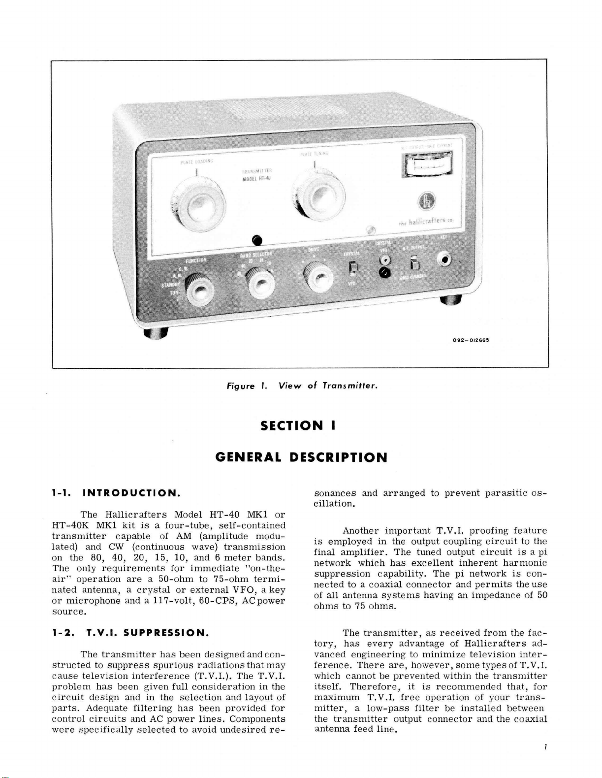
Figure
GENERAL
HT-40
self-contained
(amplitude
wave)
immediate
external
consideration
avoid
transmission
and 6 meter
to
75-ohm
VFO, a key
60-CPS,
designed
radiations
(T.V.I.).
been
lines.
The
and
provided
Components
undesired
1.
View
SECTION
MK1
or
modu-
bands.
"on-the-
termi-
AC
power
and
con
that
may
T.V.1.
in
the
layout
of
for
re-
of
Transmitter.
I
DESCRIPTION
sonances
cillation.
Another
is
employed
final
amplifier.
network
suppression
nected
of
all
ohms
tory,
-
vanced
ference.
which
itse
maximum
mitter,
the
antenna
which
to a coaxial connector
antenna
to
75
The
has
engineering
There are,
cannot
lf.
Therefore,
a low
transmitter output
feed
and
arranged
important
in
the
The
has
capabi
systems
ohms.
transmitter,
every
T.
be
prevented
V.1.
-pass
line.
advantage
free
to
prevent
T.V.1.
output
excellent
lit
to
however,
it
coup
tuned
filter
output circuit
y.
The
having
as rec
minimize
within
is
recommended
operation
be
connector and
proofing
ling circuit
inherent
pi
network
and
permits
an
impedance
eived
of Halli
television
some
types
the
of
installed
parasitic os-
feature
to
the
is a pi
harm
onic
is
con-
the
use
of
from
the fac
crafters
transmitter
your
the
ad-
inter-
of
T.
V.l.
that,
for
trans-
between
coaxia
50
-
l
Page 4
TECHNICAL
SPECIFICATIONS
TYPES
FREQUENCY
FREQUENCy
POWER
AUDIO
DISTORTION •
HUM AND NOISE OUTPUT • • • • • • • • • • • • • • 40 DB
TUBES
POWER
OUTPUT
POWER
OF
EMISSION
AM
• •
••
••••
cw
.................
SELECTION
COVERAGE • • • • • •
INPUT
AM
••••
CW
••••
INPUT
•••••••••••
SOURCE • • • • •
COUPLING • •
CONSUMPTION • • • • • • •
•.•.••••••
••••••••
•
••••••••••••••••
•••
Amplitude
.
•••••
• • •
Continuous
• • •
Crystal
• 80, 40, 20, 15, 10,
•
••
75
watts
75
watts
0.004 V
••
8%
•
••
.•
at
•
Four,
105-125
Pi
network
175
watts
modulation
wave
controlled
peak
maximum
minimum
75%
modulation
or
more
plus
two
volts,
or
and 6 meter
power
at
input
below
silicon
60 CPS,
external
to
microphone
maximum
rectifiers
AC
VFO
bands
jack
output
RF
OUTPUT IMPEDANCE
CW
KEYING.
MICROPHONE
DIMENSIONS • • • • • •
NET
WEIGHT • • • • • • • • • . • . • • • • • • . . • 17
SHIPPING
Band
80
40 7
20 14
15
• • • • • • • • • • • • . • • • • • • • •
INPUT.
WEIGHT • • • • • • • •
Transmitter
••••••••.•••••
• •
••
3.5
MC
MC
MC
21 MC
•••••••••••
•••••••••••
FREQUENCY COVERAGE
Frequency
to 4 MC
to
7.3
to
14.35
to
21.45 MC 7000 KC
Range
MC
MC
•••
50
to
75
ohm
phenol
Panel
connector
Rear
Amphenol
7-3/16"
19
83-1SP
mounted
chassis
pounds
pounds
coaxial
1/4"
mounted
75-MC1F
high,
13-3/8"
Crystal
connector
connector
key
jack
accepts
plug
microphone
connector
wide,
or
VFO
3500 KC
7000 KC to 7300
7000 KC
to
to
to
accepts
standard
receptacle
8-1/4"
Frequency
4000 KC
KC
7175 KC
7150 KC
Am-
2-
deep
Range
10
6 50
Note:
1000 KC = 1 MC
2
28 MC
MC
to
29.7 MC 7000 KC
to
54 MC 8333 KC
to
7425 KC
to
9000 KC
Page 5
SECTION
II
INSTALLATION
2-1.
UNPACKING.
Mter
it
closely
occurred
be
carrier
check
during
apparent,
stating
all
structions
2-2.
LOCATION.
The
provides
adequate
circulation
Avoid
on
2-3.
excessively
or
near
POWER
The
105-volt
to
consumption
If
in
contact
prior
an
AC
er
cord
can
unit,
2-4.
CRYSTAL-VFO
The
two
pin
jacks,
commodate
separation
unpacking
for
any
possible
transit.
file a claim
the
shipping
before
unit
of
removing
should
air
radiators
SOURCE.
transmitter
125-volt,
is
175
IMPORTANT
doubt
your
to
inserting
power
into
cause
extensive
requiring
CRYST
mounted
.093
"diameter
(similar
extent
labels
be
space
through
warm
and
60
watts.
about
local
outlet.
the
wrong
costly
AL-
VFO
to
type
the
transmitter,
damage
Should
which
any
immediately
of
damage.
and
tags
or
destroying
placed
around
in a location
it
the
cabinet
locations
heating
is
designed
cycle,
the
vents.
AC
power
current.
power
the
power
Plugging
power
damage
repairs.
RECEPTACLE.
receptacle
on
the
front
pins
with
FT-243
crystal
examine
may
sign
of
with
Carefully
for
special
to
permit
openings.
such
as
to
operate
source,
company
plug
into
the
pow-
source
to
the
consists
panel,
1/2"
have
damage
the
in-
them.
that
free
those
on
Power
of
to
ac-
center
holder).
When
high
(hot)
jack
and
2-5.
The
closed
provides
or
an
automatic
the
KEY
nected
strip
located
tacts
are
when
the
2-8).
2-6.
rear
of
bulkhead
type
75-MC1F
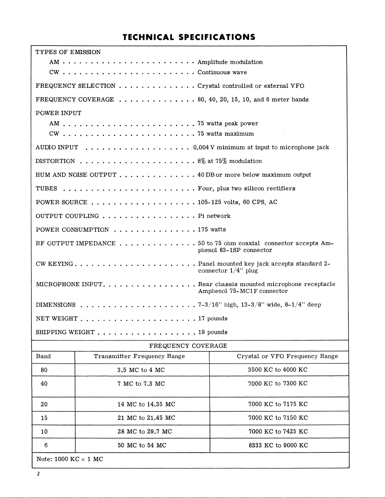
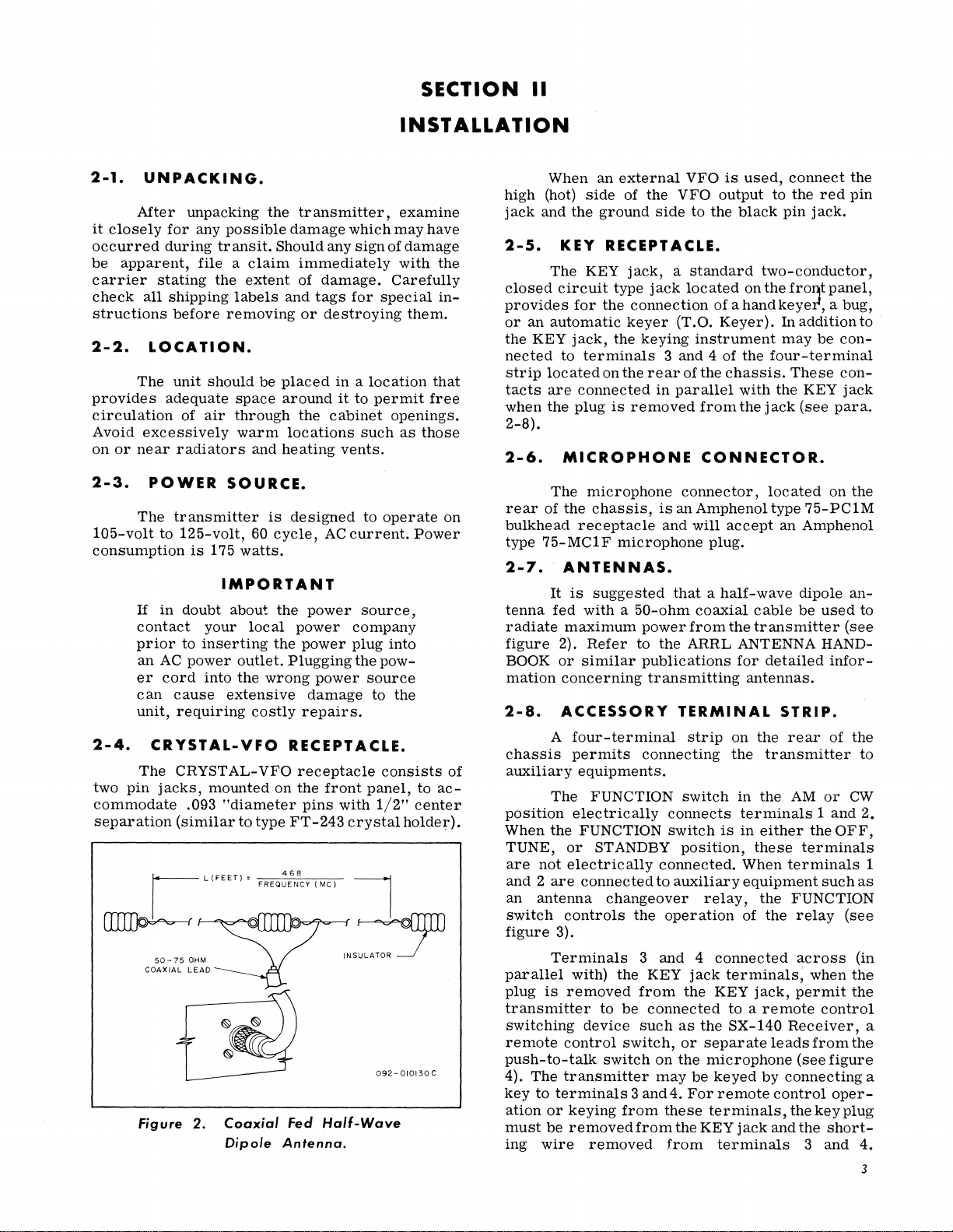
2-7.
tenna
radiate
figure
BOOK
mation
2-8.
chassis
auxiliary
position
When
TUNE,
are
r----
I
L
(FEET)
• I
FREQUENCY
468
(MC)
I
not
and 2 are
an
antenna
switch
~"f-M~'="',,{L.~l'Jo..A.A..LJ~,=,,~--rINS~
COAXIAL LEAD
figure
parallel
plug
is
transmitter
switching
remote
push-to-talk
4),
The
key
to
ation
or
must
be
ing
wire
Figure
2.
Coaxial
Dipole
Feci
Half-Wave
Antenna.
092-010130C
an
external
side
of
the
the
ground
KEY
RECEPTACLE.
KEY
jack, a standard
circuit
for
type
the
connection
keyer
jack,
the
keying
to
terminals 3 and
on
the
rear
connected
plug
is
removed
MICROPHONE
The
microphone
the
chassis,
receptacle
microphone
ANTENNAS.
It
is
suggested
fed
with a 50-ohm
maximum
2).
Refer
or
similar
concerning
ACCESSORY
A
four-terminal
permits
power
to
publications
transmitting
connecting
equipments.
The
FUNCTION
electrically
the
FUNCTION
or
STANDBY
electrically
connected
changeover
controls
the
3).
Terminals
with)
removed
device
control
the
to
3
KEY
from
be
connected
such
switch,
switch
transmitter
terminals 3 and
keying
removed
from
from
removed
VFO
is
used,
VFO
output
side
to
the
black
jack
located
(T.O.
on
of
ahandkeyer, a bug,
Keyer).
instrument
4 of
the
of
the
chassis.
in
parallel
with
from
the
CONNECTOR.
connector,
is
an
Amphenol
and
will
accept
plug.
that a half-wave
the
coaxial
from
ARRL
cable
the
transmitter
ANTENNA HAND-
for
antennas.
TERMINAL
strip
on
the
the
switch
connects
switch
position,
connected.
to
auxiliary
operation
in
the
terminals 1 and
is
in
either
these
When
equipment
relay,
the
of
and 4 connected
jack
terminals,
the
KEY
jack,
to a remote
as
the
SX-140
or
separate
on
the
microphone
may
be
keyed
4.
For
remote
these
terminals,
the
KEY
jack
from
terminals
connect
to
the
pin
red
jack.
the
pin
two-conductor,
the
fro'"'t
panel,
In
addition
may
be
con-
four-terminal
These
the
jack
located
type
an
con-
KEY
jack
(see
para.
on
the
75-PC1M
Amphenol
dipole
be
an-
used
(see
detailed
STRIP.
rear
infor-
of
the
transmitter
AM
or
CW
the
OFF,
terminals
terminals
such
FUNCTION
the
relay
across
permit
when
(see
(in
the
the
control
Receiver,
leads
from
the
(see
figure
by
connecting
control
and
the
the
3
oper-
key
short-
and
plug
to
to
to
2.
1
as
a
a
4.
3
Page 6
SECTION
III
3-1.
tary
switch,
of
operation
FUNCTION
The
FUNCTION
is
used
as
1.
OFF
from
2. TUNE
oscillator
the
modulator
ges.
DRIVE
on
the
meter.
3.
ST
ANDBY
the
DC
from
is
made
refer
CONTROL.
control, a five-position
to
select
indicated.
position:
the
power
position:
and
Grid
current
control
RF
OUTPUT
position:
power
the
internal
for
to
paragraph
the
AC
power
transformer
power
buffer
and
final
is
for
maximum
the
supply
circuitry.
remote
2-8.
OPERATING
ro-
transmitter
is
disconnected
is
applied
stages
amplifier
adjusted
- GRID CURRENT
negative
is
disconnected
control
mode
primary.
to
the
but
not
to
sta-
with
the
indication
side
of
Provision
switching,
CONTROLS
A unique
allows
through
ST
ANDBY
better
ing
4.
5.
3-2.
The
multi-section
voltage
from
AM
oscillator,
final
CW
to the
and to the
screen
tube which, in the
as a series
BAND
BAND
NOTE
feature
current
the
to
bleeder
position,
regulation
STANDBY
position:
buffer,
amplifier
position:
buffer
oscillator
grid
through
regulator
SELECTOR
SELECTOR
rotary
switch
of
the
be
to
power
and
power
and
used
thus
final
CW
power
constantly
w
hen
supply
fed
in
the
providing
when
switch-
AM
or
CW.
is
applied
speech
amplifier,
modulator
is
applied
directly
amplifier
and
final
amplifier
the 6DE7
position
modulator
functions
tube.
CONTROL.
is a six-position,
to
select
the
to
the
stages.
plate,
pro-
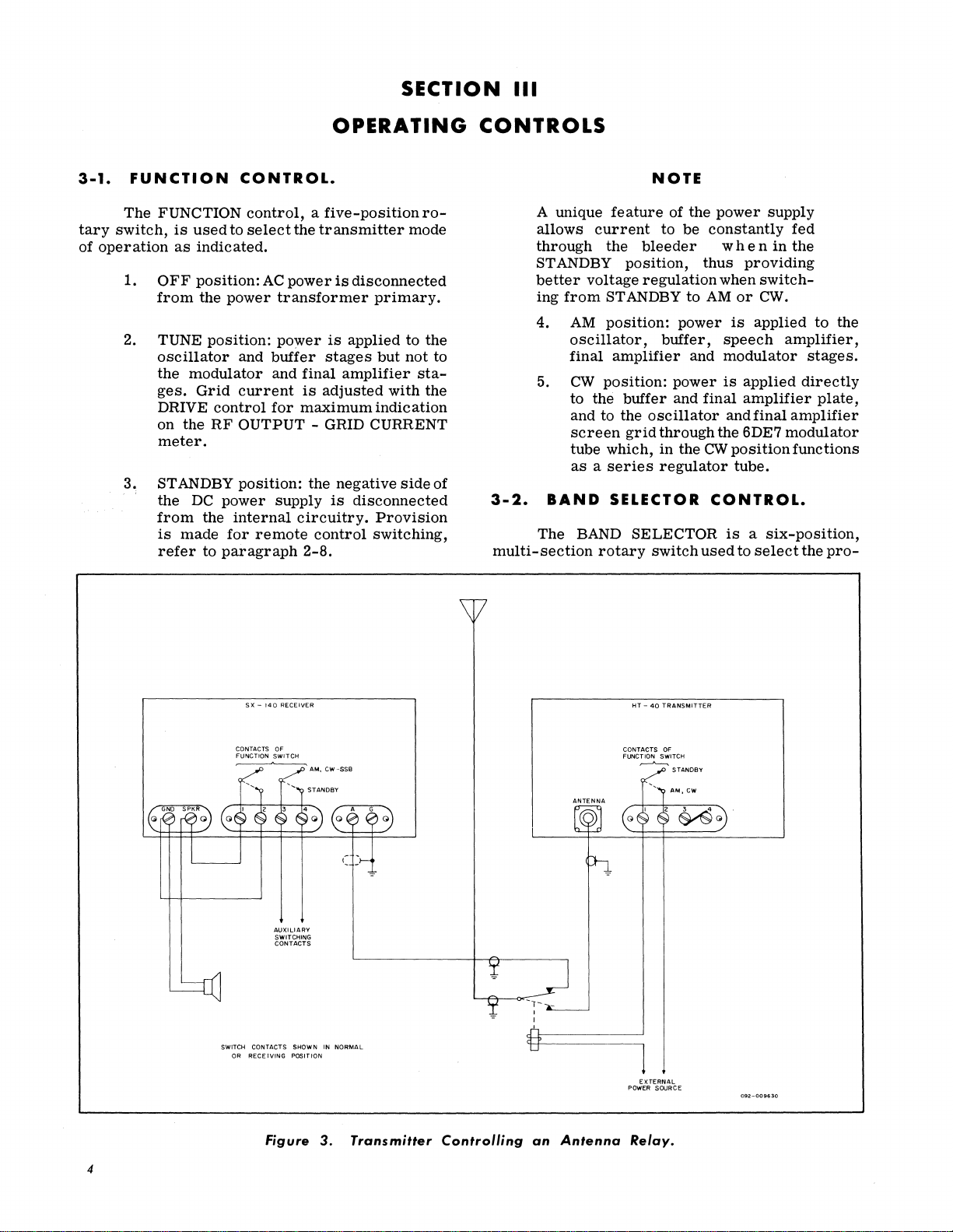
SX -140
RECEIVER
CONTACTS
OF
FUNCTION
SWITCH
AUXILIARY
SWITCHING
CONTACTS
SWITCH CONTACTS SHOWN IN
OR
RECEIVING
POSITION
Figure
NORMAL
3.
Transmitter
Controlling
an
Antenna
HT -40
TRANSMITTER
CONTACTS OF
FUNCTION SWITCH
~
STANDBY
EXTERNAL
POWER SOURCE
Relay.
4
Page 7
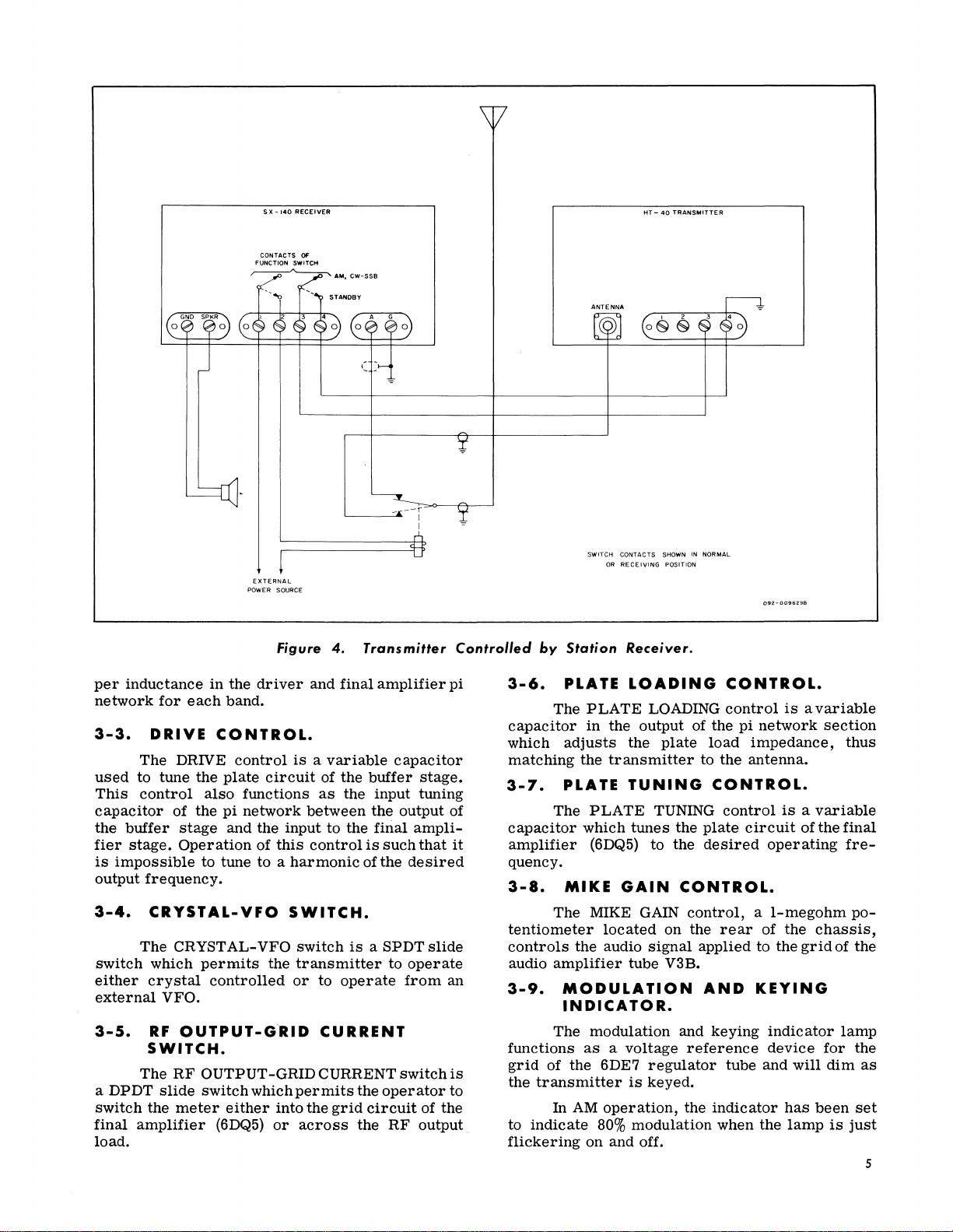
S x -
140
RECEIVER
HT -
40
TRANSMITTER
per
inductance
network
3-3.
used
This
capacitor
the
fier
is
output
3-4.
for
each
DRIVE
The
DRIVE
to tune the
control
of the
buffer
stage.
stage
Operation
impossible
frequency.
CRYSTAL-VFO
The CRYSTAL-VFO
switch
either
external
3-5.
which
crystal
VFO.
RF
OUTPUT-G'RID
SWITCH.
The
RF
a DPDT
switch
final
slide
the
meter
amplifier
load.
EXTERNAL
POWER
SOURCE
in
the
Figure
driver
and
4.
Transmitter
final
amplifier
band.
CONTROL.
control
plate
also
functions
pi
network
and the input
to tune to a
is a variable
circuit
of
this
harmonic
of the
as
between
control
buffer
the input tuning
the
to
the
final
is
of
such
the
SWITCH.
permits
controlled
switch
the
transmitter
or
is a SPDTslide
to
to
operate
CURRENT
OUTPUT-GRID CURRENT
switch
which
either
(6DQ5)
permits
into the
or
across
grid
the
operator
circuit
the
RF
pi
capacitor
stage.
output of
ampli-
that
it
desired
operate
from
an
switch
is
to
of the
output
Controllecl
3-6.
capacitor
which
matching
3-7.
capacitor
amplifier
quency.
3-8.
tentiometer
controls
audio
3-9.
functions
grid
the
to
flickering
SWITCH CONTACTS
OR
RECEIVING
by
Station
PLATE
The
adjusts
PLATE
The
Receiver.
LOADING
PLATE
in
LOADING
the output of the
the
the
transmitter
TUNING
PLATE
which
tunes
(6DQ5) to the
MIKE
GAIN
The MIKE GAIN
located
the audio Signal
amplifier
tube V3B.
MODULATION
INDICATOR.
The modulation and
as a voltage
of
the
transmitter
In
AM
indicate
on
6DE7
80%
regulator
is
keyed.
operation,
modulation when the
and off.
SHOWN
IN
NORMAL
POSITION
092-00962.9B
CONTROL.
control
pi
network
plate
load
to
impedance,
the
antenna.
CONTROL.
TUNING
the
control
plate
circuit
desired
operating
CONTROL.
control, a I-megohm
on the
rear
applied
AND
keying
reference
tube
the
indicator
of
to
KEYING
indicator
device
and
is a variable
section
thus
is a variable
of
the
final
fre-
po-
the
chassis,
the
grid
of the
lamp
for
the
will
dim
has
been
set
lamp
is
just
as
5
Page 8
'"
::n
CQ
c:
;
~
....
..,
Q
::s
'"
3
-
CD
-
..,
."
..,
0
::s
-
."
Q
::s
CD
-
()
0
::s
..,
-
0
;;;-
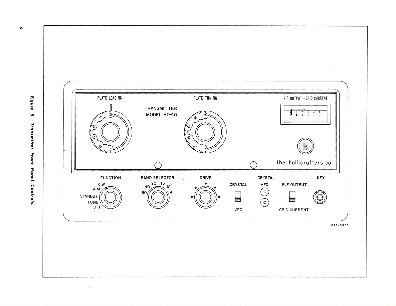
PLATE
LOADING
TRANSMITTER
MODEL
HT-40
0
FUNCTION BAND SELECTOR DRIVE CRYSTAL
20
0
15
6
.@.
C.w.
STAND;~M~
TUNE
OFF
4@
80
PLATE
TUNING
•
R.F.
OUTPUT -GRID
r:=r
II
the
0
CRYSTAL
VFO
G
~
G
VFO GRID CURRENT
hallicrafters
R.
F.
OUTPUT
~
CURRENT
~
®
@
KEY
II
co.
092-
012051
Page 9
SECTION
IV
OPERATION
4-1.
has
adjustment
does
ted
ments
mitter
4-2.
formed
CW
GENERAL.
The
tuning
been
simplified
to the
not
mean
successfully
are
made. A clean
requires
TUNING
CW
OPERATION.
The
following tuning
prior
mode.
procedure
in
desired
that
the
transmitter
when only
good
operating
PROCEDURE
to
operating
EQUIPMENT REQUffiED
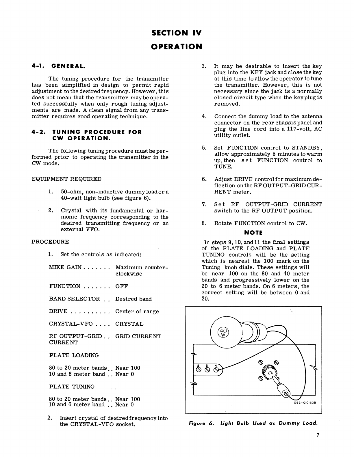
1.
2.
50-ohm,
40-watt
Crystal
monic
desired
external
non-inductive
light
bulb
with
frequency
transmitting
VFO.
PROCEDURE
1.
Set
the
controls
MIKE
GAIN.
. . • .
FUNCTION . . . . .
BAND
SELECTOR
for
design
to
frequency.
rough
signal
from
technique.
procedure
the
transmitter
(see
its
fundamental
corresponding
frequency
as
indicated:
..
Maximum
clockwise
..
OFF
..
Desired
the
transmitter
permit
However,
may
tuning
any
FOR
must
dummy
figure
band
rapid
be
opera-
adjust-
trans-
be
per-
in
load
6).
or
harto
or
counter-
this
the
or
the
an
3.
It
may
be
plug
into
at
this
time
the
transmitter.
necessary
closed
circuit
desirable
the KEY
to allow the
since
type when
to
jack
and
operator
However,
the
jack
insert
close
this
the
the
to
is
key
key
tune
is a normally
the
key
plug
not
is
removed.
4.
5.
Connect
connector
plug
utility
Set
allow
up,
the
the
dummy
on the
line
cord
rear
into a
load
chassis
outlet.
FUNCTION
control
approximately 5 minutes
then
set
FUNCTION
to
the
antenna
panel
and
117-volt,
AC
to STANDBY,
to
warm
control
to
TUNE.
6.
Adjust
flection
a
7.
RENT
Set
switch
8.
Rotate
In
steps
of
the
TUNING
which
Tuning knob
be
near
bands
20
to 6 meter
correct
DRIVE
on the
meter.
RF
to the
FUNCTION
9,10,
PLATE
controls
is
nearest
dials.
100 on
and
progressively
setting
control
RF
for
OUTPUT-GRID
OUTPUT-GRID
RF
OUTPUT
control
NOTE
and
11
the
final
LOADING and
will
be
the
the 100
These
the
mark
settings
80 and 40
lower
bands.
will
On 6
be
between
meters,
maximum
CUR-
CURRENT
position.
to CW.
settings
PLATE
setting
on
the
will
meter
on
the
the
0 and
de-
20.
DRIVE . . . . • . . .
CRYSTALRF
OUTPUT-GRID..
VFO
CURRENT
PLATE
80
10
PLATE
80
10
2.
LOADING
to
20
meter
and 6 meter
TUNING
to
20
meter
and 6
meter
Insert
the
crystal
CRYST
bands
band
bands
band
AL-
. .
of
..
..
::
..
..
desired
VFO
Center
of
CRYSTAL
GRID
CURRENT
Near
100
Near
0
Near
100
Near
0
frequency
socket.
range
into
Figure
6.
Light
Bulb
Used
as
092-
Dummy
0101528
Load.
7
Page 10

9. Adjust
maximum
ter.
10. Adjust
maximum
ter.
PLATE
output
PLATE
output
TUNING
indication
LOADING
indication
control
on the
control
on the
for
me-
for
me-
dure
for
CW
operation
through
step
12
except
that
plugged in. The following
the tuning of
the
transmitter
1. Connect the
connector
on the
in
Paragraph
the
CW
procedure
for
AM
microphone
rear
of the
4-2,
key
need
will
complete
operation:
to
the
chassis.
step
not
MIKE
1
be
11.
12.
13. Rotate the
14.
4-3.
TUNING
AM
The
for
AM
operation
Repeat
output
meter
Turn
TION
load
steps
is
obtained; note the
reading.
transmitter
control,
and
connect
tenna.
FUNCTION
and note output
impedance
as
that
indication
same
line
is
noted;
of the
as
that
open, a
if
antenna
is
will
noted
proximately
noted.
If
the
proper
meter,
the
CW
operation.
OPERATION.
procedure
the
PROCEDURE
for
is
identical
9 and 10
off
until
with
disconnect
the
transmitting
control
indication.
If
approximately
dummy
be
higher
zero
indication
tr
ansmitter
load,
approximately
in
step
indication
line
is
indication
is
FOR
tuning the
to the
tuningproce-
maximum
approximate
the FUNCthe dummy
an-
to
CW
the
antenna
the
same
the
meter
the
11.
If
antenna
will
be
shorted,
obtained
is
will
ready
ap-
be
on
for
transmitter
2. Rotate the FUNCTION
note
the
approximately
noted
in
step
3. While
the
talking
desired
phone and
dicator
control
lamp
vides
Never
lamp,
clockwise
just
75%
over-modulate
Over-modulation
4-4.
eration
crafters
tains
centers
formed
continuous
ulation
SERVICE
QUESTIONS.
For
of
dealer.
an
extensive
where
promptly
indicator
any
further
the
any
bright
OR
transmitter,
The
and
control
meter
indication,
one
fourth
11
of
paragraph
in a normal
distance
observing
the
voice
from
the modulation
advance the MIKE GAIN
until
the
flickers
to
on and off.
90%
AM
the
will
be
flickering
modulation.
transmitter.
indicated
of
the
lamp.
OPERATING
information
regarding
contact
Hallicrafters
system
required
efficiently
Company
of
authorized
service
at a nominal
to
it
should
indication
4-2.
level
the
micro-
indicator
This
by
mod-
your
Hallimain-
service
will
be
AM;
be
at
in-
pro-
op-
per-
MODULATION FREQUENCY
8
APPROX.
75%
MODULATION
MODULATION
Figure
FREQUENCY
7.
Carrier
MODULATION FREQUENCY
100%
OVER
Modulation
MODULATION
\J
Patterns.
100
% MODUL.ATION
092-010131
Page 11

charge.
ters
location
or
factory
All
display
of
telephone
Do
not
unless
Hallicrafters
sibility
for
The
privilege
tion of
corporate
of making
equipment
these
Hallicrafters
the
sign
the
one
nearest
directory.
make
any
instructed
Company
unauthorized
Hallicrafters
revisions
and
assumes
revisions
Authorized
shown
at
you,
service
to
will
not
shipments.
Company
in
earlier
the
consult
shipments
do
so
accept
Service
right.
your
by
the
For
dealer
letter.
respon-
Cen-
to
The
the
the
reserves
in
cur~ent.prod~c
no
oblIgatIon to
models.
the
10-
THEORY
5-1.
circuit
fundamental
through,
produce
Circuits
operation
20
wave)
tion
phone
5-2.
modified
In
plate
in
ments
shunted
The
mon
tion. Coupling
grid
nal
jacks
to the
connected
(6CX8) and
connected
the VFO
VFO
to STANDBY and
GENERAL.
The
transmitter
or
external
Signal
or
operated
the
desired
are
employed
at
any
15 10 and 6
, , , . .
or
AM
(amplitude modulation).
or
carrier
control
utilizes a built-in
VFO
for
generating
that
is
to
as a harmonic
output
desired
meter
frequency
in
the
frequency
bands
modulation
be
amplified
generator
on
transmitter
in
on
CW
Screen
is
employed
the
each
the
(continuous
transmission.
CRYSTAL-OSCILLATOR.
The
triode
Pierce
this
circuit
to
the
series
with
consist
by a
plate
circuit
fixed
plate
is
accomplished
When
VFO,
the
and the VFO
pin
jacks.
through
through
position
position,
section
Type of
feedback
grid
by
means
the
crystal.
of a
lOOK
50
mmf
utilizes
load
from
operating
crystal
output
The high
the
the
ground
the
to
the
triode
does
of
VI
crystal
energy
of a 5000
The
ohm
capacitor
a 2. 5
for
all
frequencies
the
oscillator
with a 50
the
transmitter
is
removed
terminals
side
red
jack
side
black
jack
RF
ground. When
section
not
operate.
(6CX8)
oscillator
is
fed
mmf
grid
grid
return
loading
MH
choke
plate
mmf
capacitor.
from
are
of the VFO
to the
of
the
and
grid
VFO
switch
(VIA)
is
circuit
as a com-
with
connect~d
Sl
is
SECTION
oscillator
desired
straight
to
band.
to
permit
80,
40,
1OJec-
for
used
in
circuit.
from
the
capacitor
ele-
resistor
capacity.
of
opera-
to
buffer
exter-
the
pin
output
output
is
switched
IS
of V1B
is
Sl
in
in
the
OF
OPERATION
5-3.
as a buffer
oscillator
lified
C. The
UH
tube
arate
put
work
connected
proper
sible
with the DRIVE
bility
tenna
imum.
a
5-4.
beam
through
bands
band. The
shunt-fed
section
with
nated
matching
the antenna. A
through
separate
so
that a minimum
tween
circuit
5-5.
a
basic 5 mil
The
functions:
V
BUFFER-MULTIPLIER.
The pentode
multiplier.
circuit
or
multiplied
buffer
choke
coupled
V2
(6DQ5) by
inductances
is
tuned
with
output
is
to
selection
to tune to a
of
undesirable
and
keeps
FINAL
The
final
powered
amplifier
and
as a frequency
final
RF
network. The input of the
the
PLATE
with the
the
10
meter
coil
them. A sensitive
to
measure
RF
OUTPUT-GRID
METER.
The
RF
meter
and
section
The
to
the
by
this
plate
load
to
the
means
for
each
the DRIVE
terminated
the
6DQ5
grid
of
coils
harmonic
capacitor.
signals
television
AMPLIFIER
amplifier
pentode
tube,
on the 80
amplifier
choke
capacitively
TUNING
PLATE
plate
impedance
tapped
coil
bands;
(L9)
connected
of
mutual
grid
OUTPUT-GRID
movement
its
circuitry
of
VI
signals
grid
of the
stage
consists
grid
of the
of a
pi
band.
capacitor
with a 9
circuit.
in
each
of
the
This
being
interference
STAGE.
stage,
operates
doubler
plate
capacitor,
LOADING
to
(L10)
the 6
meter
at
inductance
meter
(M1)
current
CURRENT
CURRENT
graduated
perform
(6CX8)
are
is
fed
buffer
operating
of a
shunt
final
network
The
network
and
mmf
Because
band,
it
output
reduces
fed
utilizing
as a straight
through
on
the 6 meter
load
consists
coupled
network
and
capacitor
the
impedance
isusedfor
band
right
angles
is
used
and
output
in 5 units
two
operated
from
the
and
amp-
in
class
fed
100
amplifier
with
sep-
in-
the
net-
capacitor
ofthe
is
impos-
frequency
the
possi-
to
the
~
to a
m1O-
a 6DQ5
10
meter
of a
to
the
pi
is
tuned
is
termi-
for
of
the 80
uses
to L10
exists
in
be-
this
power.
meter
is
(0-5).
important
a
9
Page 12

1.
2. With
5-6.
SPEECH
& SERIES
The s peech a
stem con
sis
(12AX8) and
coupl
ed
and
quate
sig
nal
sec
tion
of
si
stan
ce
and acts
The scre
element)
thode
co
mponent
fu
ll
tube
follower
to
the scr
thr
ough a
en
becomes
With
the
switch
RENT
c
i
ti
antenn
on
18 wa
for
36
position,
urrent
ndicates
swit
on,
the output
a can
the
met
tts
e,
if
watts
can
approximately 1 milliampere.
ch
er
when
a
ar e
antenna (2.0 x 18
AMPLIFIER,
VOLTAGE
mplifi
84
the
final
be
measured; each
84
in
the
power
be
measured.
represents
the
V8WRi
deflection
bein
g delive
==
36).
er
section
in
the
GRID
amplifier
division
RF
OUTPUT
delivered
Each div
approximatel
s 1 to 1. Ther e-
of 2 is indicat
r ed to
MODULATOR,
REGULATOR.
of
the
audio
ts of the two triode sections of V3
one
tr iode
operated
inp
ut
to the modul
V4). T
he modulatot' has a low pl
as a high
impedance
an appr
impedance. The
of
the c
een
.5
mfd
section
in
cas
cade
level cathode foll
of the 6DQ5 (the
eciab
atho
de foll
of the
final
capacitor
of
V4 (6DE7) RC
to
deve
lop
an
ator (seco
nd
triode
ate
modulated
le po
rtion
of the
audio frequency
ower is
amplifier
applied
(6DQ
to permit modula-
CUR-
grid
posi-
to
the
isi
on
ed,
the
sy-
ade-
re-
ower .
ca-
in
5)
tion
of
the
screen.
phone
(V1A)
c
ould
jack
and
eliminates
be
caused
During CW
section
age
y
to
c
ircuits.
5-7.
obtained
of
Regul
the crys
POWER
The
the
ator
tal
DC volt
by rectifying the AC vo
secondar y of
wave volt
ode
pl y
together
to
rs
age
rec
tifi
is
accomplish
with
.
er s. A
Another
transformer
th
e tub
es
in the tr ans m
eve
To pr
ing conduct
power lin
pow
er tra
ed back thr
e,
nsformer
An
RF
filter
between
the
grid
of
the
by
6DE7
Tube
osc
illator
distortion
RF
across
operation,
is
connec
and
supplies Reg
and
MIKE
in
the
the
ted
fin
preamplifier
the
system
microphone jack.
modulator
as a
series
ulated Volta
al a
mplifi
SUPPLY.
age
to
opera
te the
transmitt
lta
ge acr
the power transformer
T1
doubler circuit using two s i
deq
uate
ed
the
choke and out
seco
fur
nis
filterin
by the voltage doubler circuit,
ndary
hes filame
g of
windin
nt vo
the power
put
filter cap
g of the pow
lta
ge for a
itter.
nt television
an
LC filt
interference
ough
the
er
is conn
power co
ected
primar y.
the
micro-
er scre
oss
wit
h a fu
lico
fr om be-
r d to
across
which
(V4B)
Volt-
ge
en
er
is
the
lln di sup-
aci
er
ll
of
the
the
-
LlO
OU
TPUT PL ATE
TANK COIL
110
M TO BOM i
--+
T I
-----
PLATE L
C25
OAD
CAPACIT OR
-,.~,.---
ING
PI
LIGHT
LMI
V2
6005
LOT
L9
OUTPUT
PLATE
TANK CO
16M)
CI 7
PLATE T UNI NG
CAPACITOR
LI
3
OUTPUT
PLATE
" 5 "
CHOKE
MI
METER
0 9 2 -
Ll2
FILTER
CHOKE
VI
6CXB
V4
GO£?
012
663
IL
LM2
M
ODUL
ATI ON
INDICATOR
10
Figure
8. Top
View
of
Transmitter
Chassis.
Page 13

SECTION V I
6-1.
CHASSIS
Remove
from
the
rear
including
the
front
net.
6-2.
TUBE
REPLACEMENT.
Access
obtained
(see
refer
6-3.
by
para.
to
6-1).
figure
TROUBLE
In
this
removing
transmitter,
communications
MICROPHONE
CONNECTOR
REMOVAL.
the
10
of
the
panel,
AND
to
the
For
8.
SHOOTING.
equipment,
J 4
No.6
cabinet.
out
PILOT
tubes
the
chassis
tube
thread
forming
Slide
the
front
LIGHT
and
pilot
from
and
pilot
as
in all
maintenance
RI6
MIKE GAIN
SERVICE
screws
the
chassis,
of
the
cabi-
light
may
be
the
cabinet
light
location
well-designed
and
re-
AC
CESSORY
TERMINA L S
TRIP
DATA
pair
problems
and
replacing defective
this
nature
tube
substitution.
faulty
for
proper
values.
Table 1 provides
the
transmitter.
incomplete
proper
can
only
and a complete
H
owever,
pretested
table
will
in
most
XV2
are
tubes
occur,
as
operation
be
dete
each
before
provide
instances.
FRI
25MC
FILTER
voltage,
are
genera
easily
Should
refer
It
is
there
are
of
any
rmined
knowledge
component
it
is
adequate
ANTENNA
CO
NNECT
lly
confined
tubes.
isolated
malfunctions
to
the
resistance,
suggestions
possible
numerous
piece
of
with
elaborate
of
of
placed
in
servicing
J5
OR
to
Malfunctions
and
corrected
schematic
and
for
that
this
causes
equipment
instruments
the
entire
the
transmitter
the
unit,
information
checking
other
than
diagram
capacity
servlclllg
table
for
which
circuit.
thus
of
by
is
im-
is
the
XV3
XVI
XV4
J 3
KEY
JACK
54
RF
OUTPUT
GRIO
CURRENT
BLACK
JACK
Figure
JI
PIN
RED XTAL
PIN
JACK
9.
J2
Bottom
VF
51
O
CI5
DRIVE
CAPACITOR
View
S2A
of
Transmitter
l6
L7
115M) 110M) 16M)
LB
Chassis.
092
S2C
S2B
L3
180M)
l4140MI
l
5120
- 0 12664
M)
11
Page 14

Table
l.
Trouble
Shooting
Information.
Symptom
No output on any band
No
AM
modulation on any band;
operation functions
No
output on
Schematic
Symbol
3,
8, 10, 11,
C1,
C2,
9,14
5,
6, 13, 16, 20, 21, 23, 24,
C4,
30,
33,
C7
C15
C17
C18
C19 9
C22
C25
C26 100
C29,
35
C32 0.1
C34
C36
C37
C38
C44, 45, 46, 47
C50 750
C51 22
R1,4
R2 47K
R3,1l
R5 470
R6, 20 12K
R7 2.5Kohm, 7W, Wirewound
R8,13
R9 39K
RIO
R12
R14 2.2
Description
CAPACITORS
12,31,39,
0.005
mid.,
Cer.
Disc
50
mmi.,
Cer.
Disc
40, 41, 42, 43
0.001
mId.,
Cer.
Disc
0.01
mid.,
Cer.
Disc
6-37
mmf.,
DRIVE
14-140
mmf.,
PLA
TE
0.001
mid.,
Cer.
Disc
mmi.,
Duramica
100
mfd.,
Electrolytic
33-1290
PLA
TE
mm!.,
Cer.
Disc
100
mm!.,
Cer.
Disc
mfd.,
Molded
om
mid.,
Cer.
Disc
0.47
mid.,
Molded
0.005
mfd.,
Cer.
Disc
0.05
mfd,
Disc
40
mfd.,
Electrolytic
mmi.,
Duramica
mmf.,
Duramica
lOOK
ohm
ohm
22K
ohm,
ohm
ohm,
1 megOhm
ohm,
10K
ohm
4.7K
ohm
megohm
anyone
48, 49
500V, GMV,
600V, 10% MIKE GAIN
27,28,
1000V, GMV, R23
500V, +80-20% R25
Variable,
Variable,
TUNING
3000V, 20%,
300V,
2%,
12 VDC,
mmi.,
Variable,
LOADING
2000V, 10%,
1000V, 20%,
600V, 10%
Paper
1400V, GMV,
400V, 10%,
Paper
1000V, 20%,
50V,
Ceramic
350 WVDC,
300V,
2%,
300V,
2%,
'RESISTORS
2W
2W
1W
(AM
or
properly
band.
SERVICE
Hallicrafters
Part
Number
047-100442
047-100744
047-101172
047-100224
048-000499
048-000496
047-100397
481-131090
045-100619
048-000519
047-001601
047-001397
499-031104
047-200752
046-001337
047-100523
047-001144
045-000723
481-161751 L13
481-151220
451-252104
451-252473
451-652223
451-252471
451-652123
024-001357
451-252105
451-352393
451-252103
451-252472
451-252225
CW)
CW
VI
TI,
or
LI6
1.
2.
components
Shorted antenna.
3.
V3
1.
2.
1.
or
Microphone
in
the audio
Defective
Possible
V2 defective.
and/or
V4
defective.
interstage
Cause
associated
defective.
and/or
system
band.
2. BAND
Oscillator
3.
REPAIR
Schematic
Symbol
17,
19
R15,
R16
R18
R21
R22
R24 1K
R26 20 ohm,
R27, 28 56K
R29 68K
R30
R31 100 ohm, 5W, Wirewound
'RESISTORS
otherwise
L1 2.5 MH, 125 MA;
L2
L3
L4
L5
L6
L7
L8
L9
L10
L11 1 MH, 200 MA,
L12 Choke,
L14,15
L16
L17 25
PSI
Tl
Sl
S2A, B, C Switch, Rotary; BAND Shield,
S3
S4
Description
'RESISTORS
470K
ohm
1
megohm,
10
lOOK
2.2K
5.6K
56K
100
specified.
COILS AND TRANSFORMERS
100 UH, 200 MA;
Coil,
Network
Coil,
Network
Coil,
Network
Coil,
Network
Coil,
Network
Coil,
Network
Coil,
Coil,
(80
0.425
3.8
Coil,
Parasitic
Transformer,
Switch,
SELECTOR
Switch, Rotary;
FUNCTION
Switch,
PUT
Variable,
megohm
ohm,
1W
ohm
ohm,
1W
ohm
ohm
7W,
Wirewound
ohm,
2W,
ohm
ohm
1/2
are
10%,
Interstage
(80
M)
Interstage
(40
M)
Interstage
(20
M)
Interstage
(15
M)
Interstage
(10
M)
Interstage
(6
M)
Output
Tank
Output
Tank
thru
10
M)
Filter
MH;
Plate
UH;
Line
Choke
25
MC,
MC,
Parallel
Series
Choke
SWITCHES GRID
SPDT;XTAL-VFO
DPDT;
- GRID
CURRENT
(cont.)
20%
watt,
RF
RF
Pi
Pi
Pi
Pi
Pi
Pi
(6
RF
Output
Filter
Assy
Power
RF
PARTS
carbon
choke
choke
M)
Choke
Choke
Filter
OUT-
SELECTOR defective.
Crystal
LIST
Hallicrafters
Part
Number
451-252474
025-001949
451-252106
451-352104
451-252222
451-352562
451-252102
451-252563
024-001356
451-653563
451-252683
451-252101
445-012101
type
unless
053-000597
053-000644
051-003296
051-003297
051-003298
051-003299
051-003300
051-003301
051-003308
051-003302
053-000598
056-000446
053-200426
053-000607
051-003257
051-003256
053-000645
052-000852
060-200967
060-002413
060-002417
060-002260
Schematic
Symbol
J1
J2
J3
J4
J5
XV1,3,4
XV2
TAl
CR1,2
CR3
VI
V2
V3
V4 6DE7;
LM1
LM2
PL1
M1
N1
JACKS, SOCKETS AND CONNECTORS
power supply
associated
components
defective.
coil
for particular
defective.
Description
Jack, Pin;
Jack,
Jack,
Connector, Microphone
Connector, Coaxial
(Antenna)
Socket, Tube; 9-Pin
Socket,
Terminal
(4
TUBES,
Diode,
Doubler
Diode, Germanium (Meter
Circuit)
6CX8;
6DQ5;
12AX7;
Amplifier
Amplifier
and
Pilot
Modulation Indicator
Lamp,
Base,
Bracket,
Cabinet
Cable,
Foot,
Insulator,
and
Knob, FUNCTION
BAND
Knob, DRIVE
Knob, PLA
AND
Line Cord
Lock, Line Cord
Meter,
Neon
Panel, Front
Shield,
Spacer
Washer,
(Stand Off
Mtg.)
Black
Pin;
Red
Phone;
KEY
Tube;
Board,
contacts)
LAMPS AND
Silicon
Circuit)
Type
Oscillator
RF
Output
Microphone
1st
3rd
Audio
Modulator
Lamp, Neon
Neon
MISCE LLANEOUS
Tube
Shield
Tube
Coaxial,
Plastic
Stand Off (L9
L10
mtg.)
SELECTOR
TE
PLATE
RF
OUTPUT
CURRENT
light,
type
Electrical
Tube
(Vl,
(C17
and
Flat
Insulator
Octal
Accessory
(Voltage
Type
1N295
and
and
2nd
Amplifier
(V1,
Mtg.
RG-58/U
and
LOADING
TUNING
NE-2H
3,
C25
Fiber
Hallicrafters
Part
Miniature
RECTIFIERS
1N3255
Buffer
Pre-
Audio
3,
4)
(V2)
-
4)
mtg.)
Number
036-000295
036-000294
036-100002
029-100566
010-100056
006-000947
006-000948
088-002411
019-002939-03
019-301980
090-901418
090-901420
090-900038
090-901419
039-000613
039-000673
069-001417
067 -008881
150-901138
087-100960
016-201072
008-006149
015-001725
015-001724
015-001735
087
-100078
076-200397
082-000493
039-000671
068-001232
069-001402
069-100430
073-003691
004-200522
12
Page 15

...
'"
:J-
eD
3
Q
::r,
...
o
Q'
IQ
..
Q
3
o
-
ANTENNA
=
RELAY
CONTROL
AUXILIARY
CONTROL
2'
{
{TerL-
~~
CI
LI
2.5
MH
C'
VIA
1/2-6CXB
OSCILLATOR
l
C28
\
J47K
'"
£_~
IRI
*,g
R2
V3A
1/2.-12AX7
MIKE
PREAMPLIFIER
RI5
470K
*65V
Ilc30~
2
.)f-*
2f
-
RI4
51
'>::1illbl::T::AL;;---~L~II~-'---~
C49
ODS
-::r.
C2 *
50MMF T lOOK
IMH
~ggl
INPUT
J4
MIKE
RI2
4.7K 001
r-:>'-rr
..
-r'~-----,)f---:'T~~JrT~
RI3
C29
IMEG
100MMF 2,2MEG
50MMF
VIS
112-6CX8
190Y
C8
.0051'
L----V3--S-----~"'V:4=A~===V4=S======p-h
112-12AX7 V2-6DE7
1ST
AMPLIFlER
4~6~
*S5V
.001
1°°
AUDIO
~~2i
C33
CI4
50MMF
CI5
~~!
6-37Mt.'F-=
L2
100
UH
C13
1
22:32W
R
19
2ND
AUDIO
470K
AMPLIFIER
8
FM
EG
~-=-
001
" 2
10
~
~2
Ii
rl
'0
S2A
FRONT
'12y-12
lOA
r,~..2-
~
10
S2A
REAR
(SEE
NOTE
I }
I BAND SELECTOR I
430V
R7
V5K,7W
1/2-60E7
MODULATOR
t~6~
~500V
L'
~--LIO--~
L3
80
L4
40
L5
20
L6
15
LT
10
C26
IOQMMF
LI3
C37
005
r
~Tr-<I:::c8="'R,;:I~;;:NT"I-jf'I'::W_~
~;;5fl~~4
.425
J-
=
IKV
MH
9M~±
r S4!
76~
MI
_',
0
'Y
~
,
•.
001 X
~~,r
~
~~:+
C22
100
I5V
S3
FRONT
'--
____
~
~_c6~
9~1
6
::k~24
rOOI
~o'6
5W
CR3
C~~R22
,05
50V
2KV
2.2K
S2C
SECT 3
~~
*30V
R"
22K
2W
R23
5£'
IW
ANTENNA
I
PLI
117VAC
60CPS
~
Ll4
E~
f·o
i;
C41
OI
C43
f·OOI
S3
Ll5
ON/OFF
ON
OF
FUNCTION
TI
''''Li'~6-.3-V--X
4
15A J 2
~
R25
56K
LMI
SWITCH
REAR
swrrCH
R26
,--=2,"0'N-7W'--T--IC~Rf-'
195
VAC
MEASURED
ACROSS, TI
SECONDARY
Ll2
~r-=5H"-_T
C44
40
350V
r-:-
C45
40
350V
CR2
___
R27
56'
2W
20%
R28
56'
d~A
"t4",3"00,-V
'------"-,-,-,-,-++-J
__
"*",50,,,0,-,V
___
C46
40
350V
C47
40
350V
NI
NE-2H
LM2
NE-2H
~~
+--t---t+f-
RnR
#4
SWITCH
WAFER
"
TO
WAFER
S2A
3.
:::~T~:~ESC~~CHS::C:~~N
4 UNLESS OTHERWISE SPECIFIED:
ALL
RESISTORS
VOLTAGES
ARE
D.C.
WITH A 20,000
*5
D,C.
VOLTAGES
(53)
IN
THE
AM
POSITION;
IN
THE
CW
POSITION;
SELECTOR SWITCH(S2) SET
CONNECTED
6. CRYSTAL
7 SECTION C
TO A STANDARD
AND
EXTERNAL
OF
S2
NOTES
S2A
FRONT(SHORTING
REAR (SWITCHING RING
S,:O::~N
ARE
IN
OHMS,1/2 WATT, 10%;
MEASURED
FROM
OHM
PER
VOLT VOLTMETER
WITH
fJN
ASTERISK
ARE
VOLTAGES
WITI"()IJT
ALL
VOLTAGES
TO
THE
SO
50
OHM
VFO
NOT
IS
USED
FOR
COMMON
RING)
IS
ELECTRICALLY
POSITION
CAPACITORS
WITH
WITH
POSITION
THE
ARE
AND
DUMMY
CONNECTED
ARE
TO
CHASSIS
FUNCTDI
MEASURED
THE
BAND
THE
LOAD
IN
MFD;
OUTPUT
SWITCH
WITH
1.
P:~,;,~ER
ALL
THE POINT INDICATED
MEASURED
AN
ASTERISK
ARE
MEASURED
METER
NON-INOUCTIVE
SUPPliED
TIE POINTS
S3
Page 16

094·9027950
464
PRINTED IN U.S.A.
Page 17

Page 18

Page 19

Page 20

Page 21

Page 22

Page 23

Page 24

Page 25

Page 26

Page 27

Page 28

Page 29

 Loading...