

Page 1
Page 2

SECTION I
GENERAL
1-1. DESCRIPTION
The Hallicrafters Model HA-1 T.O.Keyer ® employs digital circuitry, similar
to that found in modern digital computers, to form perfect code characters at any
speed. Experienced operators appreciate its stability and precision of operation,
and novice operators discover a new command of CW that leads to proficiency
and unsuspected enjoyment. The keyer operates much in the same way as a tape
transmitter; the dash-dot and mark-space ratios remain constant over the speed
range and the speed and mark-space adjustments are completely independent.
The key lever is a remote control unit that may be placed in any convenient
operating position. This conserves the operating area, permits ready mechanical
adjustments, and allows the operator his choice of key levers.
Additional features of the keyer include a pleasant sidetone signal with
volume control for practice, instruction or monitoring ... an exceptionally wide
speed range ... a silent mercury-wetted relay of virtually unlimited life ... complete
immunity to line-voltage fluctuations and RF pickup ... rear connections for
break-in operation and auxiliary control, and for external sidetone and key lever
connections ... and a transformer power supply, with silicon rectifiers and
complete voltage regulation for top reliability.
1-2. STANDARDS FOR THE INTERNATIONAL MORSE CODE
The International Morse code replaced the older Morse code for radio
communications when the tape perforator and keying head, along with the highspeed ink-slip recorder, were developed for commercial service. This early
automation of our CW is still widely employed, handling traffic comfortably at 300
WPM. The perforator and keying head provide the "perfect fist" and the standards
for CW which make it easy to send and receive with the proper scientific
economy.
The relative duration of the dot and the space is called the mark-space ratio,
usually adjusted for 1-to-1. A dash is formed by bridging the space between two
dots. The spaces between dots and dashes in a letter are uniform. A standard
word is equivalent to 24 dot and spaces. 10 WPM (words per minute) is therefore
240 dots per minute, or 4 dots per second.
Page 3

SECTION II
SPECIFICATIONS
POWER SOURCE .......................... 105 to 125 volts, 60 cycles AC, 25 watts.
SPEED RANGE ............................. Low: 10 to 30 WPM.
High: 25 to 65 WPM.
KEYING MONITOR ........................ Self-contained tone generator and PM
speaker. Rear chassis mounted PHONES
jack disconnects speaker when phones
are inserted.
TRANSMITTER KEYING ................ Mercury-wetted contact relay switching nor-
mally open or normally closed to ground.
(See paragraph 3-4-1-2).
KEY LEVER INPUT ........................ Three-circuit jack mounted on front panel
accepts 1/4 inch diameter plug (Switchcraft
type 267 or equivalent) or rear control outlet
connections. (See paragraph 3-3).
CONTROL OUTLET ....................... Eight-pin octal socket mounted on rear panel
accepts standard octal plug (supplied).
DIMENSIONS (OVERALL) .............. 5-5/8 × 7 × 7-13/16 inches (HWD).
NET WEIGHT ................................ 7-1/2 pounds.
SHIPPING WEIGHT ....................... 10 pounds.
Page 4

SECTION III
INSTALLATION
3-1. UNPACKING
After unpacking the Model HA-1 keying unit, examine it closely for any
possible damage which may have occurred during transit. Should any sign of
damage be apparent, file a claim immediately with the carrier stating the extent of
the damage. Carefully check all shipping labels and tags for any special
instructions before removing or destroying them. Remove all protective shipping
material around tubes and components.
3-2. LOCATION
The keyer should be placed in a location which permits free circulation of air
around the cabinet, particularly at the rear. Avoid excessively warm locations
such as those near radiators and heating vents.
The mercury-wetted relay employed requires that the keyer be operated in a
position no greater than 30° from a horizontal plane.
3-3. KEY LEVER
Various styles of commercially built key levers are available for use with
electronic keyers. Any of these are suitable for use with the Model HA-1 keying
unit. Connections to the key and panel jack are made as shown in figure 2. Key
lever connections are also provided at the control socket on the rear of the unit
(See paragraph 3-4-1-1).
Figure 2. Key Lever Cord for Front Panel Key Connection.
It can be noted by referring to the schematic diagram, figure 9, that the key
lever base is connected to chassis ground and the dot-dash contacts are operated
at an extremely low negative potential. This makes the key assembly completely
free from shock hazard.
Page 5
3-4. REAR CHASSIS RECEPTACLES
Receptacles are provided on the rear of the keyer for the following purposes.
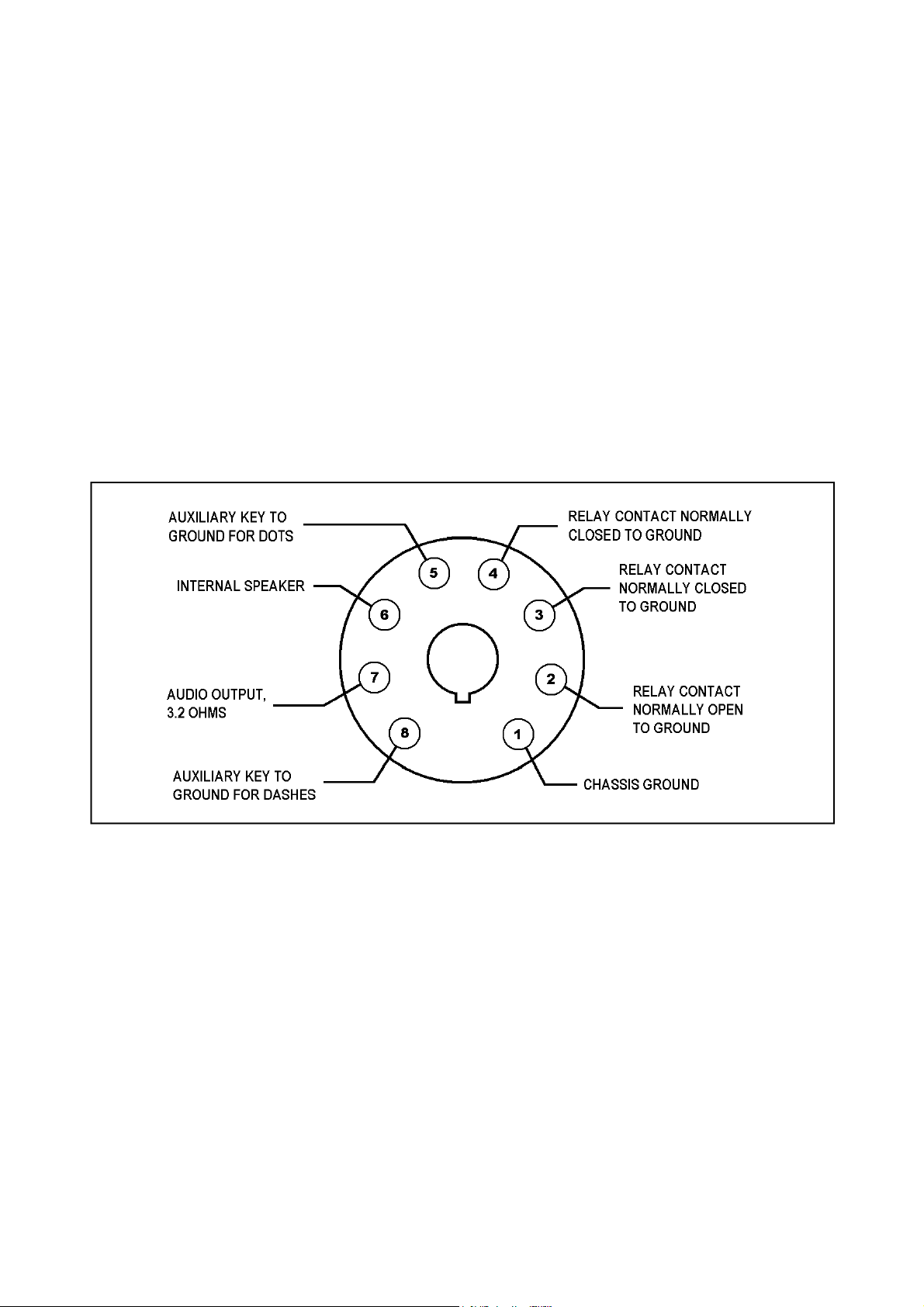
3-4-1. CONTROL OUTLET (See figure 3)
An eight-pin socket is provided to connect the Model HA-1 keying unit into
the station control system. The mating connector for this socket is an Amphenol
type CP-8 (one is supplied).
3-4-1-1.AUXILIARY KEY LEVER CONNECTIONS (Pin 1, 5 and 8)
At the user's option, the key lever may be connected to the control outlet
instead of to the panel key jack. Pin 1 is chassis ground, pin 5 is switched to
ground for dots, and pin 8 is switched to ground for dashes.
Figure 3. Control Outlet Connections.
Page 6
3-4-1-2.KEYING CONTACTS (Pin 2, 3 and 4)
Pin 2 (normally open to ground) is normally used for transmitter keying
purposes.
Pin 3 and 4 (independent, normally closed to ground) are provided for
auxiliary control of station facilities.
IMPORTANT
The mercury-wetted relay contact rating is 5 amperes maximum, or 500
volts maximum, the product not to exceed 250 voltamperes with contact
protection. For example, the maximum allowable voltage with a 5-
ampere load is 50 volts ( 5 A × 50 V = 250 VA); the maximum allowable
current with a 500-volt supply is 0.5 ampere (500 V × 0.5 A = 250 VA).
Refer to paragraph 3-5 for method of determining required contact
protection network.
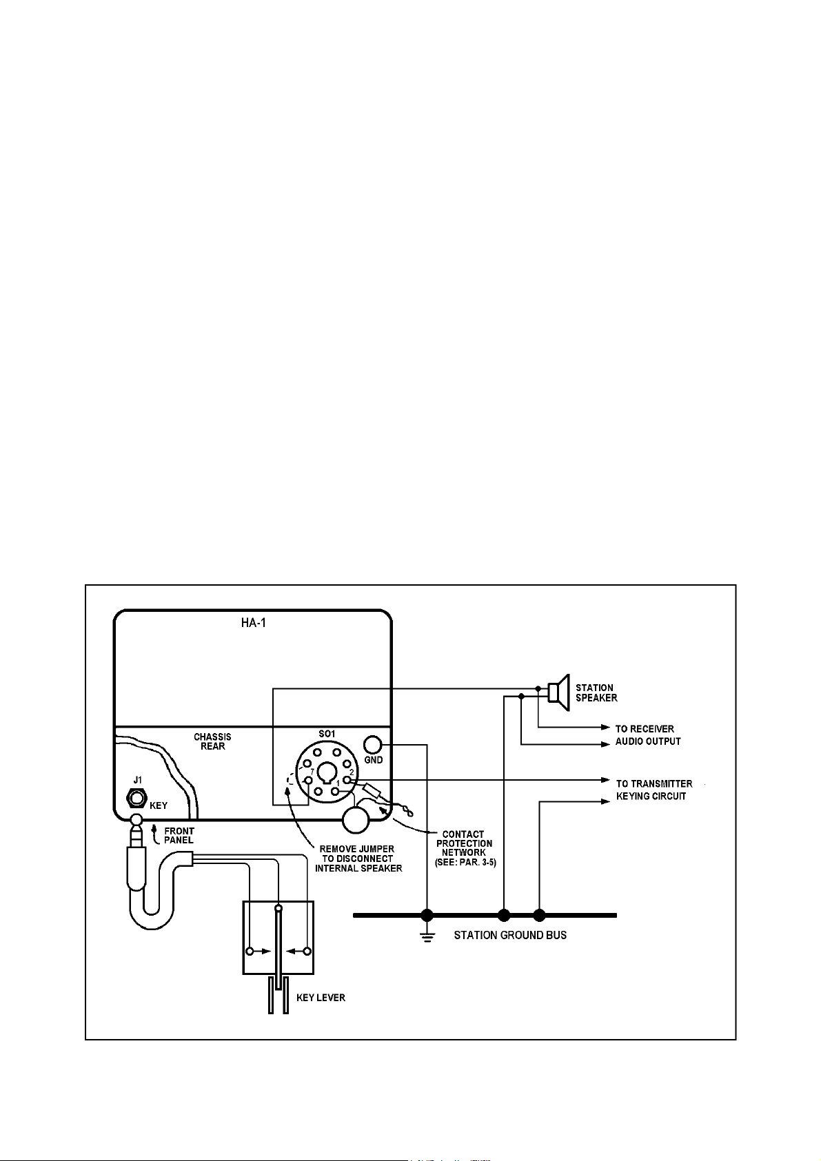
3-4-1-3.Speaker (Pin 6) AND AUDIO OUTPUT (Pin 7)
A standard circuit transfer type PHONES jack (J1) on the rear apron
automatically disconnects the internal speaker when the phone plug is inserted.
Output impedance is 3.2 ohms, although it is suitable for use with any low or
medium impedance headsets.
Figure 4. Typical Station Installation.
Page 7

3-4-3. GROUNDING POST
The ground post, provided at the rear of the keyer, should be utilized to
establish a ground for this unit.
IMPORTANT
It is recommended that the unit permanently connected to the
station grounding system so as to prevent the possibility of a
shock hazard developing as a result of component failure.
3-5. RELAY CONTACT PROTECTION NETWORK
Except for very light loads (under 2 mA and 50 V), the relay must be
provided with a contact protection network consisting of a capacitor and resistor
in series. This network is shown in the lower right-hand corner of the chassis in
figure 4. The network prevents possible arcing which would eventually destroy
the contacts. The voltage and current requirements of the circuit to be keyed
should be determined, and the relay contacts provided with an appropriate
protection network prior to the connection into the circuit.
The chart (figure 5) affords a convenient means of determining the necessary
contact protection.
Hallicrafters Model HT-30, HT-32, HT-32A, HT-32B, HT-37, HT-44, SR-150
and SR-160 Transmitters require no protection network when used with this
keyer.
For the most effective protection, the network, as determined from the chart,
should be installed as close to the relay contacts as is possible. It is desirable to
install the network internally, directly at the relay socket; however, adequate
protection will be provided by installing the network at the network at the control
outlet.
To determine the proper protection network required for loads exceeding 2
mA or 50 volts, proceed as follows:
(1) Measure load current of circuit to be keyed with a suitable ammeter.
(2) Measure open circuit load voltage at the keying points.
(3) To find C, read directly up from the value of load current on the
horizontal scale to its intersection with the sloping capacity line; the
value of C is determined from the right hand scale.
To find R, read directly up from the load current value to its
intersection with the appropriate load voltage line; the value of R is
read from the left-hand scale.
Page 8

Example I: A circuit maintaining a load current of 2.0 amperes and
an open circuit load voltage of 100 volts would require a C value of
0.4 µF and an R value of approximately 3.6 ohms. (See dotted lines
on chart).
Example II: Measured current and voltage is 50 mA and 150 V
respectively.
Solution: The proper protecting network would be a 0.001 µF
capacitor (Limiting capacity) in series with a 750 ohm resistor.
In current and voltage applications beyond the scope of the chart, the
minimum limiting capacitance value of 0.001 µF and a maximum resistance
value of 10,000 ohms should be used in the protection network.
Page 9

Figure 5. Relay Contact Protection Chart.
Page 10

SECTION IV
FUNCTIONS OF OPERATING CONTROLS
4-1. FUNCTION SWITCH
The FUNCTION control is a four-position rotary switch: (1) turns the unit ON
and OFF, (2) selects low or high speed operation, and (3) has a center HOLD
position for transmitter tuning purposes (key down).
4-2. SPEED CONTROL
The SPEED control provides a means of adjusting the keying speed between
10 and 30 WPM when the FUNCTION switch is in the LOW position or between
25 and 65 WPM in the HIGH position.
4-3. SIDETONE CONTROL
The SIDETONE control (knurled shaft), accessible at the rear of the unit,
adjusts the amplitude of the keyed monitor tone.
4-4. BALANCE CONTROL
The BALANCE control (screwdriver slot shaft), mounted at the rear of the
unit, differentially adjusts the gain of tube V3 to compensate for tube section
differences and aging. The adjustment should remain fixed for long periods of
time and need only be readjusted when V3 is replaced or when major service has
been performed.
To adjust the BALANCE control proceed as follows
(1) Turn the control to its maximum counterclockwise position. The unit
will key a continuous dash. Advance the control in the clockwise
direction, and note the point at which the dash stops.
(2) Turn the control to its maximum clockwise position and close the key
to dash. The unit will key a continuous series of dots as long as the
key is held closed to dash. Adjust the control counterclockwise to the
point where self-completing dashes are formed. Note this setting.
(3) Set the control midway between the points noted in step 1 and 2
above. The BALANCE control is now properly set and should require
no further attention.
Page 11

4-5. WEIGHT CONTROL
The WEIGHT control (knurled shaft), located on the rear panel, and referred
to as the mark-space ratio adjustment, sets the time relationship of a dot (or
mark) to its following space. For normal CW work this is usually set for a ratio of
1 to 1. Other ratios can be obtained to accommodate various transmitter keying
characteristics or to suit personal preference (see figure 6).
To adjust the WEIGHT control, proceed as follows:
(1) Turn the control to its maximum counterclockwise position; the unit
will key a long mark with a short space.
(2) Turn the control to its maximum clockwise position; the unit will key
a short mark with a long space.
Figure 6. Dot-Dash-Space Relationship With Various Weight Control Settings.
Page 12

The effect of the adjustment on keying characteristics is especially evident
when listening to the keyed monitor signal with the unit running at its highest
speed.
To set the WEIGHT adjustment for a 1 to 1 ratio at the relay terminals, proceed as follows:
(1) Disconnect the keying leads from the transmitter and reconnect the
leads to an ohmmeter. Set the ohmmeter to its lowest range.
(2) key a continuous series of dots at a fairly high speed (approximately
45 WPM).
(3) Adjust the WEIGHT control for a half-scale ohmmeter deflection.
Connecting an oscilloscope to the output of the transmitter so that the keyed
output may be seen is a more accurate means of setting the desired ratio. This
permits adjustment of the overall keying characteristic of the station although the
method mentioned earlier, will generally suffice for most systems.
SECTION V
OPERATION
5-1. GENERAL
Rapid effortless operation of the keyer requires a certain "knack" that comes
only with practice. Habits acquired by the use of conventional keys will have to be
overcome before the full capabilities of the keyer can be realized.
Care should be exercised in the selection of a key lever for use with the
Model HA-1 keying unit; one incorporating good mechanical construction,
particularly at the pivot and contact points, is a desirable and will provide long
reliable service.
Manufacturer's recommendations as to the keyer lever's adjustment should
be closely followed for optimum performance. It is desirable to adjust the dotdash contacts for the shortest possible excursion that will result in reliable makebreak action. Key lever contacts should be periodically inspected to prevent the
build-up of dirt and oxidation which can cause erratic keying.
5-2. OPERATING CHARACTERISTICS
The neon indicator on the front panel serves two functions: (1) it indicates
that the power is on and the unit ready for use, and (2) it serves as a visual
keying monitor. It will be noted that the indicator flashes once for each dot
Page 13

formed and twice for each dash. In a perfectly formed character the rhythm of the
Patent Application Pending
flashes will be uninterrupted.
SECTION VI
THEORY OF OPERATION
6-1. GENERAL
The keyer forms dots and dashes by the use of digital circuitry and logical
sequencing. Basic speed and mark-space ratios are established by a keyed multivibrator that operates continuously as dots and dashes are keyed to form a letter.
Dashes are formed by adding the output of this time base (dot) generator with the
output from a scale-of-two circuit. So formed, the dashes are always at the
correct speed and mark-space ratios, as illustrated by figure 6.
6-2. CIRCUIT DESCRIPTION AND OPERATION
1
Tube V1 is an astable (free-running) multivibrator which is keyed by series
triode tube V2A. Positive feedback from V1A plate through resistor R16 holds V2A
conducting after a momentary contact of the key lever to produce self completing
dots. The dots are uniform whether momentarily initiated or fully keyed, as in a
series. Speed is controlled by positive grid bias adjustment potentiometer R9.
Speed range is determined by the selection of grid return resistors R1 and R6, or
R2 and R7. Mark-space ratio is adjusted by differential grid resistor R8, with no
effect upon speed.
Tube V3 is a triggered bistable multivibrator, or a scale-of-two circuit. When
keyed by series triode tube V2B, it may be triggered by a negative pulse formed at
the start of a dot from the plate of V1B. When so triggered, the plate of V3B will
flip and remain positive until another negative pulse is received. Operating in this
manner, it forms half-speed dots which are added to the output of V1 and drive
the relay tube V4A to form perfect dashes.
1
Page 14

Figure 7. Model HA-1 Rear Oblique View.
Figure 8. Model HA-1 Bottom Chassis View.
Page 15

The sidetone signal is produced by a neon-type relaxation audio oscillator,
amplified by V4B, and keyed by the relay. Frequency of the tone is determined by
resistor R27 and capacitor C8. The sidetone level is controlled by potentiometer
R28.
The power supply incorporates an electrostatically shielded transformer to
minimize possible RF pickup and to provide complete isolation from the power
line. Silicon rectifiers are used, and tubes V5 and V6 provide complete voltage
regulation.
The self-completing dot is formed in the following manner:
(1) The key lever contact closes momentarily.
(2) With grid bias removed, tube V2A conducts.
(3) Multivibrator V1 operates; V1A plate flips positive and trough R16
keeps V2A conducting to form a self-completing dot.
(4) The output from the plate of V1A is applied through R15 to the grid of
triode V4A which conducts and energizes relay K1.
The self-completing dash is formed as follows:
(5) The key lever dash contact closes momentarily.
(6) Tube V2B conducts to "arm" V3 for triggering.
(7) At the same time, diode CR1 conducts to start a self-completing dot,
as described in step 1 trough 4 above.
(8) The leading edge of the negative-going dot from V1B plate through
differentiator C3 and R12 forms a negative pulse to trigger V3.
(9) The plate of V3B flips positive, keying V1 through CR1, until the
leading edge of the second dot provides another negative pulse to flip
it negative.
(10) The second dot, already initiated, goes through completion to end the
dash cycle.
(11) The plate of V1A through R15, and the plate of V3B trough R14, drive
the grid of V4A positive; V4A conducts and relay K1 energizes for a
self-completing dash.
Page 16

SECTION VII
SERVICE DATA
7-1. CHASSIS REMOVAL
The chassis and front panel assembly can be easily withdraw from the
cabinet after the four screws on the bottom of the cabinet have been removed.
7-2. TUBE AND NEON LAMP REPLACEMENT
Complete access to all tubes can be obtained b removing the chassis from
the cabinet (see paragraph 7-1). The neon lamp is accessible from the front of the
cabinet.
7-3. TROUBLESHOOTING
Throughout the design of the Model HA-1 keying unit, full consideration was
given to keep maintenance problems at an absolute minimum. However, if a
malfunction does occur, the voltage chart and schematic diagram will aid in
isolating and correcting the malfunction. For the physical location of component
parts, refer to figures 7 and 8.
NOTE
The mercury-wetted relay will operate if inclined 30° or more
from the horizontal plane.
7-4. Model HA-1 TUBE SOCKET VOLTAGES
Tube 1 2 3 4 5 6 7 8 9
V1
V2
V3
V4
V5
V6
NOTES:
1. Measurements were made with a vacuum tube voltmeter connected
115
1
12
150
150
GND
between indicated tube socket terminal and chassis.
120
–17
0
–15
N.C.
N.C.
120
GND
GND
GND
N.C.
N.C.
GND
GND
GND
GND
N.C.
N.C,
H
H
H
H
N.C.
N.C.
21
120
105
150
N.C.
N.C.
0
–10
–12
0
GND
–108
GND
GND
1
4
- -
- -
N.C.
N.C.
N.C.
N.C.
- -
- -
2. Measurements were made with the FUNCTION switch in the LOW position; SPEED control maximum clockwise; BALANCE and WEIGHT
Page 17

controls at the center of rotation; and SIDETONE maximum
counterclockwise.
3. Indicated voltages may vary ±20 %.
7-5. SERVICE AND OPERATING QUESTIONS
For further information regarding operation or servicing of this equipment
contact the dealer from whom the unit was purchased. The Hallicrafters
Company maintains an extensive system of Authorized Service Centers where any
required service will be performed promptly and efficiently at no charge if this
equipment is delivered to the service center within 90 days from the date of
purchase by the original buyer and the defect falls
within the terms of the warranty. It is necessary to
present the Bill-of-Sale in order to establish warranty
status. After expiration of the warranty, repairs will
be made for a nominal charge. All Hallicrafters
Authorized Service Centers display the sign shown at
right. For location of the one nearest you, consult
your dealer or your local telephone directory.
Make no service shipments to the factory unless instructed to do so by letter,
as The Hallicrafters Company will not accept responsibility for unauthorized
shipments.
The Hallicrafters Company reserves the privilege of making revisions in
current production of equipment and assumes no obligation to incorporate such
revisions in earlier models.
Page 18

Page 19

 Loading...