

Halkey-Roberts Pro 1F® V95000
Service Instructions
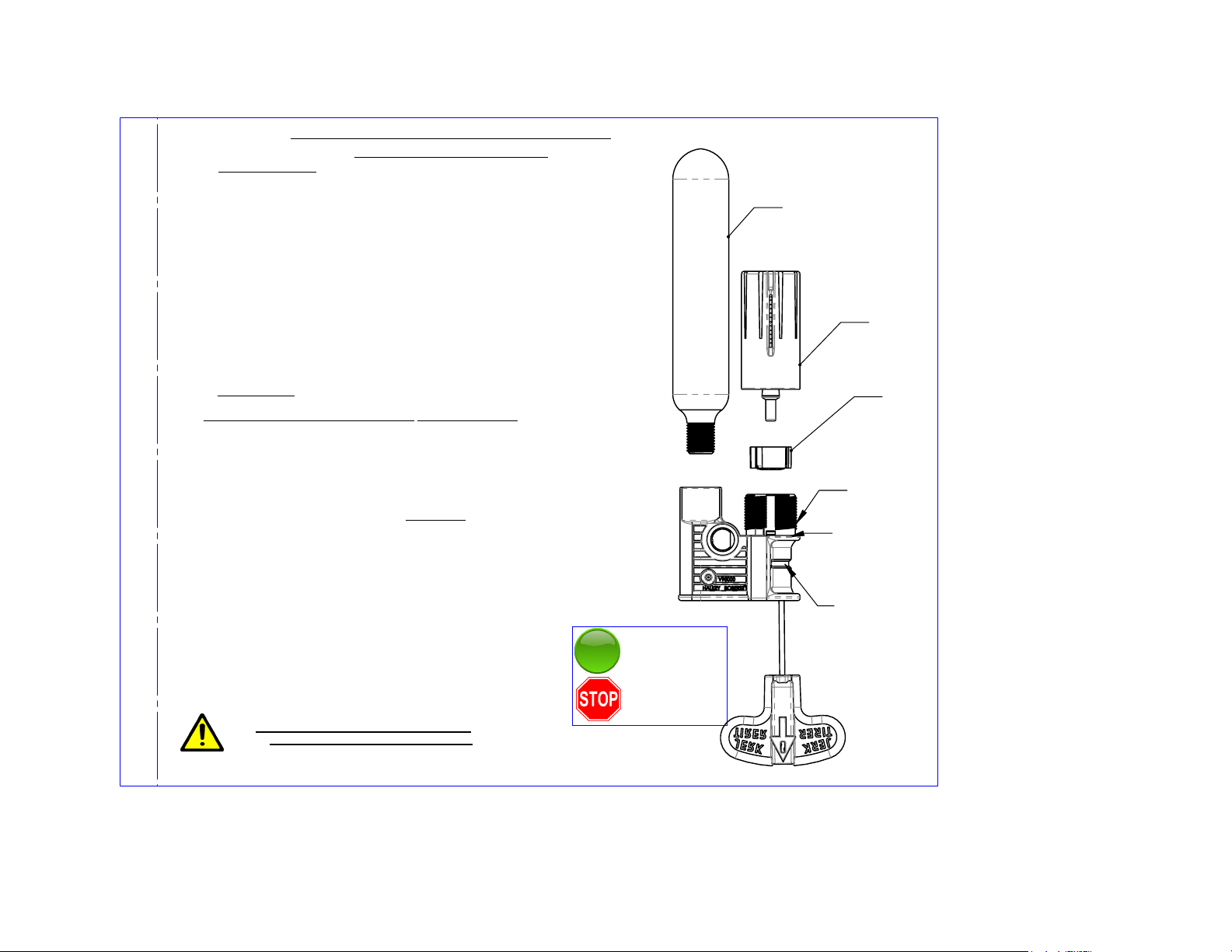
DISASSEMBLY
(see figure)
Step 1
: Unpack or open the life vest so that the manual/automatic inflator
is visible.
Step 2
: Remove gas CO2 cylinder by rotating cylinder couterclockwise then
pull out.
Step 3
Step 4
(yellow). Check the housing to be sure it is clear and dry.
Note: The bobbin (yellow) body may remain in the housing or in the cap
assembly when you remove the cap. The bobbin body must be removed prior
to Rearming.
Step 5
purchased
within three ( 3 ) years. If bobbin purchase date is unknown, check date on
bobbin, replace if over three (3) years.
Step 6
Bobbin (yellow) must be installed into the
side up, aligning the slots on the bobbin with the ridges inside the threaded
housing. The bobbin will slide in easily if installed correctly.
Step 7
shoulder.
Note: No gap between the cap and the housing shoulder.
Step 8
Install the bobbin and cap before installing a new cylinder.
Step 9
inflator threads. Turn cylinder clockwise till a firm seal is achieved.
Step 10
Discard cylinder.
: Remove cap by turning counter-clockwise.
: Remove bobbin from cap or housing unit.
REARMING
Note: Rearming must follow the sequence below
: A new bobbin must be used. New bobbin must have been
:
: Install cap by screwing clockwise until it meets the housing
: Check the new cylinder to be sure it has not been punctured.
: Install new cylinder by engaging the cylinder threads with the
: Check to be sure service indicator is
IMPORTANT
IMPORTANT
WARNING: PFD WILL ONLY INFLATE IF
CYLINDER IS TURNED TO FULL STOP.
!
HOUSING
!
Discard bobbin
.
(**see figure), white
GREEN.
SERVICE INDICATOR
If green, unit is
operable.
If red, stop and
service unit.
C02 CYLINDER
STEP 2.
CAP
STEP 3.
BOBBIN
STEP 4.
HOUSING
STEP 6.
HOUSING
SHOULDER
STEP 7.
SERVICE
INDICATOR
STEP 10.

Halkey-Roberts Pro 1F® V95000
Démontage
Étape 1
: Ouvrez le gilet de sauvetage de sorte que le compresseur
manuel/automatique
soit visible.
Étape 2
antihoraire.
Jetez ensuite le cylindre.
Étape 3
Étape 4
Vérifiez
le boîtier pour vous assurer qu’il est propre et sec.
Remarque : Le corps de la bobine (jaune) peut rester dans le boîtier ou dans
l’assemblage du capuchon lorsque vous retirez le bouchon. Le corps de la bobine
doit
être retiré avant le montage.
Étape 5
bobine ne
doit pas avoir plus de trois (3) ans. Si vous ne connaissez pas la date d’achat de la
bobine, vérifiez la date inscrite sur celle-ci. Si la bobine a plus de trois (3) ans,
remplacez-là.
Étape 6
La bobine (jaune) doit être installée dans le Boîtier (**voir la figure), le côté
blanc vers
le haut et dirigée vers le capuchon, en alignant les fentes sur la bobine avec les
cannelures à l’intérieur du boîtier fileté. La bobine glissera à l’intérieur
facilement si
elle est installée correctement.
Étape 7
touche
la surface du boîtier.
Remarque : Aucun espace n’est toléré.
Étape 8
IMPORTANT!
Installez la bobine et le capuchon avant d’installer un nouveau cylindre.
Étape 9
compresseur. Tournez le cylindre dans le sens horaire jusqu’à obtenir un joint
solide.
Étape 10
: Retirez le cylindre de CO2 en le dévissant fermement dans le sens
: Enlevez le capuchon en le dévissant dans le sens antihoraire.
: Retirez la bobine du bouchon ou du boîtier. Jetez la bobine (jaune).
Réarmement
Remarque : Le réarmement doit suivre la séquence ci-dessous.
: Vérifiez la date sur la bobine dans l’ensemble de réarmement. La
: IMPORTANT!
: Installez le bouchon en le vissant dans le sens horaire jusqu’à ce qu’il
: Vérifiez le cylindre pour vous assurer que celui-ci n’est pas perforé.
: Installez le nouveau cylindre en engageant les filets avec ceux du
UNIQUEMENT SI LE CYLINDRE EST TOURNÉ
JUSQU’À L’ARRÊT COMPLET.
: Vérifiez que l’indicateur de service est
(voir la figure)
AVERTISSEMENT : L’UNITÉ PFD SE GONFLE
Instructions d'Entretien
vert.
INDICATEUR DE SERVICE
Si l’indicateur est vert,
l’unité est exploitable.
Si l’indicateur est
rouge, arrêtez et
réparez l’unité.
Cylindre de C02
Étape 2.
Capuchon
Étape 3.
Bobine
Étape 4
Bo
Etape 6.
Surface
du Bo
Étape 7.
Indicator
de service
Étape 10.
Î
tier
Î
tier
 Loading...