

Page 1
wireless computer
owner’s manual
80mm x 110mm
Black
Page 2

2
Contents
Package Contents ....................................... 3
Using Your Computer ...................................
4
1.Main Unit Setup ........................................................ 4
1. Initiation of Main Unit
2. Basic Display Modes
2. Overview of Button Operation............................... 5
1. In Data Setting Mode
2. In General Mode
3. In Altitude Calibration Mode
3. Wheel Circumference Measurement .................. 8
4. Basic Setting & Operation ...................................10
5. General Display .....................................................14
6. Battery Replacement ............................................15
7. General Mode Display ..........................................16
8. About Altitude Calibration ...................................17
9. Temperature Display ............................................18
10. Bike 1 /Bike 2 Selection ......................................18
11. Data Reset ............................................................19
12. EL Backlight .........................................................20
13. Sleep Mode ..........................................................20
Functions ..................................................... 21
Technical Specifi cation s ............................
27
General Specifications ................................
29
Precautions .................................................
30
Trouble Shoot ing ........................................
31
Page 3
3
Package Contents
1. MAIN UNIT
Main unit
3V battery (CR2032)
2. BRACKET SET
Bracket for handlebar or stem
Bracket base
Cable ties
3. SPEED TRANSMITTER SET
Speed transmitter
3V battery (CR2032)
Transmitter rubber pad
Cable ties
Magnet set
O-ring
4. CADENCE TRANSMITTER SET
Cadence transmitter
3V battery (CR2032)
Transmitter rubber pad
Cable ties
Magnet set
O-ring
1.The installation of the accessories is on the separate sheet.
2.The accessories or parts are s ubject to c hange wit ho ut pr ior
notice.
Page 4
4
Using Your Computer
1.Main Unit Setup
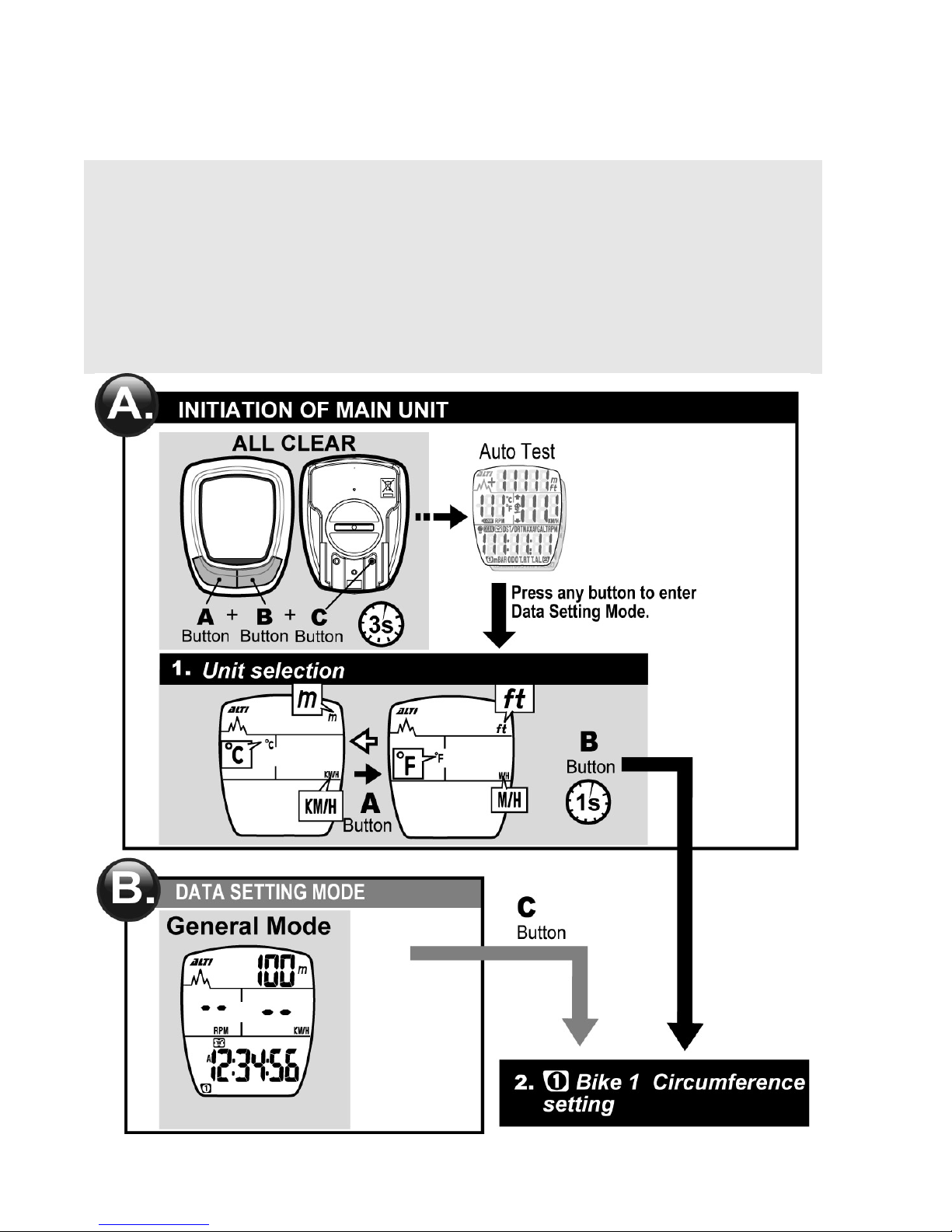
1. Initiation of Main Unit:
1. Before no rmal operation, in itiate the main unit and select units
as stated below:
1-1. Push buttons A, B, C simultaneously for 3 seconds, and
you'll see the auto-testing display.
1-2. Press any button to quit auto-testing display, and then
select units of temperature, altitude and distance.
1-3. Press the C button to quit unit selection and enter
General Mode.
2. Timing to initiate the main unit and select units is as listed
below:
2-1. The first time when you use the computer
2-2. When the display becomes irregular due to improper use
2-3. Whenever you change the battery
2. Basic Display Modes:
After initiating the computer, selecting units, you should enter
Data Setting Mode to set some basic data like wheel
circumference and clock time etc. Then go to General Mode for
normal operation.
Before riding, you should enter Altitude Calibration Mode to
calibrate the current altitude value.
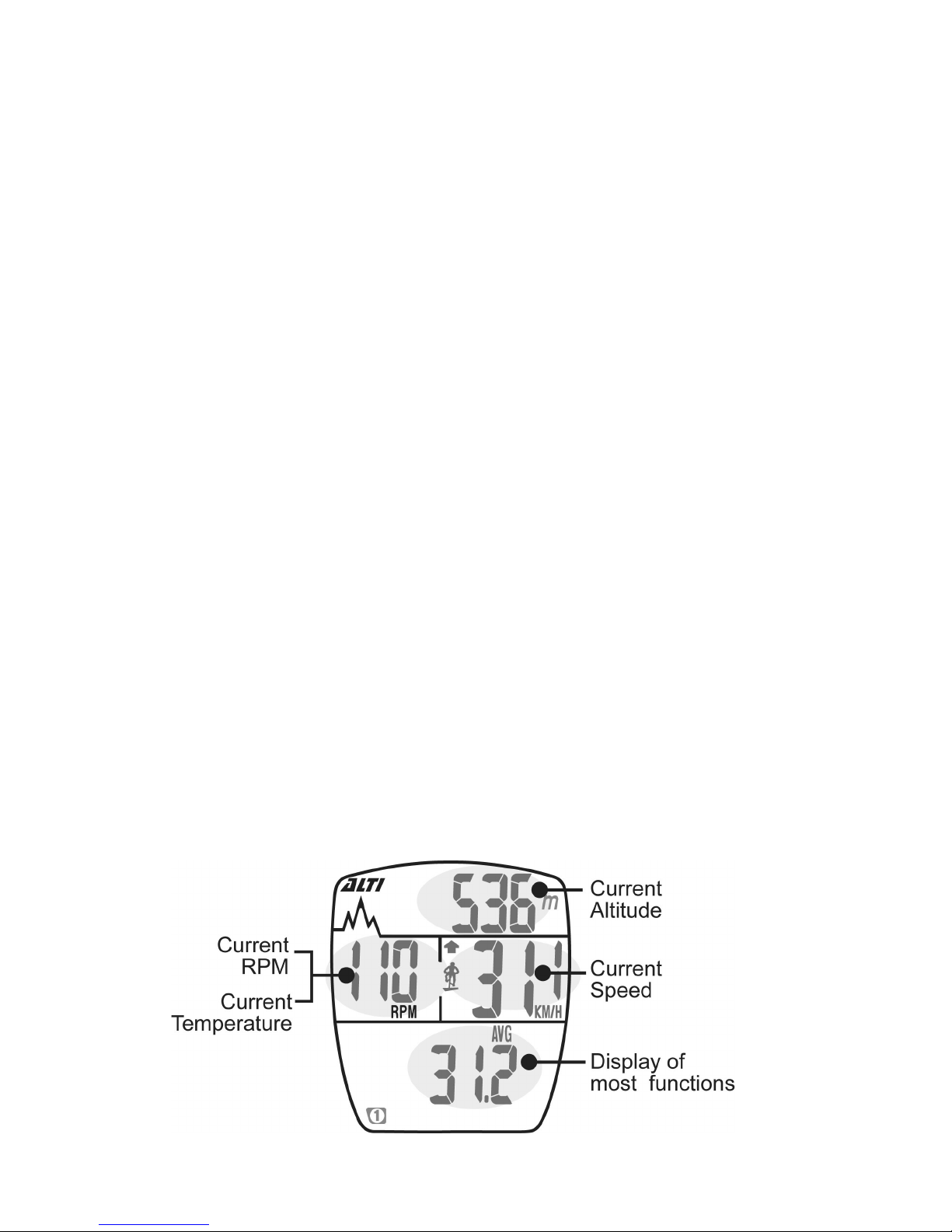
The following is the General Mode Display during riding for
reference:
Page 5
5
2. Overview of Button Operation
This computer includes three major display modes as shown below:
Data Setting Mode, General Mode, and Altitude Calibration Mode.
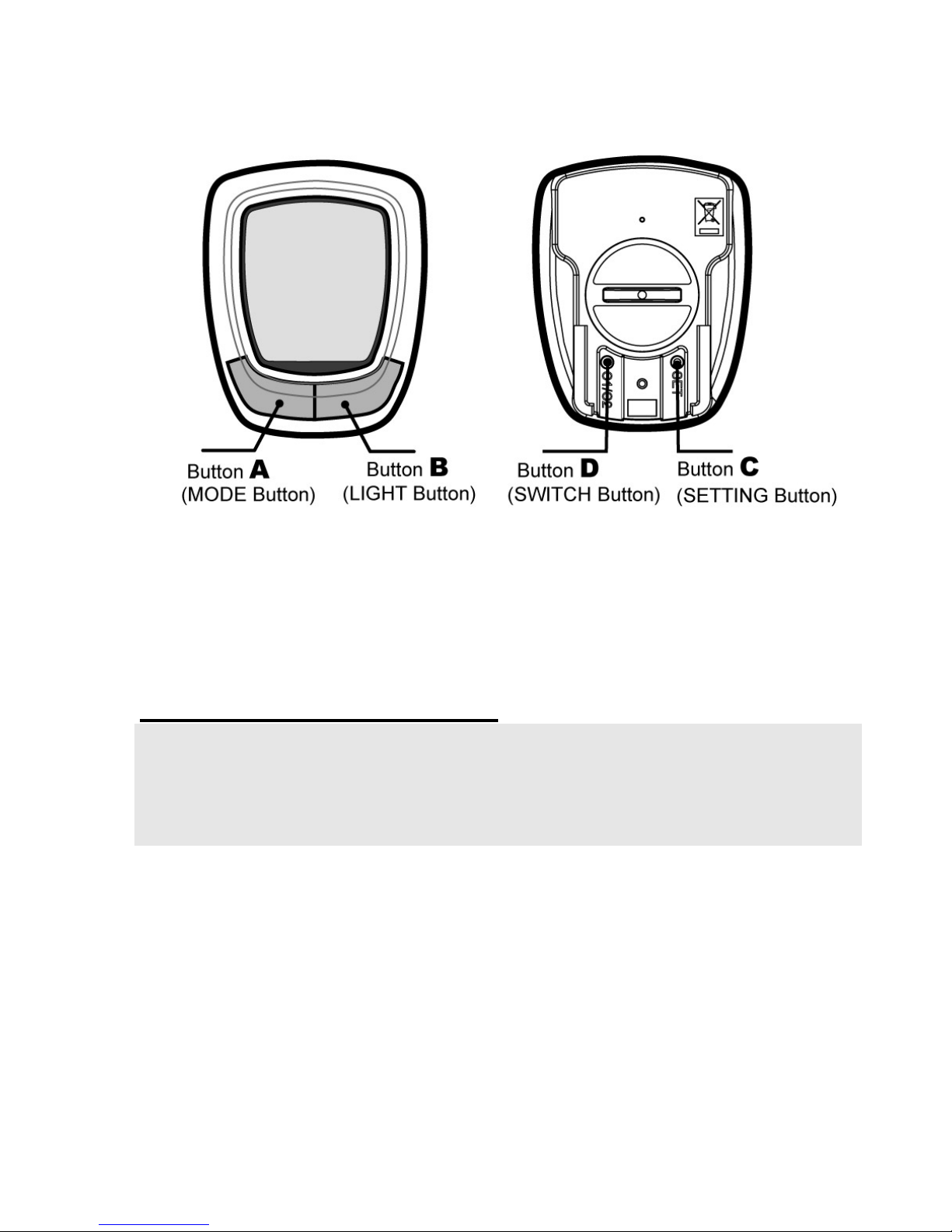
In this section, you'll learn the function of each button in each mode.
The following text lets you know how to use the buttons to operate
the computer step by step.
1. In Data Setting Mode:
Tips: 1. The buttons you'll use in Data Setting Mode: A, B, C.
2. Button for entering or quitting Data Setting Mode: C
3. Butto n for ch an gi n g the v al u e o f a flic ker i n g di git: A
4. Button for switching to the next digit or setting: B
Butt on A:
1. Press the A button to change the value of a
flickering digit in a loop.
2. If you keep pushing the A button, the digit value will
automatically increase.
3.Release the A button when the required value of a
digit is displayed.
Butt on B: 1. Press the B button to move to the next digit in a
loop.
2. Push the B button for 1 second to move to the next
setting.
Page 6

6
Butt on C: 1. In General Mode, press the C button to enter Data
Setting Mode.
2.In Data Setting Mode, press the C button to exit and
return to General Mode.
Butt on D: No function.
How do you enter Data Setting Mode after initiating the computer?
After initiating the computer by pressing the A, B, C buttons at the same
time for 3 seconds , pr es s any button to quit auto-testing display, and
then select units. After unit selection, press the B button for 2 sec onds
to enter Dat a S et ti n g M ode.
2. In General Mode:
Tips:
1. The buttons you'll use in General Mode: A, B, C, D
2. Button for changing the function display: A
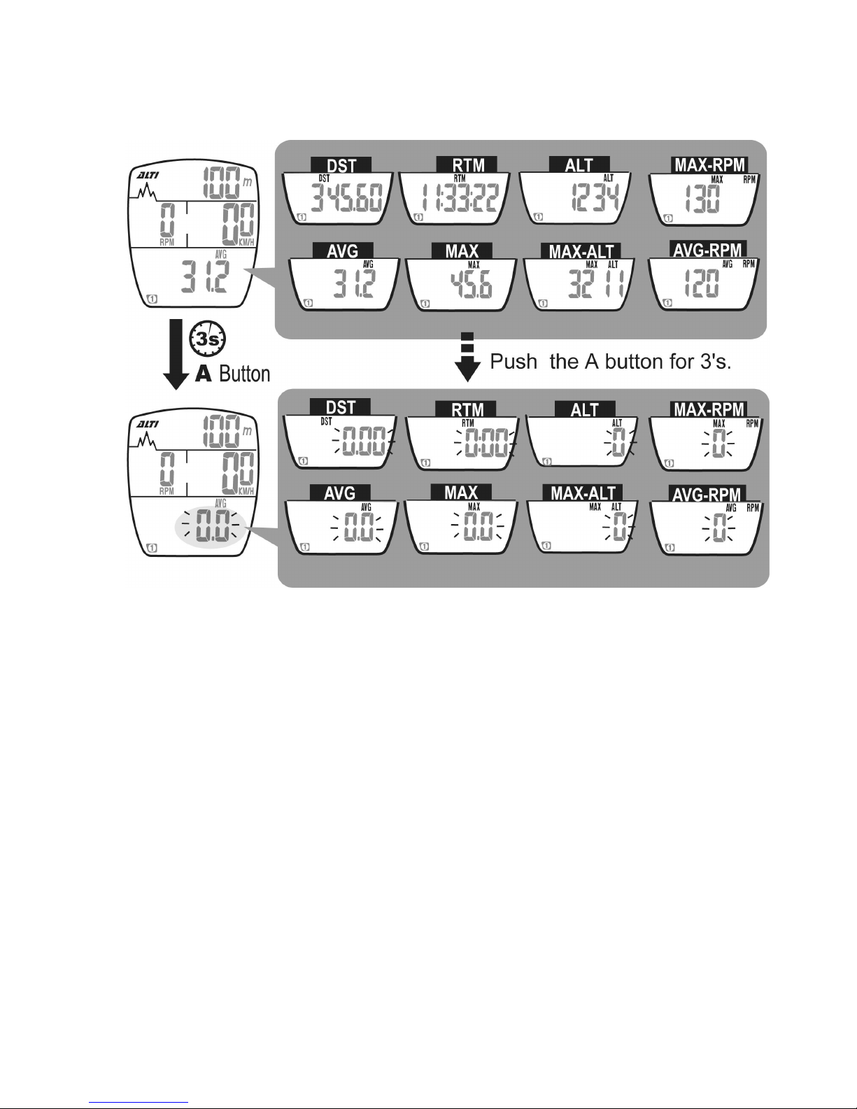
3. Button for resetting the trip data: A (3's)
4. Button for entering Data Setting Mode: C
5. Buttons for entering Altitude Calibration Mode: A+B (3's)
Butt on A:
1. Press the A button to move to the next function
display.
2. Press the A button for 3 seconds, and you will
reset the following data:
AVG SPD, MAX SPD, DST, RTM, ALT, MAX ALT,
AVG RPM, MAX RPM.
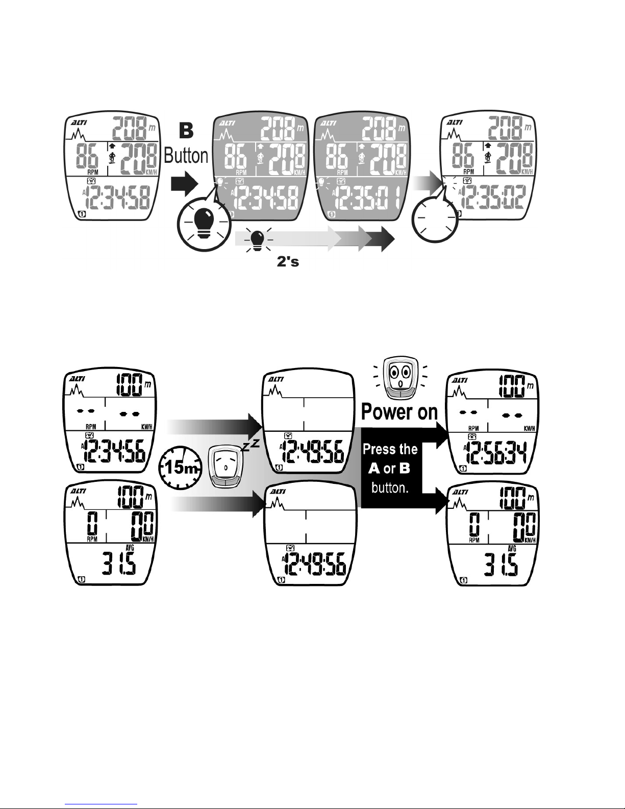
Butt on B: 1. Press the B button to turn on the EL backlight.
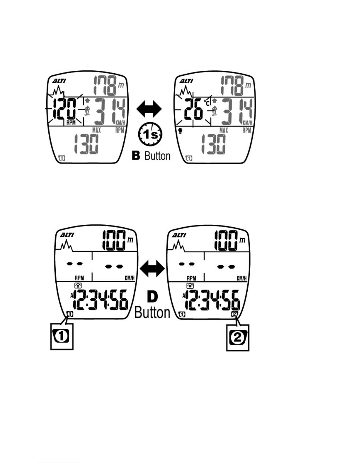
2. Press the B button for 1 second, and the
temperature will be displayed.
Butt on C:
Press the C button, and you'll enter Data Setting
Mode.
Buttons A+B: Push both buttons for 3 seconds, and you'll enter
Altitude Calibration Mode.
Butt on D:
Press the D button to switch to Bike 1 or Bike 2.
Page 7

7
3. In Altitude Calibration Mode:
Tips:
1.The buttons you'll use in Altitude Calibration Mode: A, B.
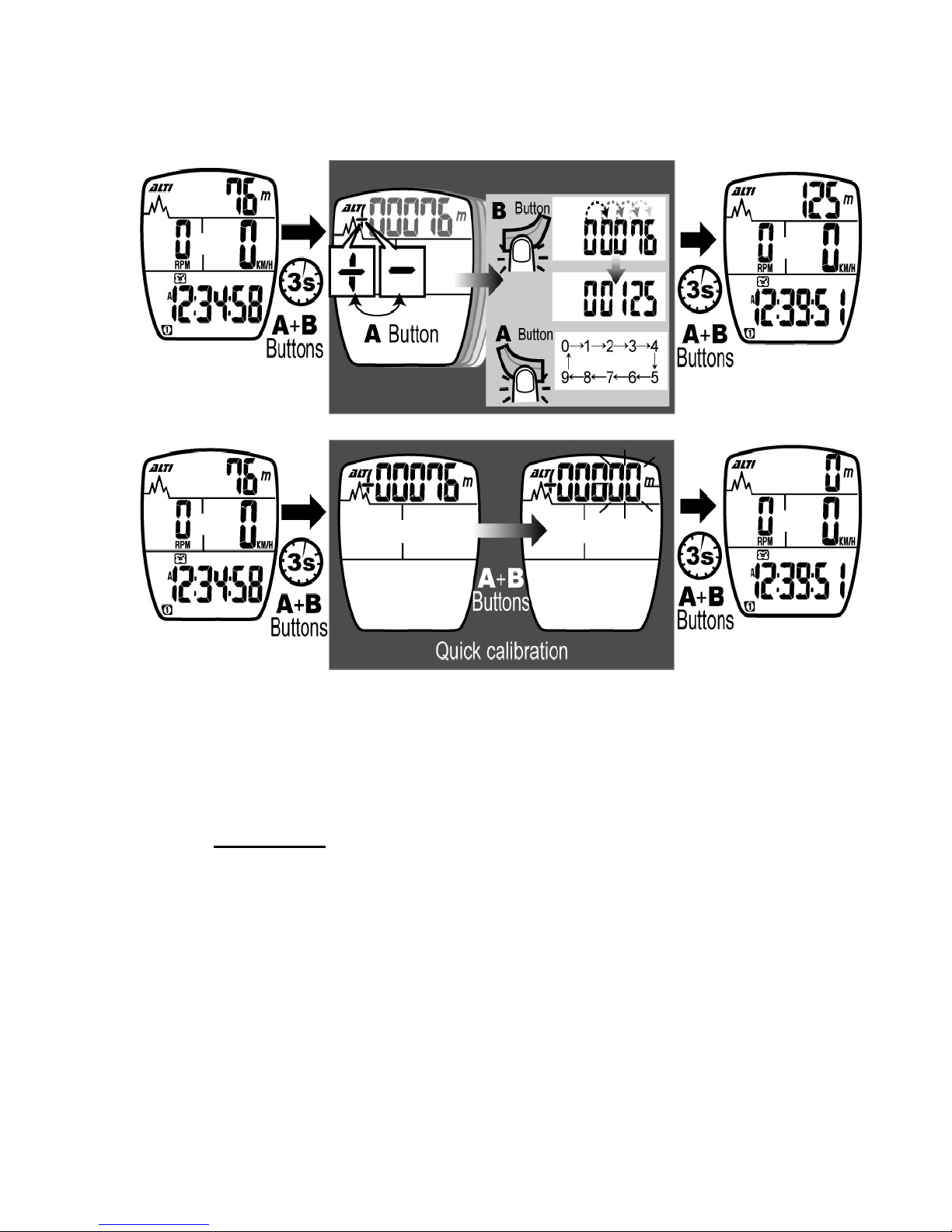
2.Buttons for enter i ng or qui tti ng Al ti tu de C al ibr at ion Mode: A+B ( 3's)
3.
Buttons for quickly resetting the current altitude to zero: A+B (1's)
Buttons A+B:
1. In General Mode, push A and B buttons for 3
seconds to enter Altitude Calibration Mode.
2. In this mode, press A and B buttons at the same
time briefly, and the current altitude value will
return to zero. It's convenient for quick setting.
3. Push A and B buttons for 3 seconds to quit this
mode and return to General Mode.
Butt on A:
1. Press the A button to change the plus sign to
minus, or change the minus sign to plus.
2. Press the A button to change the value of a
flickering digit during setting.
Butt on B:
Press the B button to move to the next digit in a
loop during setting.
About Altitude Calibration:
1. If you are aw are of your hom e altitude or basis alti tude before ri ding, you can
directly adj ust the c urrent altitude dat a after you enter t his m ode.
2. If you do not know your basi s al ti tude be fore ridi ng or if yo u do not c ar e
about the altitude of the starting point, you may return the current
altitude value to zero in the calibration mode by pressing both A and B
buttons at the same time briefly. In this way, the rider will still enjoy the
fun of learning the accumulated altit ud e gai n s dur i ng eac h ride.
Page 8
8
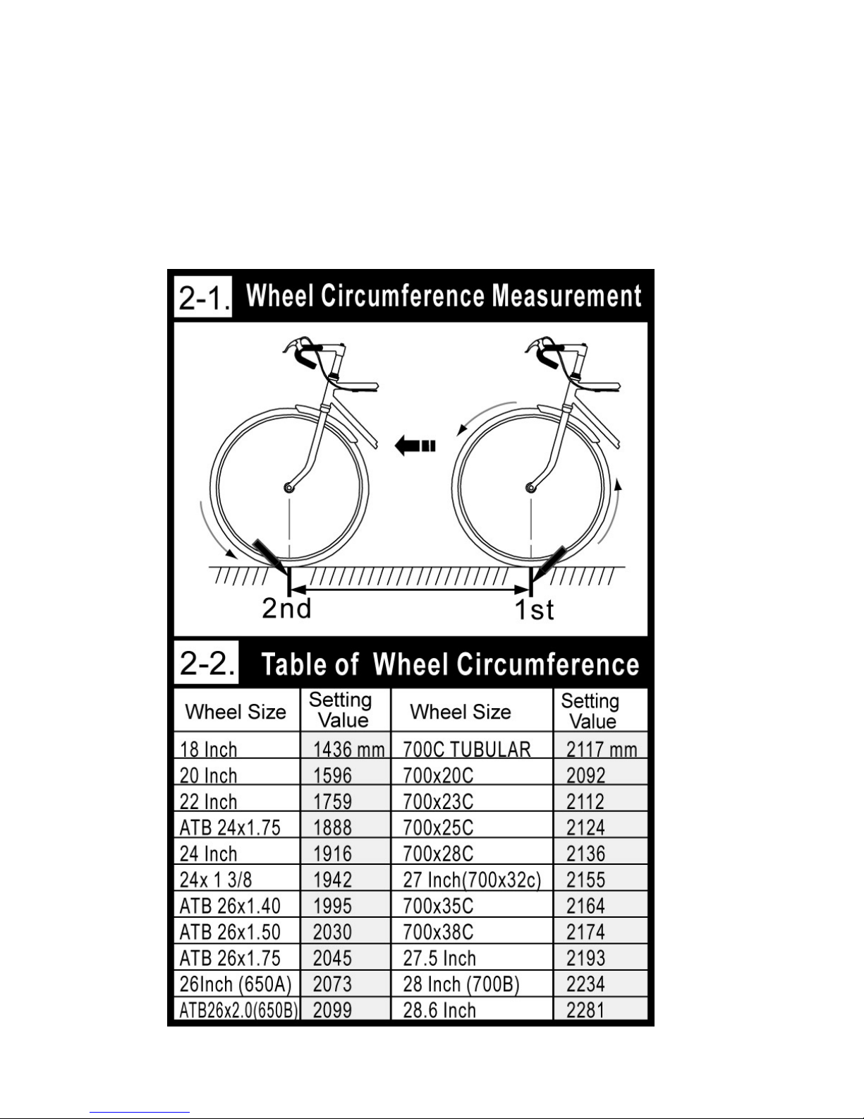
3. Wheel Circumfer en ce
Measurement
To set the wheel circumference before riding, you should
measure the wheel circumference by yourself or just refer to the
Wheel Circumference Table as shown below:
Page 9

9
How do you measure the wheel circumference
yourself?
Roll the wheel until the valve stem is closest to the ground and mark
the corresponding spot on the floor as the first point. Next, roll the
wheel forw ard until t he valv e stem is closes t to the grou nd onc e again .
Mark the corresponding spot on the floor as the second point.
Then measure the distance between both points, using the unit of
millimeter. The distance equals your wheel circumference.
1. The default value of wheel circumference for Bike 1 is 2155mm;
that for Bike 2 is 2050mm. Enter the correct wheel
circumference into the computer in Data Setting Mode.
2. Refer to pages 10 and 11 about basic setting to set your wheel
circumference.
Page 10
10
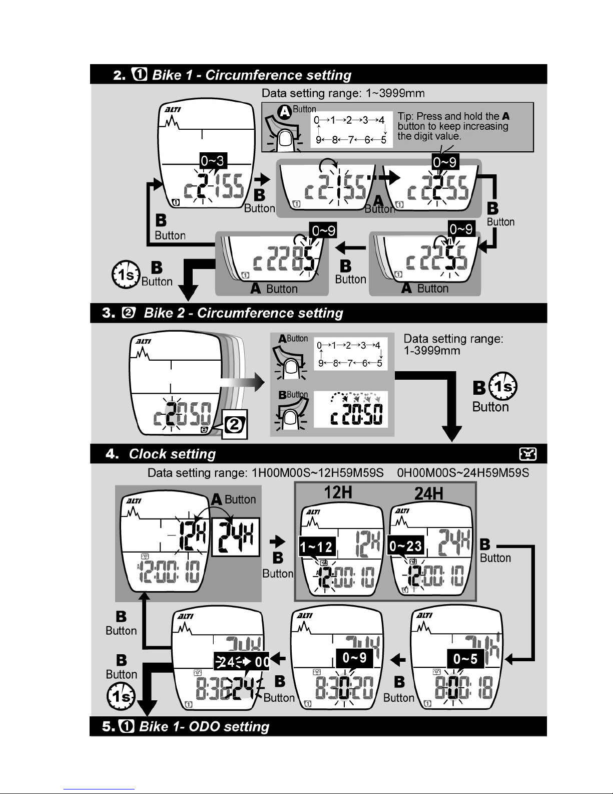
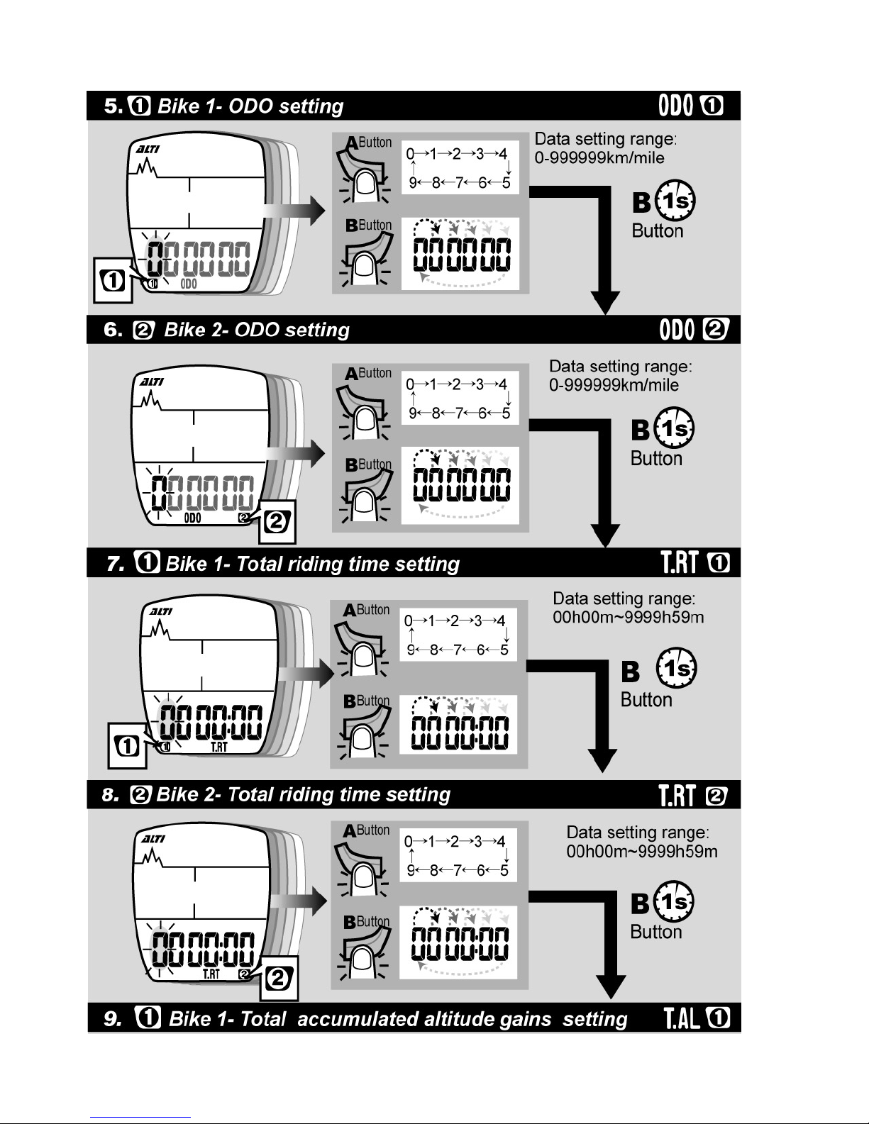
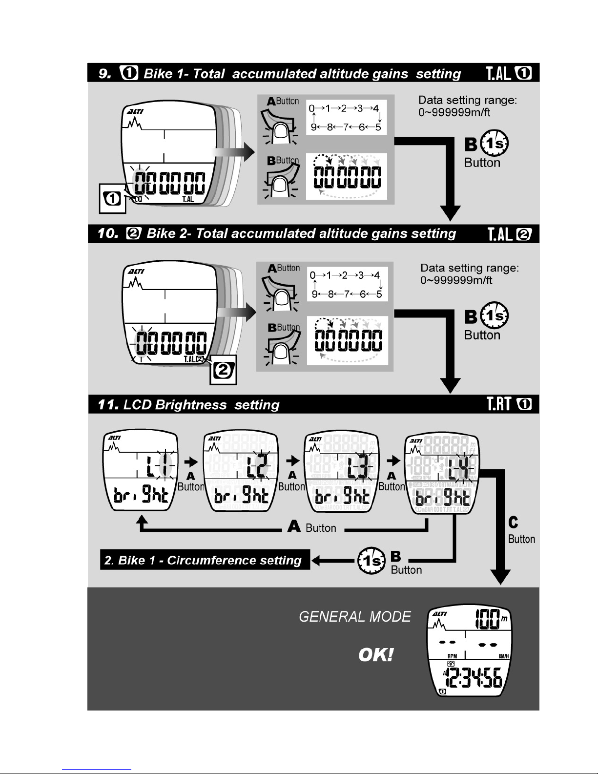
4. Basic Setting & Opera ti on
Tip for Data Setting :
1. Press the A button to change the value of a flickering digit.
Press the B button to move to the next digit in a loop.
2. Press a nd hold the B butt on for 1 s econd t o move to the next setting
when the current setting is finished.
3. If the computer is idle during Data Setting Mode for 20
seconds, it'll automatically return to General Mode.
Page 11
11
Page 12
12
Page 13
13
Page 14
14
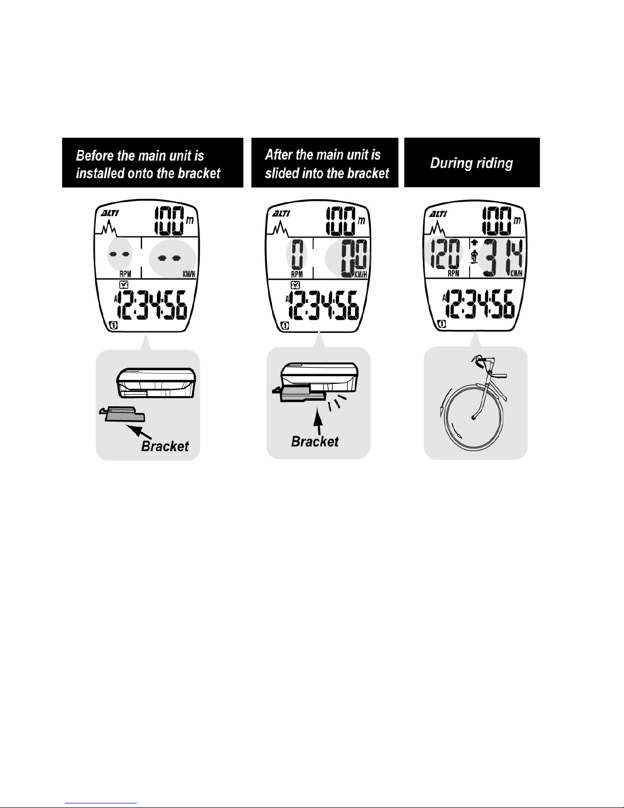
5. General Display
The display of General Mode looks different in different phrases as
shown below:
1. Put the main unit onto the bracket, and the main unit will
automatically start measuring the speed and cadence.
2. The main unit will automatically enter Sleep Mode in 15
minutes once it doesn't receive any signals from the bike.
3. Only current time is displayed when the computer is in Sleep
Mode (Power-Saving Mode.)
4. Press the A or B button to wake it up, and it'll show the
previous display and resume measuring.
5. When the main unit is on the bracket, you cannot enter Data
Setting Mode or switch between Bike 1 and Bike 2.
Page 15
15
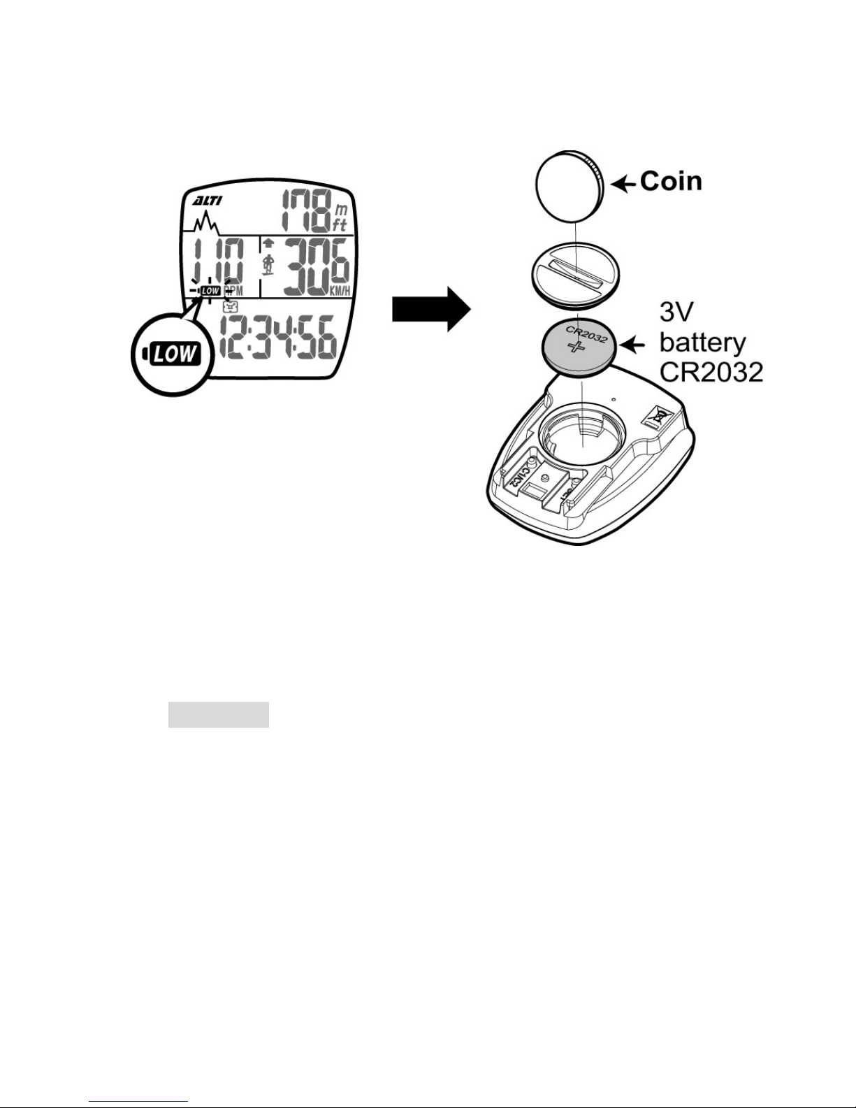
6. Battery Replacement
1. When the low battery indicator is shown on the display,
replace the battery with a new one A.S.A.P.
2. The positive (+) pole of the CR2032 battery must face the
battery cap.
3.Press buttons A, B, C for 3 seconds to initiate the main unit.
Attention: When there's the low battery symbol on the screen,
we suggest that you replace the battery w ith a new one A.S.A.P.
Otherwise, the altitude measurement result may be incorrect,
and the new data may be lost.
Page 16
16
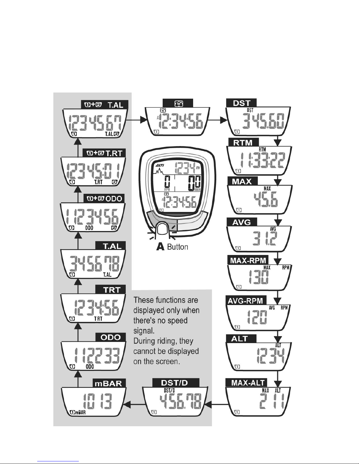
7. General Mode Display
When you are riding with the computer, some functions will not
be displayed on the screen. These functions like T.AL, ODO,
mBAR, DST/D are displayed only when you stop riding.
Page 17
17
8. About Altitude Calibration:
Tip for Quick Altitude Calibration
1. Press both A and B buttons for 1 second, and the current
altitude value will return to zero.
2. Press the A button to set the value of a digit, and press the B
button to move to the next digit.
3. Attention: Calibrate the current altitude only when
there're no speed signals.
Page 18
18
9. Temperat ure Display
10. Bike 1 /Bik e 2 Sel ection
Bike 1 and Bike 2 have their separate data in the computer.
Page 19
19
11. Data Reset
1. Press and hold the A button for 3 seconds to reset data of DST,
RTM, MAX, AVG, ALT,MAX-ALT, MAX-RP M, AVG -RPM
2. The following data are stored in memory and cannot be reset:
Unit, Cmm1 (Circu mference 1), Cmm2, ODO 1, ODO 2, T.RT1,
T.RT2, T.AL1, T.AL2.
3. Reset data for Bike 1 and data for Bike 2 respectively.
Page 20
20
12. EL Backlight
13. Sleep Mode
Press the A or B button to wake it up.
Page 21

21
Functions
The display of the computer can be divided into three sections –
upper, middle, and lower display.
In General Mode, the LCD display of your computer is as below:
The current altitude is always shown on the upper display, and it's
easy to calibrate it when necessary. Current speed and current
RPM are always shown on the middle display. And most functions
are shown on the lower display-- you may press the A button to
view each function display.
Regarding the functions marked with listed below, the data
can be reset to zero by the reset operation. (When in Ge ner al
Mode, press the A button for 3 seconds to reset the
computer.)
ALTI Current Altitude
1. The current altitude is always displayed on the upper display.
2. To get accurate basis altitude, the cyclist should calibrate the
altitude before each ride.
3. The measurement is based on the principle that atmospheric
pressure decreases as elevation increases.
4. The altitude is m eas ured by m eans of the atmospheric p ressur e,
so it's weather-dependent.
5. You may obtain the altitude data from a topographic map or the
Internet.
6. The altitude of the altimeter is pre-calibrated by the precise
instrument at the factory before shipment.
Current Speed
1. The current spee d is always show n on the middle display d ur ing
riding.
2. The speed data are updated per second.
3. For Bike 1, when you do not ride the bike for more than 4
seconds, the speed data will be reset to zero.
For Bike 2, when you do not ride the bike for more than 2
seconds, the speed data will be reset to zero.
Page 22

22
MAX Max. Speed
1. With this function, the computer will record the maximum speed
you reach during riding.
2. Whenever you reset the computer or change the battery, the
max. speed record will be cleared.
AVG Average Speed
1. With this function, the computer will display your average speed
during riding.
2. Whenever you reset the computer or change the battery, the
average speed record will be cleared.
3. It'll display "0.0" if the riding time is below 6 seconds.
4. It's updated every second on condition that the riding time is
over 6 seconds.
5. The computer will automatically reset the following data to zero
once the RTM is over 100 hours or the DST is over 1000KM (or
miles):
RTM (riding time), DST (trip distance), AVG (average speed.)
DST Trip Distance
1. DST refers to the accumulated distance during a trip.
2. Whenever you res et t h e computer or change the batte ry, the tr ip
distance record will be cleared.
RTM Riding Time
1. RTM refers to the accumulated riding time of a trip.
2. Whenever you res et the computer or chang e t he batte ry, the t ri p
distance record will be cleared.
3.The computer automatically starts measuring the riding time
upon receipt of wheel signals. If you are riding your Bike 1,
whenever you stop, the computer will continue to count the
riding time for 4 more seconds to make sure there're no more
wheel signals. If you are riding your Bike 2, the computer will
count the riding time for 2 more seconds for the same reason.
Regarding the riding time it over counts, the computer will
automatically deduct it and show the correct riding time.
Page 23

23
RPM Current Cadence
1. RPM (Revolut ions Per M inute) is a measure of rotationa l speed.
It's updated every second.
2. The c ur re nt RPM (c ad ence) is a lway s sh own on the middl e d isplay.
3. For Bike 1, if you do not turn the crank for over 4 seconds, the
current RPM will be reset to zero.
For Bike 2, if you do not turn the crank for over 2 seconds, the
current RPM will be reset to zero.
MAX. RPM Maximum Cadence
1. With this function, the computer will record your maximum
cadence during riding.
2. Whenever you reset the computer or change the battery, the
max. RPM record for a trip will be cleared.
*AVG RPM Average Cadence
1. With this function, the computer will display the average
cadence during riding. It's updated per second.
2. Whenever you reset the computer or change the battery, the
average cadence record will be cleared.
Pace Arrow
1. The pace arrow shows the comparison between the current
speed and average speed.
2. If the current speed is above or equal to the average speed, the
upward arrow ( ) will flash on the display.
3. On t he contr ary, i f the cu rrent spee d is below t he averag e sp eed,
the downward arrow ( ) will flicker.
ALT Accumulated Altitude Gains
(Duri ng a Tri p)
1. With this function, it displays the accumulated altitude gains
during a trip.
2. When you ride over uphill paths, the altimeter will accumulate
the altitude gains. However, when you ride over downhill paths,
the computer will not deduct the altitude loss. The altimeter
always accumulates your altitude gains only.
Page 24

24
3. Attention:
The altitude gains are accumulated during rid ing only.
MAX. ALT Maximum Altitude (During a Trip)
1. With this function, the computer displays the maximum altitude
you reach during a trip.
2.The max. altitude record will be cleared after you reset the
computer or change the battery.
SCAN Auto-Scan
1. To start this function, press the A button for times until the scan
icon is displayed.
2. When the SCAN icon is flashing, each function display in the
lower screen will be shown in a loop. In the loop, each function
will be displayed on the screen for 5 seconds.
3. You may disable the auto-scan function by pressing the A button again.
DST/D Distance/ Day
1. With the DST/D function, the computer accumulates the
distance of your riding in one day.
2. The DST/D data will be automatically cleared at 12:00:00 a.m.
(or 0:00:00) per day.
mBAR Millibar (Barometer)
1. The altimeter is essentially a barometer, and millibar is a unit of
atmospheric pressure.
(e.g. Standard atmospheric pressure at sea level is about 1013
millibars.)
2. The altimeter converts the millibar value of atmospheric
pressure into the current altitude.
3. Attention:
There is a hole a t the bottom of the m ain unit fo r m easuring
the air pressure. The hole for measurement should be
always kept clean. Besides, do not poke anything into the
hole to avoid damage.
Page 25

25
ODO Odometer
1. With this function, the computer accumulates the total distance
of the bike you ride.
2. The odometer data cannot be cleared by the reset operation.
ODO (1) + (2) Total Odometer (Bike 1 + Bike 2)
1. With this function, the computer accumulates the total distance
of the two bikes you ride.
2. The sum of ODO 1 and ODO 2 equals ODO (1) (2). (i.e. total
distance of bikes 1 and 2)
3. The total odometer data cannot be cleared by the reset operation.
T. RT Total Riding Time
1. With this function, the computer accumulates the total riding
time of a bike.
2. The total riding time data cannot be cleared by the reset
operation.
T.RT (1)+(2) Tot al Riding Time (B ike 1 + Bike 2)
1. With this function, the computer accumulates the total riding
time of the two bikes you ride.
2. The sum of T.RT 1 and T.RT 2 equals T.RT (1) (2). (i.e. total
riding time of bikes 1 and 2)
3. The accumulated total riding time of Bike 1 and Bike 2 cannot be
cleared by the reset operation.
T.AL Total Accumulated Altitude Gains
1. It displays the total accumulated altitude gains during all
previous trips .
2. The accumulated altitude gains cannot be cleared by the reset
operation.
T.AL (1)+(2) T otal Accum ulated Altit ude Gains (Bike 1 + Bike 2)
1. It displays the total altitude gains accumulated during all
previous trips of the two bikes you ride.
Page 26
26
2. The sum of T.AL 1 and T.AL 2 equals T.AL (1) (2). (i.e. total
accumulated altitude gains of bikes 1 and 2)
3. The accumulated altitude gains cannot be cleared by the reset
operation.
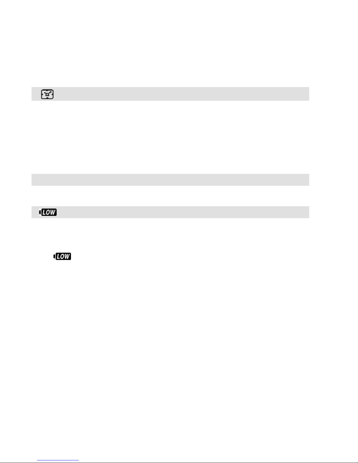
A/P
Clock Time: 12H/24H Alternative
1. When the user sets the clock time in Data Setting Mode, there
are two formats for option-- 12H and 24H.
2. 12H means 12 hours. In this format, A refers to AM; P refers to
PM. 24H means 24 hours.
3. When in the sleep mode, only the clock time will be displayed
on the screen.
0
C/ 0F Current Temperature
Press button B for 1 second to view the current temper ature
Low Battery Indicator
1. When the low-battery indicator appears on the display, it's time
to get a new battery.
2. Replace the battery with a new one A.S.A.P. when the symbol
blinks on the display. Otherwise, the new data of some
functions will not be stored into the computer.
3. If you do not change the battery in a few hours, the computer
may s till work for a few days. The data will be display ed as usual,
but the new data will not be stored before the battery is
changed.
4. To save battery power, there's no EL backlight when the
low-battery symbol is blinking.
Page 27
27
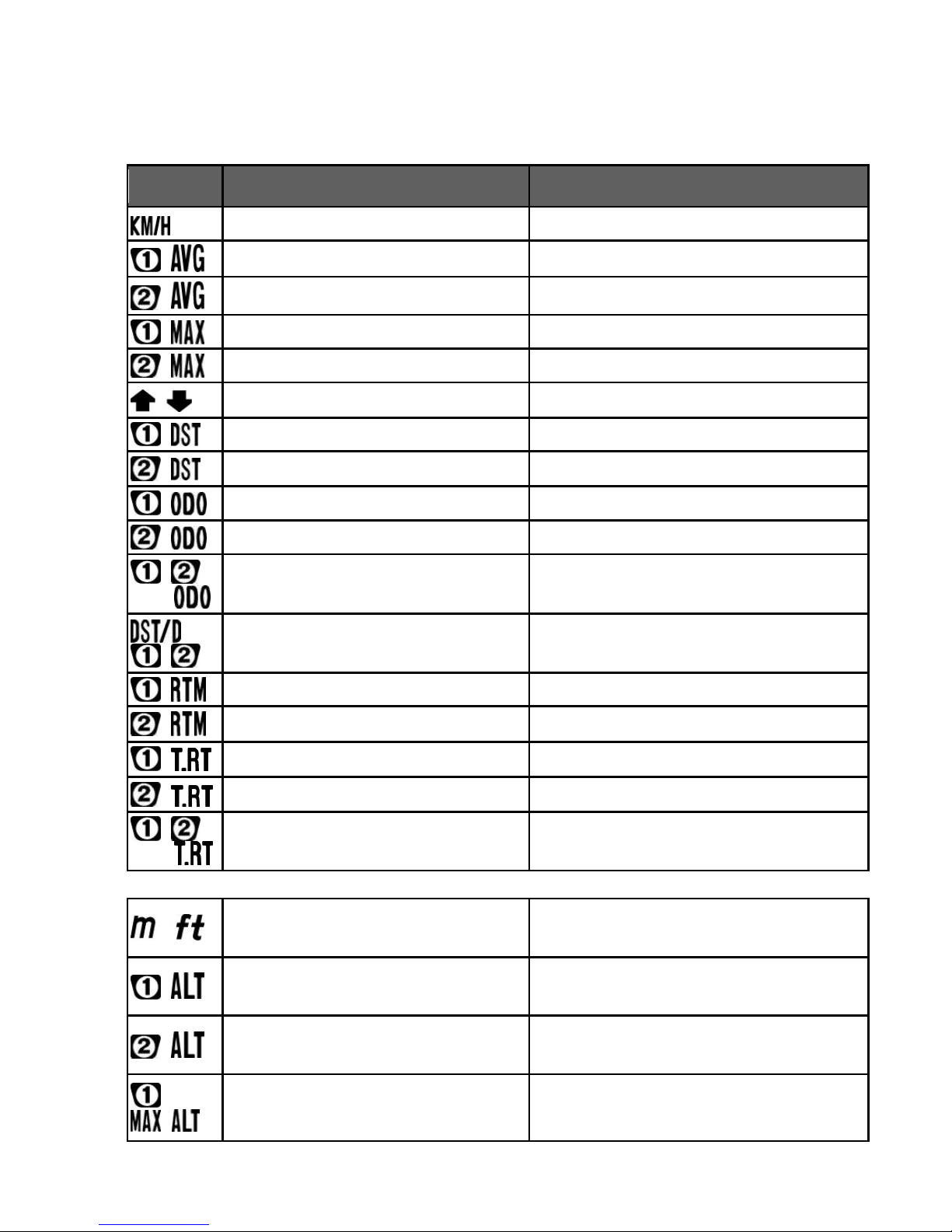
Technical Specifications
Symbol
Function
Range
Current Sp ee d
0-199.9 km/h (0-120.0m/h)
Avera ge Spee d f or Bike 1 0-199.9 km/h (0-120.0m/h)
Avera ge Spee d f or Bike 2 0-199.9 km/h (0-120.0m/h)
Maxi m um Speed f or B ik e 1 0-199.9 km/h (0-120.0m/h)
Maxi m um Speed f or B ik e 2
0-199.9 km/h (0-120.0m/h)
Pace Arrow
Compared with average speed
Trip Dis tance for Bike 1
0-999.99 km/mile
Trip Dis tance for Bike 2 0-999.99 km/mile
Odometer f or Bik e 1
0-999999km/mile
Odometer f or Bik e 2
0-999999km/mile
Total Odometer
(Bike 1 + Bik e 2)
0-1999999km/mile
Distance Per Day 0-999.99 km/mile
Riding Time for Bike 1
0H:00M:00S-99H:59M:59S
Riding Time for Bike 2
0H:00M:00S-99H:59M:59S
Total Riding Time for Bike 1
0H:00M:-9999H:59M
Total Riding Time for Bike 2
0H:00M:-9999H:59M
Total Riding Time (Bike 1 +
Bike 2)
0H:00M-19999H:59M
Current Al ti t ud e
-500m - 8000m
(-1640ft - 26240ft) UNIT:1m/3ft
Accumulated Alti t u de Gains
for Bike 1
0-99999m
(0-99999ft)
Accumulated Altitude Gains
for Bike 2
0-99999m
(0-99999ft)
Maxi m um Alti tud e f or
Bike 1
-500m - 8000m
(-1640ft - 26240ft)
Page 28
28
Maxi m um Alti tud e f or
Bike 2
-500m - 8000m
(-1640ft - 26240ft)
Total Accumula
ted Altitude
Gains for Bik e 1
0-999999m
(0-999999ft)
Total Accumulated Altitude
Gains for Bik e 2
0-999999m
(0-999999ft)
Total Accumulated Altitude
Gains (Bik e 1+ Bi k e 2)
0-1999999m
(0-999999ft)
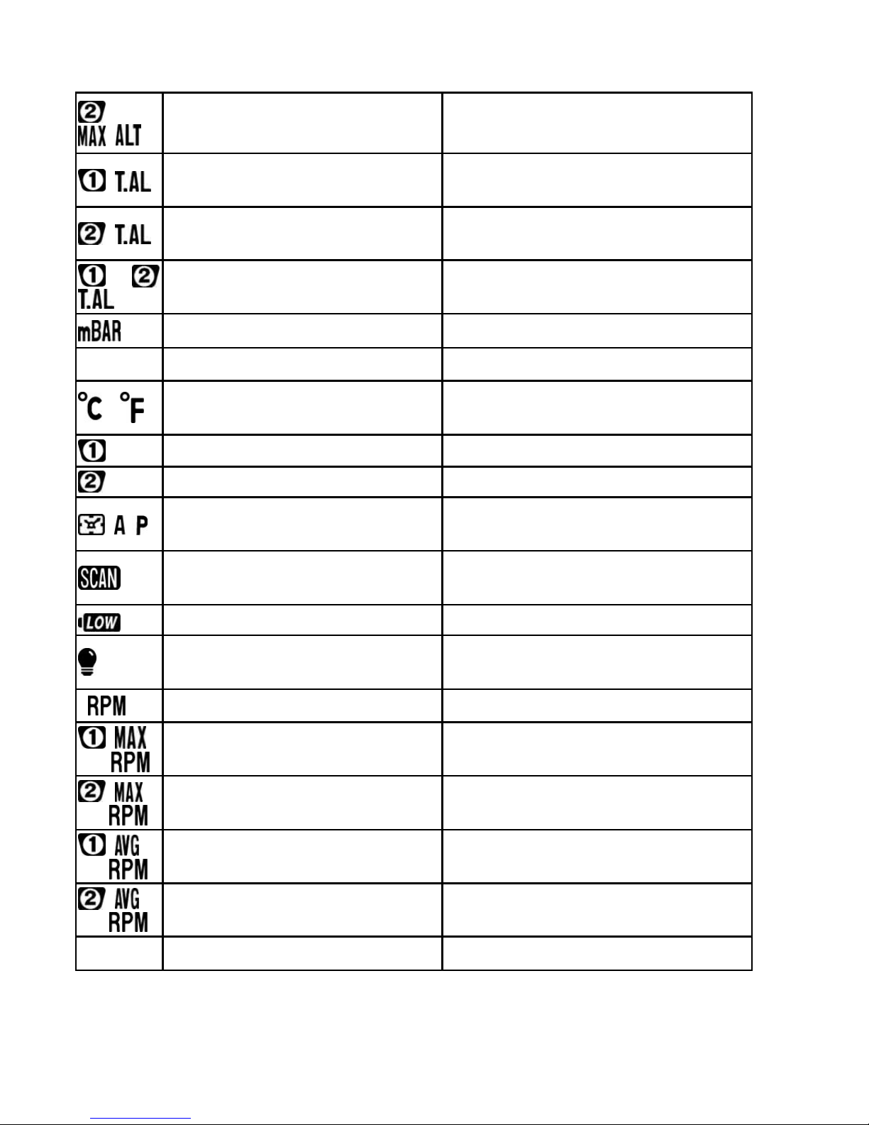
Barometer 300 - 1100 mbar
Unit Selection Meter/feet, °C/°F, kilometer/mile
Current Temperature
-10°C ~ 60°C
(14°F ~ 14 0° C )
Circ um fer ence for Bike 1 0-3999mm (default: 2155mm)
Circ um fer ence for Bike 2 0-3999mm (default: 2050mm)
12/24H Clock
1H:00M:00S-12H:59M:59S,
0H:00M:00S-23H:59M:59S
Auto-Scan
Automatically shifted to the next
per 5 secon ds
Low Batter y In di c at or
EL Back-light
Light for 2 seconds after each
press
Current RPM 0-199RPM
Maximum RPM for Bike 1 0-199RPM
Maximum RPM for Bike 2 0-199RPM
Average RPM for Bike 1 0-199RPM
Average RPM for Bike 2 0-199RPM
LCD Brightnes s
Levels 1 - 4
Page 29

29
General Specifications
Operating Temperatu re 0°C - 50°C (32°F - 122 °F)
Storage Temperatur e: -10°C - 60°C (14°F - 140°F)
Sensor & Transmitter: No-contact magnet sensor with
wireless transmitter
Suitable Fork Sizes: 12 mm - 50 mm (0.5" - 2.0")
Battery Operating Life:
CR2032 in Main Unit About one year (based on the
average riding time of 1.5 hours
per day)
CR2032 in Speed Transmitter Around 24000 km ( 15000 miles)
CR2032 in RPM Transmitter Around 600 hours
Dimensions & Weight (Main Unit): 46 x 57.3 x 19.7 mm, 37.15 g
The specifications and design are subject to change without prior
notice.
Page 30

30
Precautions
1. Watch the road. Don't pay much attention to your cycle computer
functions during riding to avoid accidents.
2. Don't expose the main unit to direct sunlight for a long time while
you're not riding with it.
3. Never disassemble the device or the accessories.
4. Don't poke a needle or any poin ted articl e into the hole o n th e
bottom of the main unit. To poke anything into the hole may
damage the pressure sensor inside the device.
5. Check the positions of the sensor and magnet, and check the gap
between both pa rts regularly. M ak e sure they are a lw ays in norm al
condition.
6. Use a dry or slightly damp cloth to clean the computer when
necessary. Do not use thinner, alcohol or benzine to clean the
product.
7. Be alert to the sudden weather change during long-distance riding
to avoid danger. And sudden change in temperature may cause a
temporary incorrect altitude display.
Page 31

31
Trouble S hoot ing
Problem
Check the following:
Solutions
No display
1.Does the battery
have power?
2.Is the battery
installation correct?
1.Replace the battery with a
new one.
2.Make sure the positive pole
of the battery faces the
battery cap.
Speed not
displayed
or wrong
displayed
1.
Is the computer in the
setting mode?
2.Are the magnet and
the sensor in the
correct position? Is
the gap between
both parts correct?
3. Is the wheel
circumference
setting correct?
4. Is the sensing
distance between
the main unit
and the
sensor too long?
5. Is the battery for the
sensor nearly
exhausted?
6. Is there any strong
interference source
nearby?
1. Refer to the setting
procedures to finish the
setting.
2.Refer to the installation
manual and correct the
positions and gap.
3. Refer to "Wheel
Circumference
Measurement and Setting"
and enter a correct value.
4. Refer to the installation
manual and adjust the
distance
between the main unit and
the sensor or adjust the
angle of the sensor.
5. Replace the battery with a
new one.
6. Stay away from the strong
interference source.
Irregular
Display
Refer to "Main Unit Setup"
and initiate the computer
again.
LCD is
black.
Did you expose the
main unit to the direct
sunlight for a long time
when it was not in use?
Put the main unit in the shade
to let it return to normal state.
Page 32

32
Display is
slow.
Is the temperature
below 00C (320F)?
The computer will return to
normal state when the
temperature rises.
Low-battery
symbol is
blinking.
Replace the battery in the
main unit with a new one.
Altitude not
displayed
or wrong
displayed
1. Did you calibrate the
altitude before riding?
2.Is the hole for
measuring the air
pressure on the
bottom of the main
unit clean?
1.Refer to "Overview of
Button Operation" and
calibrate the altitude before
each ride.
2.Always keep the hole for
measuring the air pressure
clean. Do not poke
anything into the hole to
avoid damage.
 Loading...