

Page 1
Compressed Air Foam System
Installation / Operation Manual
Class1 ◆ A Unit of IDEX Corporation
607 NW 27th Avenue
Telephone: 352-629-5020
Web..........www.class1.com
◆ Ocala, FL 34475 U.S.A.
◆ FAX: 352-629-3569
Manual p/n: 029-0020-85-0
Page 2
APPARATUS INFORMATION
ENGINE ______________________________________________
TRANSMISSION _______________________________________
MAXIMUM CAFS ENGINE RPM ___________________________
CAFS ENGINE SPEED RANGE ___________________________
NOTICE !
Class1 cannot assume responsibility for product failure resulting from improper
maintenance or operation. Class1 is responsible only to the limits stated in the
product warranty. Product specifications contained in this manual are subject to
change without notice.
All Class1 products are quality components -- ruggedly designed, accurately
machined, precision inspected, carefully assembled and thoroughly tested. In
order to maintain the high quality of your unit, and to keep it in a ready condition, it
is important to follow the instructions on care and operation. Proper use and good
preventive maintenance will lengthen the life of your unit.
ALWAYS INCLUDE THE UNIT SERIAL NUMBER
IN YOUR CORRESPONDENCE.
ECO NO REV CHANGE FROM BY DATE APVD
0000 A INITIAL RELEASE LwH 02/00/2006
Manual p/n: 029-0020-85-0, Rev. -A
Printed in U.S.A.
Class 1
A Unit of IDEX Corporation
Ocala, FL 34475 USA
DRAWN BY LwH ISSUE DATE COPYRIGHT ©
CHECKED BY 02/00/2006
NOT TO BE REPRODUCED OR USED TO
MAKE OTHER DRAWINGS OR MACHINERY.
© Class 1 2006
All Rights Reserved
Page 3

Table of Contents ❑
Contents Page
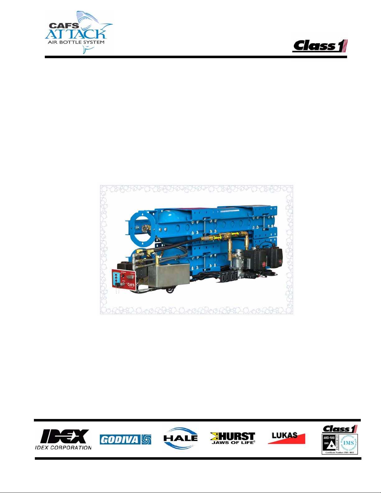
CAFSAttack Air Bottle System
1 Safety precautions ................................................................................................... 7
1.1 General Guidelines............................................................................................................. 7
1.2 Air Bottle Cylinders.......................................................................................................... 12
Brief Overview ..................................................................................................................................12
SCBA Fill Station ..............................................................................................................................14
1.3 Air Filter Element.............................................................................................................. 14
1.4 Emergency Shut-Down .................................................................................................... 14
2 Introduction........................................................................................................... 15
2.1 Overview ........................................................................................................................... 15
Figure 2-1: CAFSAttack System Overview.........................................................................16
2.2 Smart-Switch Controller (SPC) ....................................................................................... 18
OPEN Button, Discharge Valve........................................................................................................18
Figure 2-2: Smart-Switch Controller - SPC......................................................................... 19
CLOSE Button, Discharge Valve......................................................................................................19
LED Indicator Array (Bar Graph) ...................................................................................................... 19
WET (+) Button.................................................................................................................................19
Press and Release..................................................................................................................... 19
Press and Hold...........................................................................................................................20
LED Indicator .............................................................................................................................20
DRY ( - ) Button ................................................................................................................................ 20
Press and Release..................................................................................................................... 20
Press and Hold...........................................................................................................................20
LED Indicator .............................................................................................................................20
2.3 CAFSAttack Operator Control Panel.............................................................................. 21
Figure 2-3: CAFSAttack Operator Control Panel ................................................................21
CAFS Enable ON/OFF Switch..........................................................................................................21
HIGH Pressure Indicator...................................................................................................................22
Air Bottle OPEN/CLOSE Valve.........................................................................................................22
Intelli-Tank Air Level Indicator ..........................................................................................................22
Air Bottle FILL Coupling....................................................................................................................22
3 Receiving and inspection ...................................................................................... 23
3.1 Receiving .......................................................................................................................... 23
Items Furnished................................................................................................................................23
Items Required, by Builder/Installer..................................................................................................23
CAFSAttack Air Bottle System Installer / Operator’s Guide
p/n: 209-0020-85-0
3
Page 4

❑ Table of Contents
Contents - continued Page
3.1 Receiving - continued
Unpacking......................................................................................................................................... 24
Lifting The System............................................................................................................................ 24
4 Installation - Retrofit Full Size Pumper..............................................................25
4.1 General.............................................................................................................................. 25
Figure 4-1: CAFSAttack System Overview......................................................................... 25
4.2 DOT Air Bottle Cylinder Assembly................................................................................. 26
Figure 4-2: DOT Air Bottle Cylinder Assembly Layout Dimensions.................................... 26
4.3 Pressure Balancing Valve Assembly............................................................................. 27
Figure 4-3: Pressure Balancing (Regulator) Valve Assembly Layout.................................28
4.4 Foam Pump Installation .................................................................................................. 28
4.5 CAFSAttack Operator Panel Layout............................................................................... 29
Figure 4-4: Operator’s Panel Layout Dimensions............................................................... 29
4.6 SVS Discharge Manifold ................................................................................................ 30
Figure 4-5: Typical CAFSAttack SVS Discharge Manifold Assembly.................................30
4.7 Plumbing........................................................................................................................... 31
CAFSAttack Operator’s Control Panel .............................................................................................32
Figure 4-6: Typical HIGH Air Pressure Connections.......................................................... 32
Figure 4-7: 4,500 PSI HIGH Pressure Balancing Regulator and Dome Connections ........ 34
Figure 4-8: Pump-to-Balancer Valve Dome Connection .................................................... 34
Intake Air Pressure Gauge Layout Option ........................................................................................ 35
Figure 4-9: Typical Intake Air Pressure Gauge Layout....................................................... 35
Low Pressure CAFS Connect (2) ..................................................................................................... 35
Figure 4-10: Typical LOW Pressure CAFS Air Connections .............................................. 36
Air Discharge Moisture Drain............................................................................................................ 37
Figure 4-11: Typical Discharge Drain................................................................................. 37
Table 4-12: Tubing Size vs. Color ......................................................................................37
CAFS Air LOW Pressure Gauge Layout Option ...............................................................................38
Figure 4-13: CAFS Air LOW Pressure Layout Option ........................................................ 38
4.8 Electrical ........................................................................................................................... 38
Smart-Switch Controller - SPC (S1 and S2)..................................................................................... 40
Figure 4-14: Smart-Switch Controller Panel Cutout ........................................................... 40
Figure 4-15: SPC Connector, Back View ........................................................................... 40
CAFSAttack Main Wire Harness....................................................................................................... 41
Figure 4-16: Primary CAFS Wire Harness .........................................................................41
Primary Power and Ground ..............................................................................................................42
RFI / EMI .......................................................................................................................................... 43
Figure 4-17: Extra Cable Storage....................................................................................... 43
4
CAFSAttack Air Bottle S ystem Installer / Operator’s Guide
p/n: 209-0020-85-0
Page 5

Table of Contents ❑
Contents - continued Page
4.8 Electrical - continued
Flow Sensor Connections (FM1 and FM2) .......................................................................................43
Air Supply Valve, Electric Motor (MV2).............................................................................................43
Discharge Valve, Electric Motor (MV1).............................................................................................44
On/Off Switch (SA3), Operator Control Panel .................................................................................. 44
Figure 4-18: On/Off Switch Connection..............................................................................44
4.9 Installation and Delivery Check List...............................................................................45
4.10 Start Up Check List .......................................................................................................... 46
Electrical ........................................................................................................................................... 46
Air and Water.................................................................................................................................... 46
4.11 System Installer Start-Up................................................................................................. 48
Initial System Power Check..............................................................................................................48
System Operation Check..................................................................................................................48
For FoamLogix...........................................................................................................................48
For CAFSAttack ......................................................................................................................... 49
5 Preset calibration .................................................................................................. 51
5a.1 Smart-Switch calibration ................................................................................................. 51
Figure 5-1: Smart-Switch Calibration Overview..................................................................51
To calibrate a WET consistency... ....................................................................................................52
To calibrate a DRY consistency........................................................................................................53
5a Basic operation ...................................................................................................... 54
5a.1 Starting CAFSAttack ........................................................................................................ 54
5a.2 Shutting-down CAFSAttack ............................................................................................ 56
5a.3 Emergency Shut-Down .................................................................................................... 56
6 Routine maintenance ............................................................................................ 57
6.1 Maintenance Procedures.................................................................................................57
After each use...................................................................................................................................57
Monthly .............................................................................................................................................57
Every Two (2) Months.......................................................................................................................57
Annually ............................................................................................................................................58
6.2 Replace Filter Element..................................................................................................... 58
Figure 6-1: Filter Pressure Contamination Gauge ..............................................................58
6.3 Relieving HIGH PRessure................................................................................................ 59
Figure 6-2: Relieving HIGH Pressure .................................................................................59
CAFSAttack Air Bottle System Installer / Operator’s Guide
p/n: 209-0020-85-0
5
Page 6

❑ Table of Contents
Contents - continued Page
Appendix B: Foam Concentrate Compatibility..................................................61
Reference......................................................................................................................................... 63
Express Warranty .................................................................................65
Class 1..............................................................................................................................................66
7 Drawing / Manual Package ..................................................................................67
Drawings........................................................................................................................................... 68
Manuals............................................................................................................................................68
6
CAFSAttack Air Bottle S ystem Installer / Operator’s Guide
p/n: 209-0020-85-0
Page 7
1 Safety precautions
THE CLASS1 CAFSATTACK™ AIR BOTTLE COMPRESSED AIR FOAM
SYSTEM IS DESIGNED FOR OPTIMUM OPERATOR SAFETY. FOR ADDED
PROTECTION, PLEASE FOLLOW THE SAFETY GUIDELINES LISTED IN THIS
SECTION AND ADHERE TO ALL WARNING, DANGER, CAUTION AND
IMPORTANT NOTES FOUND WITHIN THIS MANUAL.
THIS SECTION ON SAFETY MUST BE CAREFULLY READ, UNDERSTOOD
AND ADHERED TO STRICTLY BY ALL INSTALLERS AND OPERATORS
BEFORE ATTEMPTING TO INSTALL OR OPERATE THE CAFSATTACK
AIR BOTTLE SYSTEM.
WHEN DEVELOPING DEPARTMENTAL APPARATUS OPERATING PROCEDURES, INCORPORATE THE WARNINGS AND CAUTIONS AS WRITTEN.
Safety Precautions ❑
IMPORTANT !
CAFSAttack is a trademark of Class1. All other brand and product names are the
trademarks of their respective holders.
1.1 GENERAL GUIDELINES
NOTICE !
THE PROCEDURES IN THIS MANUAL ARE GENERAL INSTALLATION AND
OPERATING PROCEDURES. THEY DO NOT REPLACE THE PROCEDURES,
POLICIES OR GUIDELINES ESTABLISHED BY THE AUTHORITY HAVING
JURISDICTION, NOR DO THEY REPLACE THE RECOMMENDATIONS AND
PROCEDURES PROVIDED IN THE APPARATUS MANUFACTURER'S
MANUAL.
REFER TO THE PROCEDURES PROVIDED BY THE AUTHORITY HAVING
JURISDICTION ON SETTING WHEEL CHOCKS (TO PREVENT ANY MOVEMENT OF THE APPARATUS), AS WELL AS LAYOUT AND CONNECTION OF
HOSES, VALVES AND DRAIN COCKS.
Read all instructions thoroughly before beginning
any installation and operation process.
CAFS Air Bottle Installer/Operation Guide
p/n: 029-0020-85-0
❑ Use care when removing the CAFSAttack system from its packaging
(skid) to prevent personal injury and/or damage to the system, especially
the external system connections.
7
Page 8

❑ Safety Precautions
THE CAFSATTACK AIR BOTTLE (H-CYLINDER) ASSEMBLY IS HEAVY AND
BULKY, WEIGHING OVER 500 LBS. (227 KGS.). ALWAYS REFER TO YOUR
BILL OF LADING FOR THE ACTUAL WEIGHT.
USE PROPER LIFTING SUPPORT DEVICES (OVERHEAD CRANE, STRAPS /
CHAINS, ETC.) CAPABLE OF HANDLING THE LOAD WHEN MOVING OR
INSTALLING THE ASSEMBLY. ATTACH LIFTING APPARATUS TO THE CYLINDER FRAME ONLY. DO NOT ATTACH STRAPS AROUND THE CYLINDERS.,
ESPECIALLY AT THE SHUT-OFF VALVE AREA. ALSO SEE FIGURE 4-2:
“DOT AIR BOTTLE CYLINDER ASSEMBLY LAYOUT DIMENSIONS” ON PAGE
26.
❑ Installation, maintenance and repairs should be performed by a trained
and qualified installer, or your authorized Class1 service representative.
Be sure the installer has sufficient knowledge, experience and the proper
tools before attempting any installation. DO NOT permit untrained personnel to install, use or maintain the CAFSAttack system.
WARNING !
Installation, use or repairs performed by persons not properly trained
may cause equipment failure that could result in serious bodily injury,
sickness or death.
❑ The installer is responsible for observing all instructions and safety
precautions in his or her daily routine as dictated by regional safety
ordinances or departmental procedures.
❑ Periodic inspection and scheduled maintenance of the equipment is
required for continued safe operation. A separate label is affixed to the
operator’s panel indicating the test date stamped on the cylinders and
the date the cylinders next require testing.
❑ Read and follow the precautions on all compressed gas cylinder labels.
❑ The frequency of servicing is the responsibility of the end-user based
upon the application.
❑ Never allow problems or lack of maintenance to go unreported.
❑ DO NOT permanently remove or alter any guarding or insulating devices,
labels, plates or instruction plates, or attempt to operate the system
when these items are removed. Various labels and/or instruction plates
are also located on the apparatus operator’s panel.
Make sure all access/service panels, covers, labels and plates are
installed, closed and latched tight, where applicable.
❑ DO NOT remove or alter any hydraulic or pneumatic connections, electri-
cal devices, etc. DO NOT tamper with or disconnect safety features. DO
NOT add or remove structural parts. Doing so voids the CAFSAttack
warranty.
8
CAFS Air Bottle Installer/Operation Guide
p/n: 029-0020-85-0
Page 9

Safety Precautions ❑
Any of the preceding could effect system capacity and/or safe operation
of the system and is a serious safety violation which could cause personal injury or death, could weaken the construction of the system or
could affect safe operation of the CAFSAttack Air Bottle System.
WARNING !
NO MODIFICATIONS OR ADDITIONS MAY BE MADE TO THE CAFSATTACK
AIR BOTTLE SYSTEM WITHOUT PRIOR WRITTEN PERMISSION FROM:
Class1
A Unit of IDEX Corporation
607 NW 27th Avenue
Ocala, FL 34475 U.S.A.
Telephone ......352-629-5020
Fax................. 352-629-3569
Web:...............www.class1.com
❑ Nozzle selection – Class1 does not recommend any specific type or
brand of nozzle for use with the CAFSAttack system.
Each fire department must conduct its own evaluation to ensure an
appropriate nozzle choice for the various types of hazards encounter.
Each fire department must develop associated operational procedures
and guidelines. Class1 does not recommend or claim suitability or fitness for any given nozzle brand or style.
WARNING !
ONCE A NOZZLE HAS BEEN SELECTED IT IS IMPERATIVE TO PROVIDE
AMPLE TRAINING IN THE USE OF THE NOZZLE.
OPEN CAFS NOZZLES “SLOWLY” AND MAKE SURE THE NOZZLE IS
SECURED AGAINST REACTION FORCES.
❑ Inspect the pressure balancing regulator valves and interconnecting
components (HIGH pressure side) for leaks before each use.
CAFS Air Bottle Installer/Operation Guide
p/n: 029-0020-85-0
WARNING !
BE SURE TO WEAR SAFETY GLASSES WHEN SERVICING THE HIGH
PRESSURE SYSTEM OR WHEN REMOVING AND/OR INSTALLING HIGH
PRESSURE PARTS.
9
Page 10
❑ Safety Precautions
Also see Tescom “Safety, Installation and Operation Precautions” guide
lines, located at the back of this manual.
If a balancing regulator valve or other component in the system shows
signs of a leak or malfunction, the CAFSAttack system must be removed
from service immediately and repaired and tested before retuning to
service.
ONCE THE AIR CYLINDERS ARE FULLY CHARGED AND THE SYSTEM IS
ENERGIZED, ALL HIGH PRESSURE LINES BETWEEN THE CYLINDER SHUTOFF VALVES AND THE PRESSURE BALANCING REGULATOR VALVES,
INCLUDING THE AIR FILTER, ARE EXPOSED TO HIGH PRESSURES (4,500
PSI / 310 BAR).
DO NOT PERFORM ANY SERVICE TO THE HIGH PRESSURE SIDE UNTIL THE
SYSTEM PRESSURE IS RELIEVED. SEE SECTION “6.3 RELIEVING HIGH
PRESSURE,” ON PAGE 59 FOR ADDITTIONAL INFORMATION.
DANGER !
❑ DO NOT operate the system with just air and water. Shut off the air sup-
ply whenever the foam tank is empty.
CAUTION !
COLD WEATHER ENVIRONMENTS CAN CAUSE SOME COMPONENTS TO
FREEZE AND RESTRICT AIR FLOW. COMPONENTS MUST BE THAWED
BEFORE CONTINUING CAFS OPERATION.
❑ NEVER fully empty the air-bottle cylinders. Always maintain a positive
pressure (approximately 50 to 100 PSI / 4 to 7 BAR) within the cylinders.
Positive pressure ensures against moisture and/or dirt contamination in
the tanks, which could also flow back and contaminate the SCBA
recharging cylinders.
Failure to comply could result in serious bodily injury, sickness or
death.
❑ To prevent electrical shock always disconnect the primary power source
before attempting to service any part of the CAFSAttack system.
❑ All electrical systems have the potential to cause sparks during service.
Take the necessary precautions to eliminate explosive or hazardous
environments during any installation and/or service.
10
❑ To prevent system damage or electrical shock, the main power supply
wire must be the last connection made to the CAFSAttack system.
❑ The CAFSAttack system is designed for use on negative (-) ground,
direct current, electrical systems only.
CAFS Air Bottle Installer/Operation Guide
p/n: 029-0020-85-0
Page 11

Safety Precautions ❑
❑ Always disconnect the power cable, ground straps, electrical wires and
control cables from the smart-switch control unit or other CAFSAttack
system equipment before electric arc welding at any point on the apparatus. Failure to do so could result in a power surge through the unit that
could cause irreparable damage.
❑ Before connecting the cord sets and wiring harnesses, inspect the seal
washer in the female connectors. If the seal washer is missing or damaged water can enter the connector causing pin and terminal corrosion.
This could cause possible system failure.
❑ DO NOT operate or fill (recharge) the air system at pressures higher than
the maximum rated system pressure of 4,500 PSI (310 BAR), as stated
on the WARNING placard located near the air cylinders.
If the “Rupture Disk” has ruptured due to over pressurization, the reason
for the rupture mst be determined and the cylinders must be visually
inspected and re-hydrostatic tested as stated in regulation 49 CFR
178.37. Failure to comply and re-certify the cylinders could lead to catastrophic failure resulting in serious bodily injury, sickness or death.
❑ DO NOT operate the CAFS system at pressures above 150 PSI (10
BAR), as stated on the WARNING placard on the operator’s panel.
❑ Use only piping or tubing, hose and fittings which are rated at or above
the maximum pressure rating at which the CAFSAttack system operates.
Also see heading “Air Bottle Cylinders” on page 12.
❑ Relieve all system pressure, then drain all foam concentrate and water
from the system before servicing any of its component parts.
❑ DO NOT mount a radio transmitter or transmitter cables in direct or close
contact with the CAFSAttack smart-switch controllers. Direct contact
could cause electrical interference and disrupt controller operations.
❑ DO NOT connect the CAFSAttack main power lead to small leads that
are supplying some other device, such as a light bar or siren. The
CAFSAttack requires ?? AMP minimum current.
❑ When operating the CAFSAttack and the Hale FoamLogix in Simulated
Flow Mode an outlet for the foam concentrate must be provided to prevent excessive pressure buildup in the discharge piping or hoses.
❑ Foam tank “low level” sensors must be utilized to protect the foam pro-
portioner from dry running. Failure to use “low level” sensors voids the
warranty.
❑ Make sure the foam tank and foam concentrate suction hoses are clean
before making the final connection to the foam pump. If necessary, flush
the tank and hoses prior to making any connections.
CAFS Air Bottle Installer/Operation Guide
p/n: 029-0020-85-0
❑ Also review your specific FoamLogix Installation and Operation Manual
(FoamLogix Model 2.1A, Hale p/n: 029-0020-74-0; FoamLogix Model 3.3
and 5.0, Hale p/n: 029-0020-68-0) for additional safety information.
11
Page 12

❑ Safety Precautions
1.2 AIR BOTTLE CYLINDERS
The CAFSAttack system uses HIGH pressure, compressed air storage cylinders (4,500 PSI / 310 BAR) which are in compliance with NFPA 1989
“Standard on Breathing Air Quality for Fire and Emergency Services Respiratory Protection.” For NFPA 1901 compliance, when a breathing air system
or a utility air system is mounted on fire apparatus the following requirements must apply:
CAUTION !
INSTALLATION OF THE CAFSATTACK SYSTEM MUST MEET NFPA #1901,
CHAPTER 25 “AIR SYSTEMS” REGULATIONS, INCLUDING ALL
SUBSEQUENT CHAPTERS OR REGULATIONS, I.E., “ASME” AND/OR “DOT”
AS STATED IN NFPA 1901 REGULATION. A SAMPLE LISTING FROM CHAPTER 25 “AIR SYSTEMS REGULATIONS” THAT APPLY AND MUST BE
ADHERED FOLLOWS:
CHAPTER # ........................... TITLE
25.2 ........................................ Provisions Applying to All Air Systems
25.2.5 ..................................... Assembly and Installation Practices
25.2.5.2 .................................. Hot Surface
25.2.5.4 .................................. Locking Devices
25.2.7 ..................................... General Piping Installation
25.2.8 ..................................... Flexible Hose
25.2.9 ..................................... Operator’s Panel and Controls
25.2.‘0 .................................... Maintainability
25.2.11 ................................... Labels and Plates
25.2.12 ................................... Documentation
25.2.13 ................................... Training and Instructions
25.5 ........................................ Air Storage Systems
25.5.1 ..................................... Transportable Air Tanks
25.5.7 ..................................... Air Tank Mounting
25.5.8 ..................................... Air Tank Valve Control and Monitoring
25.7 ........................................ Air Supply Regulation
25.11 ...................................... Air Hose
25.14 ...................................... Testing
12
Brief Overview
❑ Air tanks must comply with regulation 49 CFR 178.37, “Specification
3AAA and 3AAAX Seamless Steel Cylinders” or 29 CFR 1910.169, “Air
Receivers.”
CAFS Air Bottle Installer/Operation Guide
p/n: 029-0020-85-0
Page 13

Safety Precautions ❑
Also review and adhere to regulation NFPA 55: “Standard for the Storage, Use and Handling of Compressed Gases and Cryogenic Fluids in
Portable and Stationary Containers, Cylinders, and Tanks.”
CAUTION !
THE AIR CYLINDERS MUST BE FILLED WITH “BREATHING AIR” QUALITY
AIR. HOWEVER, THIS AIR IS “NOT SUITABLE” FOR BREATHING AIR APPLICATIONS (SCBA). OPEN AND CLOSE AIR CYLINDER VALVES “SLOWLY.”
ALWAYS “CLOSE” THE AIR VALVE WHEN THE CAFSATTACK SYSTEM IS
NOT IN USE.
❑ The air system must be designed and constructed to withstand the
stresses, vibrations and other conditions found when mounted on a fire
apparatus and being used in mobile service.
❑ Air tanks must be mounted in an arrangement that will hold the tanks in
all types of mobile use. Protective devices must be provided to protect
the air tanks, valves and associated piping and/or hoses from damage as
a result of accidental impact.
❑ Each DOT cylinder, valve, hose and/or tubing must successfully with-
stand a “Hydrostatic Test” as stated in regulation 49 CFR 178.37.
The Hydrostatic Test must be performed at least once every five (5)
years.
Failure to successfully meet the test criteria as stated in regulation 49
CFR 178.13 indicates a system failure. The CAFSAttack system must
be removed from operation immediately and repaired and re-tested
before retuning to service.
❑ Valving used on transportable air tanks must be of the ASME type on
ASME cylinders and of the DOT type on DOT cylinders, or equal, for the
rated system pressure.
❑ The air system must be designed so that it can be stored and operated in
environments with relative humidity up to and including 100% (percent).
❑ Surfaces over 142° F (61° C) must be covered with a thermal insulating
material or must be mechanically guarded to protect the operator. If covering or guarding the surface affects the operation of the component, a
label must be provided that states “CAUTION!: Hot Surfaces When
Operating.”
❑ The air tanks must be located away from any heat-producing devices,
such as the generator engine or exhaust.
CAFS Air Bottle Installer/Operation Guide
p/n: 029-0020-85-0
❑ Locking devices - All screws, pins, bolts or other fasteners whose failure
could create a hazardous condition for personnel or equipment must be
equipped with locking devices. Safety wire, self-locking nuts, cotter pins,
lock washers and liquid-locking compounds are acceptable.
13
Page 14

❑ Safety Precautions
❑ All materials used in the air system must be corrosion resistant or treated
to resist corrosion unless the finished product is in continual contact with
a noncorrosive lubricant.
All pneumatic fittings, tubing and hoses must also be rated for the maximum allowable working system pressure.
❑ Flexible hose must be installed to prevent cuts, abrasions, exposure to
damage, excessive temperatures, damage from loose equipment and
excessive bending.
SCBA Fill Station
THE CAFSATTACK SYSTEM IS NOT DESIGNED OR INTENDED TO BE USED
AS A “SCBA FILL STATION.” THE CAFSATTACK SYSTEM MUST NOT BE
USED FOR OTHER THAN ITS INTENDED USE. DO NOT FILL SCBA BOTTLES
USING THE CAFSATTACK AIR CYLINDERS AS YOUR AIR SOURCE.
DANGER !
1.3 AIR FILTER ELEMENT
A visual differential pressure indicator enables the operator to read contaminated build up before the element is plugged, and includes an automatic
reset.
DANGER !
THE FILTER IS LOCATED IN THE SYSTEM HIGH PRESSURE LINE. YOU
MUST FIRST BLEED-OFF THE HIGH PRESSURE BEFORE ATTEMPTING TO
CHANGE AND/OR CLEAN THE FILTER ELEMENT. TO RELIEVE (BLEED-OFF)
THE SYSTEM HIGH PRESSURE, SEE SECTION 6.3 “RELIEVING HIGH PRESSURE” ON PAGE 59.
1.4 EMERGENCY SHUT-DOWN
1. Manually shut-off the air supply to the system - turn the CAFSAttack air
bottle valve, on the operator’s control panel, to the CLOSE position (O).
2. Set the CAFS ENABLE switch, on the operator’s control panel, to OFF (O).
3. Close the air bottle shut-off valves for each cylinder.
4. Also see heading “Emergency Shut-Down” on page 56.
14
CAFS Air Bottle Installer/Operation Guide
p/n: 029-0020-85-0
Page 15

2Introduction
2.1 OVERVIEW
The CAFSAttack Air Bottle Compressed Air Foam Pumping System is
designed for installation on new or for retrofit onto existing fire apparatus.
The CAFSAttack system must be considered an additional option on a fire
fighting apparatus and must not impair the operation of the basic system.
The performance of the original fire fighting system, as well as personal
safety, must not be compromised.
CAFSAttack offers accurate push-button, compressed air foam from a
stored air supply using Class1 “Smart-Switch” electronic technology. The
Class1 Smart-Switch provides enhanced fire fighter safety, performance
and ease of use. Two 200 cfm capacity pressure “balancing regulator”
valves “balance” water and air pressures.
Description ❑
Dual compressed air foam discharges provide variable foam consistancies. For example, one line can generate a “WET” quick draining foam blanket; while the second line could discharge “DRY,” shaving cream-like foam
for exposure protection.
The CAFSAttack DOT high pressure compressed air bottle cylinders are in
compliance with NFPA 1989 “Standard on Breathing Air Quality for Fire and
Emergency Services Respiratory Protection” regulations.
The CAFSAttack system is shipped in modular assembly form, completely
tested and ready for installation on full size municipal, forestry and skid
units. (See Figure 2-1: “CAFSAttack System Overview,” on page 16.)
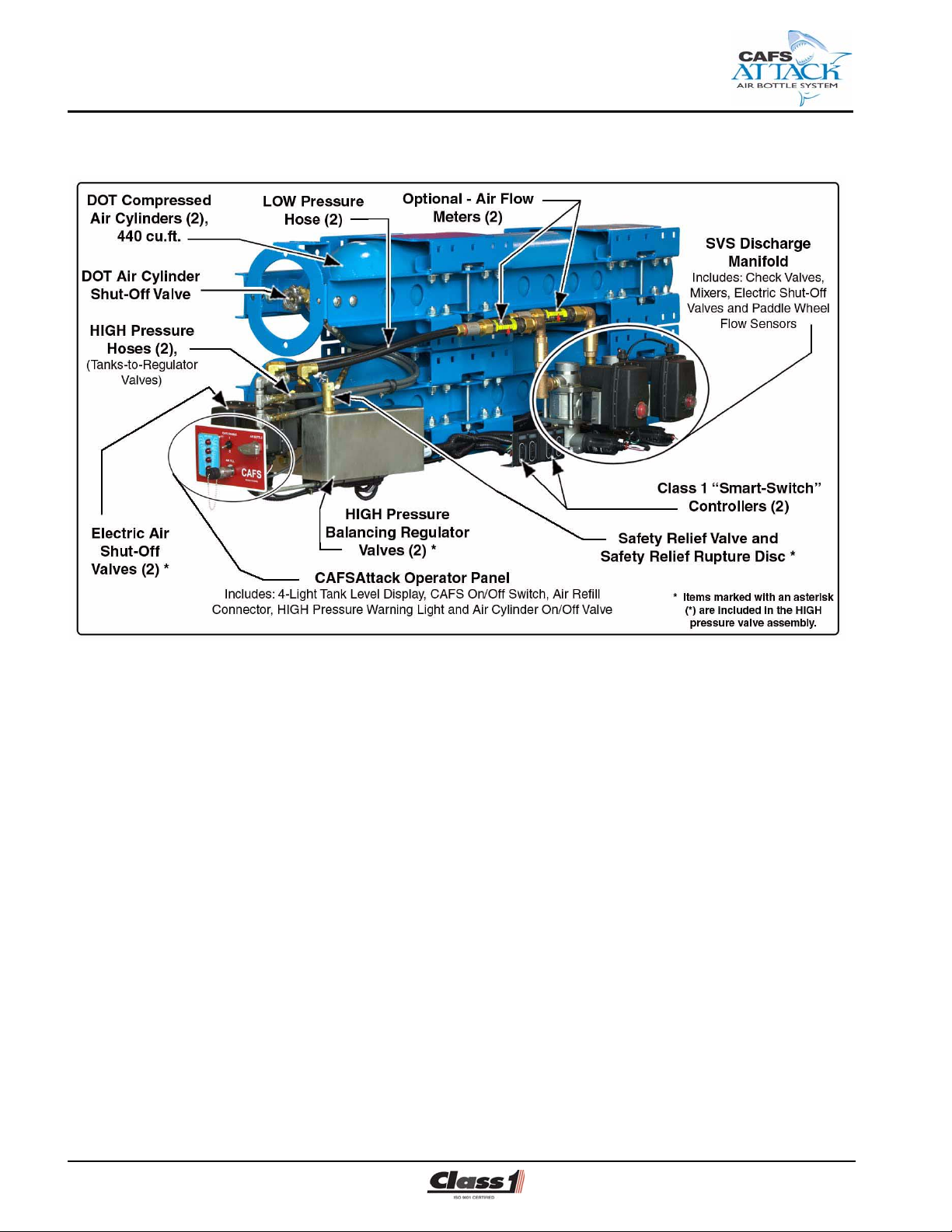
The CAFSAttack System includes the following modular assemblies:
❑ Dual DOT high pressure (4,500 PSI / 310 BAR) compressed air bottle
cylinders (H-cylinder type) having a capacity of over 440 cubic feet
of storage, fully assembled as a complete unit.
❑ Dual HIGH pressure (4,500 PSI / 310 BAR and 1,000 PSI / 69 BAR)
valve assembly
● The first high-to-low air pressure “balancing” regulator valve (4,500
PSI) is direct acting and dome loaded to provide constant discharge
pressure - 200 cfm capacity. The second valve (1,000 PSI) is also
direct acting and reduces pressure to 1,000 PSI for best overall
performance.
CAFS Air Bottle Installer/Operation Guide
p/n: 029-0020-85-0
15
Page 16
❑ Description
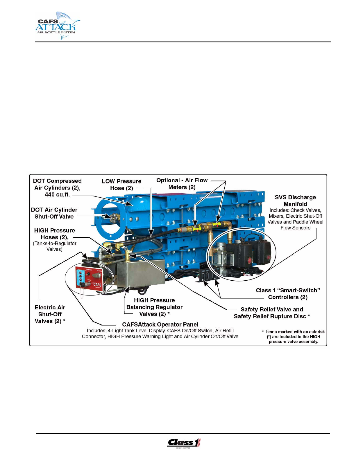
Figure 2-1: CAFSAttack System Overview
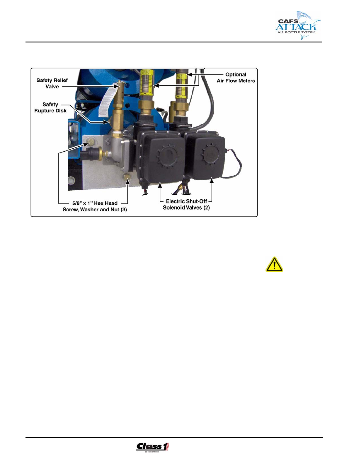
❑ HIGH pressure valve assembly - continued
● Tee-type air filter - used to remove any particulate contaminates from
the system. A multi-layered glass fiber element produces high efficiency silt-control filtration and provides for extended service intervals
and reduced maintenance cost.
A visual pressure indicator enables the operator to read contaminated
build up before the element is plugged, with an automatic reset.
● Two electrically-controlled open/close air shut-off valves.
● Pressure safety relief valve, set at 165 PSI (11.4 BAR).
● Pressure safety relief Rupture Disc, set at 350 PSI (24 BAR).
● Check valves to ensure separation of water, foam solution, foam con-
centrate and air.
❑ Discharge Manifold
● Two electrically-controlled shut-off valves, with valve position
indicator.
See separate SVS manual provided (Hale p/n: 209-0020-90-0) for
additional valve information.
16
● Mixing chambers.
CAFS Air Bottle Installer/Operation Guide
p/n: 029-0020-85-0
Page 17

Description ❑
● Paddle wheel flow sensors.
❑ CAFSAttack operator control panel
● Two Class1 “Smart-Switch” Controllers with LED bar graph array.
● Inteli-Tank high pressure air tank level indicator - four (4) RED indica-
tors lights, indicates cylinder tank charge remaining.
● On/Off CAFSAttack air enable switch, to activate the CAFSAttack
system.
● Amber HIGH pressure warning light, illuminates at pressures above
150 PSI (10 BAR).
● Quick connect high pressure air cylinder refill connection for an SCBA
Breathing Air High Pressure 4,500 PSI (310 BAR) Compressor System. SCBA station not included.
● Main air bottle open/close valve - introduces HIGH pressure air into
the system.
❑ HIGH pressure hose (2) - air bottle cylinders-to-pressure valves.
❑ LOW pressure hose (2) - high pressure air shut-off valves-to-SVS dis-
charge valves.
❑ FoamLogix foam pump, Model 2.1A - standard (not shown)
See separate manual for description, installation and operation of FoamLogix Electronic Foam Proportioning System (Hale p/n: 029-0020-74-0).
❑ CAFSAttack Installer / Operation Manual, Hale p/n:209-0020-85-0
Additional options, such as; FoamLogix Models 3.3 or 5.0, for higher foam
solution applications or the use of Class “B” type foams are available to further meet customer requirements.
IMPORTANT!
COMPONENTS ARE INSTALLED WHERE REQUIRED, PER CUSTOMER
ORDER AND/OR OPERATIONAL REQUIREMENTS. NOT ALL INSTRUCTIONS
HEREIN ARE INCLUSIVE. THEY ARE GENERAL GUIDELINES ONLY. INDIVIDUAL CHASSIS CONFIGURATION, BUILDER PRACTICES, ETC. DICTATE
WHEN AND WHERE COMPONENTS ARE INSTALLED.
CAFS Air Bottle Installer/Operation Guide
p/n: 029-0020-85-0
Using accepted assembly procedures, the CAFSAttack air cylinders may be
mounted on the apparatus in an arrangement that secures the cylinders in
all types of mobile use and where they are least susceptible to accidental
impact.
Once the cylinders are in place, the interconnecting valving, pressure
gauges, pneumatic lines and related components must be installed.
17
Page 18

❑ Description
Since the system is of the modular design, a minimum number of pneumatic
and electrical connections are required.
Mounting the FoamLogix 2.1A, 3.3 or 5.0 System includes installation of
the foam pump and motor assembly, in-line strainer and valve assembly and
low tank sensor. Refer to the following manual, based on the specific model
FoamLogix included with your system:
❑ FoamLogix Model 2.1A Installation and Operation Manual,
Hale p/n: 029-0020-74-0
❑ FoamLogix Model 3.3 and 5.0 Installation and Operation Manual,
Hale p/n: 029-0020-68-0
The CAFSAttack smar t-switches and air pressure level indicator are to be
mounted on the apparatus pump operator’s panel.
Once the major components are installed, see separate headings for pneumatic plumbing and electrical hookup instructions.
❑ Plumbing - see 4.7 “Plumbing” on page 31.
❑ Electrical - see 4.8 “Electrical” on page 38.
WARNING !
WHILE INSTALLING A CAFSATTACK SYSTEM MAKE SURE ALL SAFETY
REGULATIONS AND INSTRUCTIONS ARE FOLLOWED TO PROVIDE A SAFE
INSTALLATION. THOROUGHLY REVIEW SECTION 1 “SAFETY PRECAUTIONS” BEGINNING ON PAGE 7.
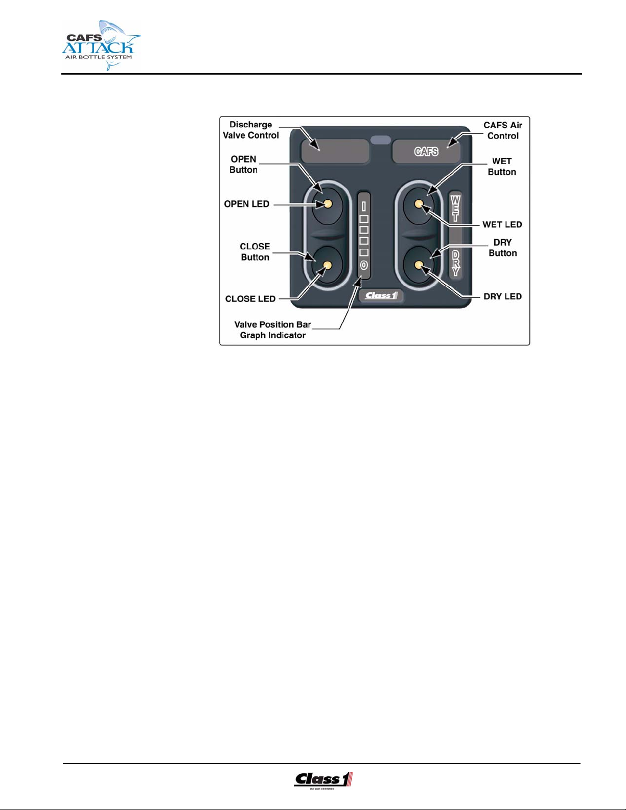
2.2 SMART-SWITCH CONTROLLER (SPC)
The “Smart-Switch” Panel Controller (SPC) is the primary controller for both
compressed air injection and discharge valve control. The SPC allows the
operator to inject air and control the consistency of the discharged finished
foam. (See Figure 2-2: “Smart-Switch Controller - SPC,” on page 19.)
OPEN Button, Discharge Valve
18
(See Figure 2-2: “Smart-Switch Controller - SPC,” on page 19.)
The OPEN button opens the water discharge valve to increase water or
foam solution (making a wetter solution). Holding the button pressed opens
the valve until the internal limit switch activates, indicating the fully OPENED
position.
CAFS Air Bottle Installer/Operation Guide
p/n: 029-0020-85-0
Page 19
Description ❑
Figure 2-2: Smart-Switch Controller - SPC
The OPEN button LED is ON steady during operation and flashes during
setup.
CLOSE Button, Discharge Valve
The CLOSE button closes the water discharge valve to decrease the water
or foam solution (making a dryer solution). Holding the button pressed
closes the valve until the internal limit switch activates, indicating the fully
CLOSED position. The CLOSE button LED is ON steady during operation
and flashes during setup.
LED Indicator Array (Bar Graph)
The OPEN / CLOSE bar graph LED indicator array illuminates from the bottom (O - fully closed) to the top (I - fully opened). It sequentially indicates
the approximate open / close position of the valve.
CAFS Air Bottle Installer/Operation Guide
p/n: 029-0020-85-0
WET (+) Button
Press and Release
Pressing and RELEASING the WET button sets and maintains the air injection rate at the Preset 2 * value, producing a WET foam concentrate.
19
Page 20

❑ Description
Pressing the WET button also immediately activates the FoamLogix controller in preparation for foam injection. When the system detects water is flowing, the appropriate air valve is opened.
Press and Hold
Press and HOLD the WET button for about ten (10) seconds to store a new
WET CAFS consistency at Preset 2. The entire display blinks once when
the setting is stored. Use the OPEN and CLOSE buttons to adjust the airto-foam solution ratio, thus the foam consistency.
LED Indicator
The WET button LED FLASHES when in the WET position and is ON
steady if the CAFS system is active and air is flowing into the corresponding
discharge.
DRY ( - ) Button
(See Figure 2-2: “Smart-Switch Controller - SPC,” on page 19.)
Press and Release
Pressing and RELEASING the DRY button sets and maintains the air injection rate at the Preset 1 * value, producing a DRY foam concentrate. Press-
ing the DRY button also immediately activates the FoamLogix controller in
preparation for foam injection.
When the system detects water is flowing, the appropriate air valve is
opened.
Press and Hold
Press and HOLD the DRY button for ten (10) seconds to store a new DRY
CAFS consistency at Preset 1. The entire display blinks once when the setting is stored. Use the OPEN and CLOSE buttons to adjust the air-to-foam
solution ratio, thus the foam consistency.
LED Indicator
The DRY button LED FLASHES when in the DRY position and is ON
steady if the CAFS system is active and air is flowing into the corresponding
discharge.
* Presets 1 and 2 are an established value by the end user and the installer/builder at
the time of installation to produce the required CAFS discharge. This assures the
correct DRY and WET consistency ever time the appropriate CAFS button is pressed.
20
CAFS Air Bottle Installer/Operation Guide
p/n: 029-0020-85-0
Page 21
Description ❑
IMPORTANT !
THE DUAL DISCHARGES AND SMART-SWITCH CONTROLLERS OFFER SEPARATE CONTROL FOR EACH DISCHARGE, I.E., ONE DISCHARGE CAN BE
SET FOR WET CAFS WHILE THE OTHER IS SET FOR DRY CAFS.
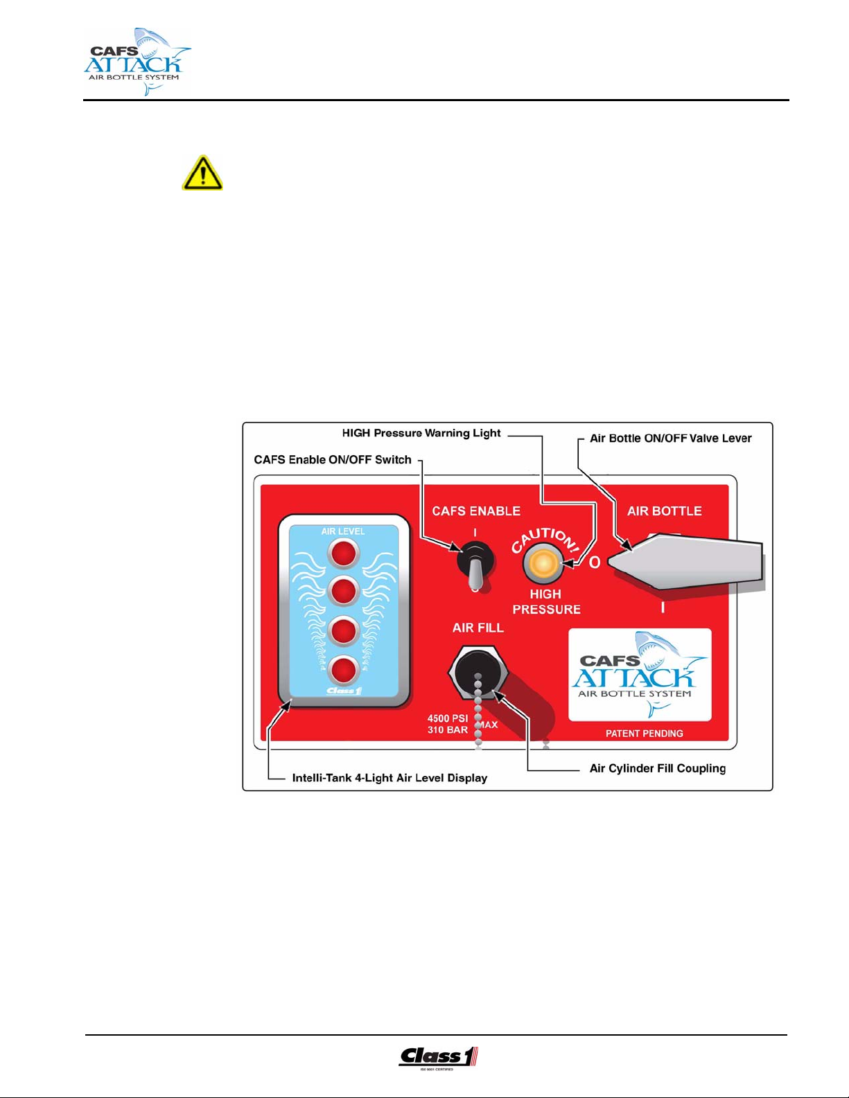
2.3 CAFSATTACK OPERATOR CONTROL PANEL
The CAFSAttack Operator Control Panel provides the means to enable
(turn ON) the CAFSAttack system and to supply, monitor and charge the air
pressure in the two DOT air cylinders. (See Figure 2-3: CAFSAttack Operator Control Panel.)
CAFS Air Bottle Installer/Operation Guide
p/n: 029-0020-85-0
Figure 2-3: CAFSAttack Operator Control Panel
The CAFSAttack operator control panel is a complete assembly. It must be
installed in a convenient location on the apparatus operator’s control panel.
CAFS Enable ON/OFF Switch
The CAFS Enable On/Off Switch allows the electrical power to the
CAFSAttack system components (0 = OFF; I = ON).
21
Page 22
❑ Description
HIGH Pressure Indicator
Also see Figure 2-3: “CAFSAttack Operator Control Panel” on page 21.
The HIGH pressure indicator (YELLOW) illuminates when the water/air
pressure is greater than 150 PSI (10 BAR). Pressure in excess of 160 PSI
(11 BAR) is discharged through the safety relief valve.
Air Bottle OPEN/CLOSE Valve
This open/close shut-off valve introduces HIGH air pressure to the system
(0 = CLOSED; I = OPEN).
Intelli-Tank Air Level Indicator
The 4-light air level indicator visually shows the air remaining in the HIGH
pressure air cylinders (bottles). See separate manual, located at the back
of this manual, for additional information.
CAUTION !
SYSTEM MAXIMUM PRESSURE MUST NOT EXCEED 4,500 PSI (311 BAR).
ALSO SEE HEADING “AIR BOTTLE CYLINDERS” ON PAGE 12.
Air Bottle FILL Coupling
The air FILL coupling allows charging of the 4,500 PSI (310 BAR) HIGH
pressure cylinders with a SCBA compressor system.
DANGER !
THE CAFSATTACK AIR BOTTLE FOAM PUMP SYSTEM IS NOT DESIGNED
OR INTENDED TO BE USED AS A “SCBA FILL STATION.” THE CAFSATTACK SYSTEM MUST NOT BE USED FOR OTHER THAN ITS INTENDED
USE.
22
DO NOT FILL SCBA BOTTLES USING THE CAFSATTACK AIR CYLINDERS AS
YOUR AIR SOURCE.
CAFS Air Bottle Installer/Operation Guide
p/n: 029-0020-85-0
Page 23

3 Receiving and inspection
3.1 RECEIVING
Before shipping from Class1 the CAFSAttack Compressed Air Foam Pumping System is factory inspected and tested. However, we recommend that
you:
1. Inspect the packaging for any signs of physical damage during shipment. Note
any apparent damage on the bill of lading and request the delivery agent to
sign it. Report the damage to Class1, Ocala, FL. and the shipping company.
2. Verify that the system configuration and options match your purchase order.
Report any discrepancies to Class1.
Receiving and Inspection ❑
Class1
A Unit of IDEX Corporation
607 NW 27th Avenue
Ocala, FL 34475 U.S.A.
Telephone . 352-629-5020
Fax ............ 352-629-3569
Web:.......... www.class1.com
Items Furnished
The CAFSAttack system is shipped with all OEM required connections
tagged for easy identification. For a listing of items furnished, see Section
2.1 “Overview,” beginning on page 15.
Also included are the necessary labeling, plates and instruction plates
which must be installed in their appropriate locations to ensure proper personal and system operating safety.
CAFS Air Bottle Installer/Operation Guide
p/n: 029-0020-85-0
Items Required, by Builder/Installer
The following items are a sampling of what might be required to complete
the installation, connecting the system to your apparatus. The items
required vary depending on your system configuration. Also see the FoamLogix Model 2.1A, 3.3 or 5.0 Manual for additional information.
23
Page 24
❑ Receiving and Inspection
❑ Appropriate air injection hose, 1/4” (6 mm), up 6,000 PSI (414 BAR)
❑ Appropriate discharge hose or piping, 1/4” (6 mm), up ??? PSI (???
BAR)
❑ Appropriate electrical wire, Type SXL, GXL or TXL
❑ Appropriate DOT air injection tube, 3/8” (9.5 mm)
❑ Appropriate LOW pressure drain and HIGH pressure tubing / hose, rec-
ommended - 3/8” (10 mm), up 6,000 PSI (414 BAR)
Unpacking
The CAFSAttack system is shipped partially assembled on two skids. One
skid contains the CAFSAttack air bottle cylinder module assembly. The
second skid contains the FoamLogix Pump Unit along with all supplied
loose items.
Use care when removing the CAFSAttack from its packaging (skid) to prevent injury and/or damage to the system, especially the external system
connections.
IMPORTANT!
EXERCISE CARE DURING UNPACKING AND INSTALLATION TO ENSURE
THAT THE IDENTIFICATION TAGS ARE NOT REMOVED BEFORE THE CONNECTIONS ARE MADE.
DO NOT REMOVE OR ALTER ANY HYDRAULIC OR PNEUMATIC CONNECTIONS WITHOUT WRITTEN APPROVAL FROM CLASS1. ALSO REVIEW SECTION 1 “SAFETY PRECAUTIONS” BEGINNING ON PAGE 7.
Lifting The System
WARNING!
THE CAFSATTACK AIR BOTTLE (H-CYLINDER TYPE) ASSEMBLY IS HEAVY
AND BULKY, WEIGHING OVER 500 LBS. (227 KGS.). SEE BILL OF LADING
FOR ACTUAL WEIGHT. USE PROPER LIFTING SUPPORT DEVICES (OVERHEAD CRANE, STRAPS/CHAINS, ETC.) CAPABLE OF HANDLING THE LOAD
WHEN MOVING OR INSTALLING THE SYSTEM. ATTACH LIFTING APPARATUS TO THE CYLINDER FRAME ONLY. DO NOT ATTACH STRAPS AROUND
THE CYLINDERS, ESPECIALLY THE SHUT-OFF VALVE AREA. ALSO SEE
FIGURE 4-2: “DOT AIR BOTTLE CYLINDER ASSEMBLY LAYOUT DIMENSIONS” ON PAGE 26.
24
CAFS Air Bottle Installer/Operation Guide
p/n: 029-0020-85-0
Page 25
Installer Installation ❑
4 Installation - Retrofit Full Size Pumper
4.1 GENERAL
Since most truck configurations are not the same, this section serves only
as a general guide for installation.
When installing the CAFSAttack system use the best accepted practices for
mounting. Review previous Section 3 “Receiving and inspection,” beginning
on page 23. Also see Figure 4-1: “CAFSAttack System Overview.”
CAFS Air Bottle Installer/Operation Guide
p/n: 029-0020-85-0
Figure 4-1: CAFSAttack System Overview
25
Page 26
❑ Installer Installation
4.2 DOT AIR BOTTLE CYLINDER ASSEMBLY
DANGER !
ALWAYS TREAT COMPRESSED AIR CYLINDERS WITH RESPECT. THEY
CONTAIN VERY HIGH PRESSURES (UP TO 4,500 PSI / 310 BAR). READ THE
MSDS AND FOLLOW PROPER PROCEDURES WHEN HANDLING AND USING
THESE CYLINDERS. ALWAYS FOLLOW THE RECOMMENDED SAFETY
PROCEDURES.
26
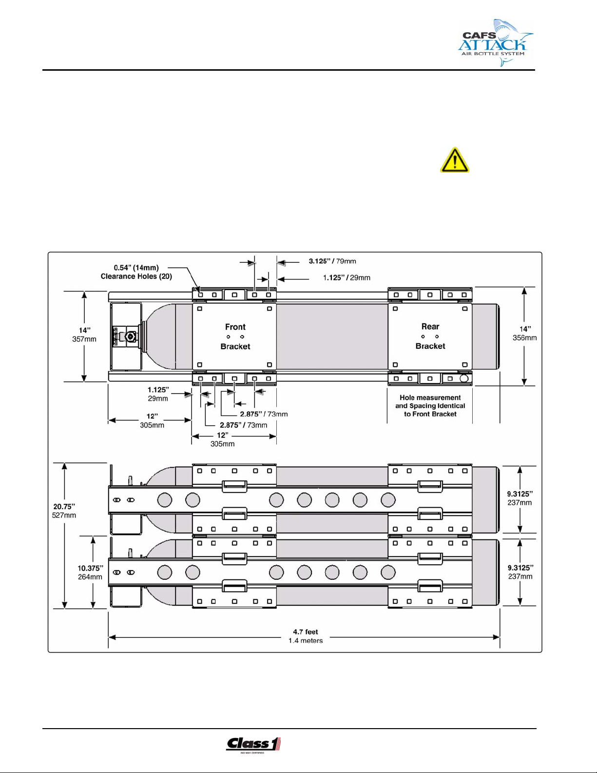
Figure 4-2: DOT Air Bottle Cylinder Assembly Layout Dimensions
CAFS Air Bottle Installer/Operation Guide
p/n: 029-0020-85-0
Page 27

Installer Installation ❑
IMPORTANT!
(SEE FIGURE 4-2: “DOT AIR BOTTLE CYLINDER ASSEMBLY LAYOUT DIMENSIONS,” ON PAGE 26.)
WHEN DETERMINING THE LOCATION FOR THE AIR BOTTLE CYLINDER
ASSEMBLY (WITH THE HIGH PRESSURE VALVE ASSEMBLY), IT IS RECOMMENDED TO INSTALL THE SYSTEM “ABOVE” THE PUMP WITH DOWNWARD
SLOPPING LINES TO PROMOTE POSITIVE DRAINAGE.
KEEP IN MIND PIPING RUNS, CABLE ROUTING, VISIBILITY, REQUIRED
OPERATOR ACCESS TO VALVE SHUT-OFFS AND OTHER INTERFERENCES
THAT COULD HINDER OR INTERFERE WITH PROPER SYSTEM
PERFORMANCE.
ALSO ENSURE THE ASSEMBLY IS INSTALLED IN AN AREA AFFORDING PROTECTION FROM ROAD DEBRIS AND EXCESSIVE HEAT BUILDUP AND WITH
THE LEAST EXPOSURE TO ACCIDENTAL IMPACT.
Drill the corresponding mounting holes and use minimum 5/8”, Grade 8
bolts with flat washers and lock nuts to bolt-down the air cylinder bracketry.
(See Figure 4-2: “DOT Air Bottle Cylinder Assembly Layout Dimensions,” on
page 26.)
An installation diagram is also located at the back of this manual to assist
with overall dimensions and clearances required for the various mounting
configurations. See Contents for a listing of the drawings.
For plumbing requirements, proceed to heading 4.7 “Plumbing” on page 31.
For electrical requirements, proceed to heading 4.8 “Electrical” on page 38.
4.3 PRESSURE BALANCING VALVE ASSEMBLY
The high pressure balancing regulator valve assembly is pre-mounted to
the front of the air cylinder tank assembly. The module is mounted using
three 5/8”, Grade 8 bolts with flat washers and lock nuts. (See Figure 4-3:
“Pressure Balancing (Regulator) Valve Assembly Layout,” on page 28.)
Additionally, there must be room for the WARNING ! placards as provided.
CAFS Air Bottle Installer/Operation Guide
p/n: 029-0020-85-0
IMPORTANT !
SHOULD IT BE REQUIRED TO RELOCATE THIS ASSEMBLY, IT IS RECOMMENDED TO INSTALL THE PRESSURE BALANCING VALVE ASSEMBLY
“ABOVE” THE PUMP WITH DOWNWARD SLOPING LINES TO INSURE POSITIVE DRAINAGE.
27
Page 28
❑ Installer Installation
Figure 4-3: Pressure Balancing (Regulator) Valve Assembly Layout
WARNING !
EXERCISE CARE NOT TO DAMAGE OR TWIST INTERCONNECTING HIGH
PRESSURE PNEUMATIC PIPING OR ACCIDENTALLY LOOSEN FITTING CONNECTIONS DURING ASSEMBLY. REMEMBER, THE SYSTEM MUST BE
HYDROSTATIC TESTED BEFORE USE AND SHIPPING TO THE CUSTOMER.
4.4 FOAM PUMP INSTALLATION
Detailed foam pump installation instructions are found in the FoamLogix
Electronic Foam Proportioner Installation and Operation Manual, packaged
with the FoamLogix assembly. Refer to the specific model FoamLogix system included with your CAFSAttack system.
❑ FoamLogix Model 2.1A Installation and Operation Manual,
Hale p/n: 029-0020-74-0
❑ FoamLogix Model 3.3 and 5.0 Installation and Operation Manual,
Hale p/n: 029-0020-68-0
28
CAFS Air Bottle Installer/Operation Guide
p/n: 029-0020-85-0
Page 29
Installer Installation ❑
Note: For CAFSAttack systems, the main cable harness included with the Foam-
Logix system differs from what is shown in the FoamLogix manual. For an overview of the replacement cable used with CAFSAttack, see Section 7, “Drawing /
Manual Package” on page 67.
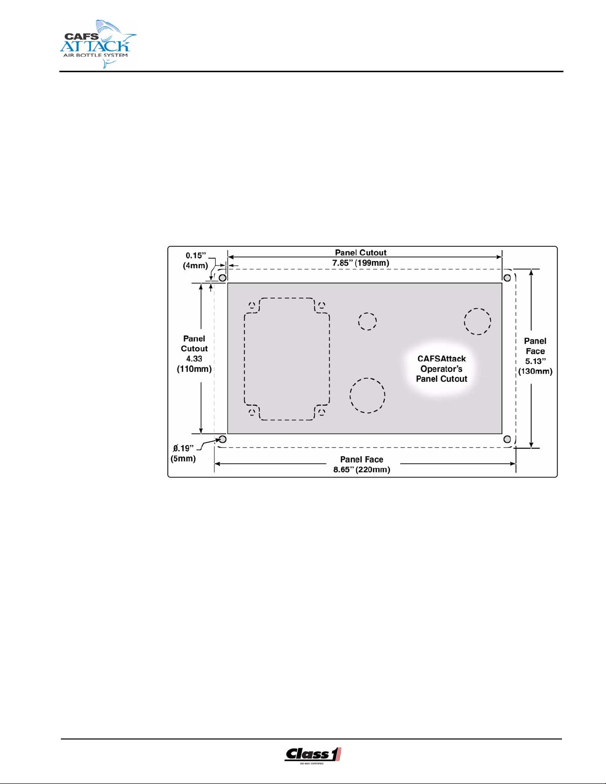
4.5 CAFSATTACK OPERATOR PANEL LAYOUT
(See Figure 4-4: “Operator’s Panel Layout Dimensions.”)
CAFS Air Bottle Installer/Operation Guide
p/n: 029-0020-85-0
Figure 4-4: Operator’s Panel Layout Dimensions
The following components are pre-mounted on the CAFSAttack operator’s
panel assembly:
❑ Inteli-Tank high pressure air level indicator - four (4) RED indicator lights
❑ HIGH pressure WARNING ! indicator light (YELLOW)
❑ On/Off air enable switch
❑ HIGH pressure shut-off valve and handle
❑ Quick-connect HIGH pressure air cylinder refill connection
Also see Figure 2-3: “CAFSAttack Operator Control Panel” on page 21.
1. Determine the location on the apparatus operator’s control panel for the
CAFSAttack operator’s panel assembly, with placard. This assembly
must be located at the main pump operator’s position in close proximity
to the FoamLogix system controls.
29
Page 30

❑ Installer Installation
2. Consideration must be given for routing the HIGH pressure tubing /
hoses and electrical harnesses. Make certain there is sufficient room
behind the assembly. If necessary, order a longer or shorter harness to
suit the location demands.
3. Modify the apparatus operator’s control panel to accept the CAFSAttack
operator’s panel and placard. (See Figure 4-4: “Operator’s Panel Layout
Dimensions.”) Use #10-24 screws and hardware to secure the panel the
apparatus control panel.
4. For plumbing, proceed to heading 4.7 “Plumbing” on page 31. For electrical, proceed to heading 4.8 “Electrical” on page 38.
4.6 SVS DISCHARGE MANIFOLD
30
Figure 4-5: Typical CAFSAttack SVS Discharge Manifold Assembly
CAFS Air Bottle Installer/Operation Guide
p/n: 029-0020-85-0
Page 31

Installer Installation ❑
The following components are pre-mounted on the SVS discharge manifold
assembly. (See Figure 4-5: “Typical CAFSAttack SVS Discharge Manifold
Assembly,” on page 30.)
❑ Electrically-operated Hale SVS valves, with valve position indicator.
See separate manual for description, installation and operation of the
SVS valves - Torrent SVS Valve Installation Operation and Maintenance
Manual, Hale p/n: 029-0020-90-0.
❑ Mixing chambers, includes one 2.0” (51 mm) mixer insert.
❑ Paddle wheel flow sensors (2).
1. The SVS Hale pre-manufactured, flange-mounted stainless steel discharge manifold is assembled and fully tested before leaving the factory.
When properly mounted, the flow sensor is on the side of the manifold
with one of the drain ports located at the bottom.
2. The flow sensor should point upwards slightly to allow drainage of water
and sediment. (See Figure 4-5: “Typical CAFSAttack SVS Discharge
Manifold Assembly,” on page 30.)
3. Mount the SVS discharge manifold assembly to the pump manifold discharge port using the gasket and hardware provided.
4. Apply a small amount of grease to the gasket before final installation,
then firmly tighten the four 7/16”-14 mounting bolts and torque to 33
ft.lbs. (45 N-m).
Note: The CAFS discharge connection from the SVS discharge manifold assembly is 2” (51 mm) Victaulic.
4.7 PLUMBING
IMPORTANT !
WHEN PLANING INTERCONNECTING PLUMBING LINES MAKE SURE THEY
ARE ROUTED BY THEIR SHORTEST MOST DIRECT ROUTE, STABILIZED
AGAINST EXCESSIVE VIBRATION AND ROUTED TO AVOID INTERFERENCE
WITH THE APPARATUS OPERATORS.
CONNECTING ENDS OF HYDRAULIC TUBING, IF USED, MUST BE FLARED.
USE THREAD SEALING COMPOUND, FOR EXAMPLE, LOCTITE PST OR
EQUIVALENT, ON ALL PLUMBING CONNECTIONS.
CAFS Air Bottle Installer/Operation Guide
p/n: 029-0020-85-0
A system block diagram is provided at the end of this manual.
31
Page 32

❑ Installer Installation
CAFSAttack Operator’s Control Panel
Figure 4-6: Typical HIGH Air Pressure Connections
WARNING !
THE CYLINDER PRESSURE LINES OPERATE AT PRESSURES UP TO 4,500
PSI (310 BAR). ALL FITTINGS, TUBING, ETC. SHOULD BE THE FLARED
TYPE AND MUST BE RATED FOR THE MAXIMUM SYSTEM OPERATING
PRESSURE.
IF HOSE IS REQUIRED, USE 3/8” (10MM) MINIMUM TO 1/2” (13MM), WIRE
REINFORCED HOSE, SUCH AS AEROQUIP FC350-16 FOR MAXIMUM AIR
FLOW.
1. A HIGH pressure air hose line (one each) must be plumbed from each DOT
air cylinder shut-off valve connection to the CAFSAttack operator panel shutoff valve inlet port. (See Figure 4-6: “Typical HIGH Air Pressure Connections.”)
32
CAFS Air Bottle Installer/Operation Guide
p/n: 029-0020-85-0
Page 33

Installer Installation ❑
It is preferred to run 3/8” (10 mm) high pressure tubing with flared ends for
connection to the appropriate fittings. Also see WARNING ! on page 32.
2. Ensure the hose or tubing is adequately secured against stresses, vibrations
and other conditions incident to being mounted on a fire apparatus and being
used in mobile service.
3. All materials used in the air system must be corrosion resistant or treated to
resist corrosion unless the finished product is in continual contact with a
noncorrosive lubricant.
4. Flexible hose must be installed to prevent cuts, abrasions, exposure to damage,
excessive temperatures, damage from loose equipment and excessive bending.
5. The installer/builder must provide the necessary plumbing hardware, i.e.,
fittings, tubing, etc. and make certain they conform to the maximum system
operating pressure of 4,500 psi (310 Bar).
6. Use a suitable sealing compound (for example, Loctite PST or equivalent) on
all fitting threads prior to installation.
7. Plumb a high pressure hose or hard tubing line from the outlet port of the
operator panel shut-off valve to the 3/4” (19 mm) fitting, reduced to 1/4” (6 mm)
tube fitting, at the IN port of the 4,500 PSI high pressure balancing regulator
valve. See WARNING ! on page 32. Also see Figure 4-7: “4,500 PSI HIGH
Pressure Balancing Regulator and Dome Connections” on page 34.
WARNING !
DO NOT TIGHTEN FITTINGS, GAGES, OR COMPONENTS WHILE IN A PRESSURIZED SYSTEM.
NEVER TURN THE REGULATOR OR VALVE BODY. INSTEAD HOLD THE
REGULATOR OR VALVE BODY AND TURN THE FITTING NUT.
IF A REGULATOR OR VALVE LEAKS OR MALFUNCTIONS, REMOVE IT FROM
SERVICE IMMEDIATELY.
8. An additional port must also be added for the tank level display air supply
pressure transducer. (See Figure 4-6: “Typical HIGH Air Pressure Connections,” on page 32.)
CAFS Air Bottle Installer/Operation Guide
p/n: 029-0020-85-0
33
Page 34

❑ Installer Installation
Figure 4-7: 4,500 PSI HIGH Pressure Balancing Regulator and Dome Connections
9. Plumb a 3/8”
(9.5 mm) tubing
line between the
bottom or dome
port on the balancing regulator valve
to the pump discharge for waterto-air operating
pressure balance.
(See Figure 4-8:
“Pump-to-Balancer Valve Dome
Connection.”)
Figure 4-8: Pump-to-Balancer Valve Dome Connection
34
CAFS Air Bottle Installer/Operation Guide
p/n: 029-0020-85-0
Page 35

Installer Installation ❑
Intake Air Pressure Gauge Layout Option
An “optional” high pressure gauge is available, Class1 p/n: ??, to provide
accurate intake air pressure monitoring (up to 7,500 PSI / 517 BAR) during
system operation and cylinder tank refill. (See Figure 4-9: “Typical Intake
Air Pressure Gauge Layout.”)
Figure 4-9: Typical Intake Air Pressure Gauge Layout
The gauge should be mounted in the area of the CAFSAttack operator’s
panel (tank refill connector) and plumbed before the air supply shut-off valve
intake. Provisions must also be made for the pressure transducer.
Also see WARNING ! note beginning on page 32. Use a suitable sealing
compound (for example, Loctite PST) on the fitting threads.
Low Pressure CAFS Connect (2)
A LOW or CAFS air pressure hose line (one each) and injection check
valves (one each) must be plumbed from each electrically-operated shut-off
valve connection to the CAFSAttack discharge manifold air intake port.
(See Figure 4-10: “Typical LOW Pressure CAFS Air Connections,” on page
36.)
1. The installer/builder must provide the necessary plumbing hose and hardware,
i.e., 3/4” (19 mm) fittings, tubing, etc. and make certain they conform to the
maximum CAFS system operating pressure of 150 PSI (10 BAR).
CAFS Air Bottle Installer/Operation Guide
p/n: 029-0020-85-0
35
Page 36

❑ Installer Installation
Figure 4-10: Typical LOW Pressure CAFS Air Connections
WARNING !
THE LOW PRESSURE CAFS LINES OPERATE AT PRESSURES OF APPROXIMATELY 150 PSI (10 BAR). ALL FITTINGS, TUBING, ETC. USED MUST BE
RATED FOR THE MAXIMUM CAFS SYSTEM DISCHARGE OPERATING
PRESSURE.
LOW PRESSURE LINES MUST ALSO BE ADEQUATE FOR OPERATING
TEMPERATURES FROM -30° F TO +140° F (-34° C TO +60° C).
2. Provisions must be made to include a check valve in each line to prevent water
/ foam solution from back-flowing and contaminating the air lines.
For best performance, the check valves (2) must be mounted right after the
main HIGH pressure shut-off valves. (See Figure 4-10: “Typical LOW Pressure
CAFS Air Connections.”)
36
CAFS Air Bottle Installer/Operation Guide
p/n: 029-0020-85-0
Page 37

Installer Installation ❑
3. A method for discharge draining / flushing (possible tee fitting) must also be
provided. (See heading “ Air Discharge Moisture Drain” on page 37.)
4. Use a suitable sealing compound (for example, Loctite PST) on all fitting
threads.
Air Discharge Moisture Drain
(See Figure 4-11: “Typical Discharge Drain.”)
The installer/
builder must supply individual
moisture drain
lines and valving
(3/4” / 9.5 mm),
along with all necessary DOT
approved tubing
(3/8” / 10 mm)
from the low pressure air inject
hose lines to prevent freezing in
cold weather.
When designing
the drain system
care must be
taken to prevent
Figure 4-11: Typical Discharge Drain
contamination of the air and water system with foam and vise versa. Use
appropriate check valves in the drain lines. Also see Figure 4-10: “Typical
LOW Pressure CAFS Air Connections” on page 36.
All Hale supplied tubing conforms to the color scheme
listed in Table 4-12: “Tubing
Size vs. Color.”
Use a suitable sealing com-
Line Size Color Use
1/4” (6.4mm) Black Air
1/4” (6.4mm) Green Air
1/4” (6.4mm) Red Air
pound (for example, Loctite
PST) on all fitting threads.
3/8” (9.5mm) Blue TPM
3/8” (9.5mm) Orange Manifold Drain
3/8” (9.5mm) Yellow Main Pump Drain
Table 4-12: Tubing Size vs. Color
CAFS Air Bottle Installer/Operation Guide
p/n: 029-0020-85-0
37
Page 38

❑ Installer Installation
CAFS Air LOW Pressure Gauge Layout Option
An “optional” numeric-display, low or CAFS air pressure gauge is available,
Class1 p/n: 91220001, to show the air pressure being delivered to the foam
discharge manifolds. (See Figure 4-13: “CAFS Air LOW Pressure Layout
Option,” on page 38.)
The gauge should be mounted in the area of the CAFSAttack operator’s
panel and plumbed in the system after the pressure balancing regulator
valve. Use 1/4” (6 mm) DOT approved tubing and 1/4” brass fittings.
Figure 4-13: CAFS Air LOW Pressure Layout Option
Use a suitable sealing compound (for example, Loctite PST) on all fitting
threads.
4.8 ELECTRICAL
A system electrical diagram is provided at the end of this manual. Refer to
this diagram for proper installation of the electrical components.
The Class1 CAFSAttack system is designed to be installed with a minimum
of electrical connections. A main harness cable assembly is provided with
each system to enable the flow sensor, electric valve motors and transducer
connections.
The system installer must supply primary power and ground wiring. Also
see Figure 4-16: “Primary CAFS Wire Harness” on page 41.
38
CAFS Air Bottle Installer/Operation Guide
p/n: 029-0020-85-0
Page 39

Installer Installation ❑
CAUTION !
❑ Review the “Safety” section of this manual, beginning on page 7, in
its entirety before proceeding with electrical connections.
❑ To prevent system damage or electrical shock the main power sup-
ply wire must be the last connection made.
❑ The cables provided with each CAFSAttack system contain
shielded assemblies.
NEVER attempt to shorten or lengthen these shielded cables.
If necessary order longer or shorter cables from Class1 to suit your
particular installation.
❑ The cables are indexed so they connect to the correct receptacle
one way only. The cables shipped with each CAFSAttack system
are tested at the factory with the specific unit. When making cable
connections DO NOT force mismatched connections as damage
can result, causing improper system operation.
❑ The system can only perform when the electrical connections are
sound.
Make sure each electrical connection is correct.
❑ Class1 CAFSAttack systems are designed for use on direct current,
negative (–) ground apparatus electrical systems only.
❑ Do not mount a radio transmitter or transmitter cables in direct or
close contact with the CAFSAttack unit.
❑ Before connecting cables, inspect the O-ring seal in the female con-
nector. If the seal washer is missing or damaged, water can enter
causing corrosion, resulting in possible system failure.
❑ Be careful when inserting connector halves to avoid bent pins or
pushed-back pins that do not make contact.
❑ The ground strap must be attached to the chassis frame. Ground-
ing to the body IS NOT acceptable.
❑ Always disconnect the power cable, ground straps, electrical wires
and cables from the control unit or other Hale FoamLogix equipment before electric arc welding at any point on the apparatus.
Failure to do so could result in a power surge through the unit that
could cause irreparable damage.
CAFS Air Bottle Installer/Operation Guide
p/n: 029-0020-85-0
❑ There are no user serviceable parts inside CAFSAttack system
electrical/electronic components. Opening of these components
(motor distribution box, smart-switch controller or control unit)
voids the warranty.
39
Page 40

❑ Installer Installation
Smart-Switch Controller - SPC (S1 and S2)
For the suggested panel installation and cutout dimensions see Figure 414: “Smart-Switch Controller Panel Cutout” on page 40.
Determine a location on the apparatus pump operator panel for the smartswitch controllers (2). Consideration must be given for routing the interconnecting cable from the controller to the foam discharge assembly and the
high pressure transducer assembly.
40
Figure 4-14: Smart-Switch Controller Panel Cutout
Once the SPC controllers are mounted on the
pump operator panel, attach the 10 pin AMP
connector on the cable assembly to the back of
the controller. (See Figure 4-15: “SPC Connector, Back View.”) Also see Figure 4-16: “Primary
CAFS Wire Harness” on page 41.
Notes: Ensure that the panel where the control
units are mounted has an adequate ground. For
stainless steel and vinyl coated panels a ground
strap, 1/2” (13 mm) wide, must be attached from
one of the four screws securing the controllers in
place to the frame of the apparatus to ensure adequate grounding.
Figure 4-15: SPC Connec-
tor, Back View
CAFS Air Bottle Installer/Operation Guide
p/n: 029-0020-85-0
Page 41

Installer Installation ❑
Add a service loop to avoid strain on the wires or connectors during body
and frame flex. Also see Figure 4-17: “Extra Cable Storage” on page 43.
CAFSAttack Main Wire Harness
The system installer must provide an extension main power and ground
wire cable for the Class1 CAFSAttack system. (See heading “ Primary
Power and Ground” on page 42.) Also see Figure 4-16: “Primary CAFS
Wire Harness.”
CAFS Air Bottle Installer/Operation Guide
p/n: 029-0020-85-0
Figure 4-16: Primary CAFS Wire Harness
Before connecting the cable harness, Class1 p/n: 112757, inspect the Oring seals of the female connectors. If a seal washer is missing or damaged, water can enter the connector causing pin and terminal corrosion,
resulting in possible system failure.
IMPORTANT !
THE POWER MUST BE FUSED FOR 12 VDC (OR OPTIONAL 24 VDC), MINIMUM 20 AMP. CIRCUIT TO MEET NFPA SPECIFICATIONS. USE MINIMUM 16
AWG TYPE SXL OR GXL (SAE J1128) WIRE.
DO NOT CONNECT POWER SUPPLY HARNESS TO A “LOAD SHEDDING
SYSTEM.
41
Page 42

❑ Installer Installation
WHEN PLANING CABLE RUNS MAKE SURE THE WIRES ARE ROUTED BY
THEIR SHORTEST MOST DIRECT ROUTE, STABILIZED AGAINST EXCESSIVE
VIBRATION AND ROUTED TO AVOID INTERFERENCE WITH THE APPARATUS
OPERATORS.
For complete cable design of the standard harness (Class1 p/n: 112757)
and for the Triple Discharge Option harness (Class1 p/n: 114810), also see
Section 8, heading “Drawing / Manual Package” on page 67.
Primary Power and Ground
PREVENT CORROSION OF POWER AND GROUND CONNECTIONS BY SEALING THESE CONNECTIONS WITH SILICONE SEALANT.
IMPORTANT - continued !
CAUTION !
DO NOT CONNECT THE MAIN POWER LEAD TO SMALL LEADS THAT ARE
SUPPLYING SOME OTHER DEVICE, SUCH AS A LIGHT BAR OR SIREN. THE
CAFSATTACK SYSTEM REQUIRES ?? AMP MINIMUM CURRENT.
USE MINIMUM 14 AWG TYPE SXL/GXL (SAE J1128) WIRE.
Primary electrical power must be supplied directly from the battery, the battery master disconnect switch or solenoids to the CAFSAttack harness,
connector #13.
❑ RED................... Power
❑ BLACK .............. Ground
The primary power connection must be made so that power is supplied to
the CAFSAttack system when the main apparatus electrical system is energized. This ensures immediate operation when the operator places the
apparatus in PUMP mode, and to prevent battery power drain when the
apparatus is not running.
Be sure the CAFSAttack system is grounded to the chassis.
When making the ground connections make sure lugs are soldered to the
strap ends for trouble free connections. Seal all connection against
corrosion.
42
CAFS Air Bottle Installer/Operation Guide
p/n: 029-0020-85-0
Page 43

Installer Installation ❑
RFI / EMI
A 100% electrically shielded main cable harness is provided with the Class1
CAFSAttack system to eliminate the potential problem of RFI / EMI.
Proper installation of system components and cables, along with
proper grounding, limits radio interference caused by the CAFSAttack
system. Additionally, make sure
radio cables and hardware are not
located in the immediate area
where the CAFSAttack system is
mounted.
Making round coils of extra control
and flow sensor cables in the pump
compartment can act as an
antenna. While the control and
flow sensor cables cannot be shortened, various lengths of cable are available to minimize the “extra” cable in
the apparatus. (See Figure 4-17: “Extra Cable Storage.”)
Figure 4-17: Extra Cable Storage
When routing control and flow sensor cables take care to avoid routing them
next to antenna wires, radio power lines and radio components.
When there is extra cable, double the cable back on itself and secure with
plastic wire ties in a flat bundle instead of making a round coil. (See Figure
4-17: “Extra Cable Storage,” on page 43.)
Flow Sensor Connections (FM1 and FM2)
The main cable harness (connectors #1 and #7) connect to the 3-pin connector on the flow sensors. (See Figure 4-16: “Primary CAFS Wire Harness,” on page 41.)
NEVER attempt to shorten or lengthen these shielded cables. If necessary
order longer or shorter cables from Class1 to suit your particular installation
needs. Wire used is minimum 18 AWG type SXL/GXL (SAE J1128) Wire.
Air Supply Valve, Electric Motor (MV2)
Connect the main cable harness (connectors #2 and #8) to the 3-pin connectors on the air supply electric motors. (See Figure 4-16: “Primary CAFS
Wire Harness,” on page 41.)
CAFS Air Bottle Installer/Operation Guide
p/n: 029-0020-85-0
43
Page 44

❑ Installer Installation
NEVER attempt to shorten or lengthen these shielded cables. If necessary
order longer or shorter cables from Class1 to suit your particular installation
needs. Wire used is minimum 18 AWG type SXL/GXL (SAE J1128) Wire.
Discharge Valve, Electric Motor (MV1)
Connect the main cable harness (connectors #3 and #9) to the ?-pin con-
nectors on the discharge air valve electric motors. (See Figure 4-16: “Primary CAFS Wire Harness,” on page 41.)
NEVER attempt to shorten or lengthen these shielded cables. If necessary
order longer or shorter cables from Class1 to suit your particular installation
needs. Wire used is minimum 16 AWG type SXL/GXL (SAE J1128) Wire.
On/Off Switch (SA3), Operator Control Panel
(See Figure 4-18: “On/Off Switch Connection.”)
Connect the red and
white wires from the
FoamLogix main
cable harness to the
connectors on the
back of the CAFS on/
off switch. (See Figure 4-16: “Primary
CAFS Wire Harness,”
on page 41.)
Use minimum 16
AWG type SXL/GXL
(SAE J1128) wire.
44
Figure 4-18: On/Off Switch Connection
CAFS Air Bottle Installer/Operation Guide
p/n: 029-0020-85-0
Page 45

Start Up Check List ❑
4.9 INSTALLATION AND DELIVERY CHECK LIST
After the CAFSAttack system is installed, use the following check list to verify installation and ensure proper system startup when the apparatus is
delivered to the end user.
Installation
Date Initials
_______ _______ ❑ CAFSAttack system is properly installed. See Section 4
“Installation - Retrofit Full Size Pumper” on page 25.
❑ Review previous Section 4.7 “Plumbing,” beginning on page
31.
❑ Review previous Section 4.8 “Electrical,” beginning on page
38.
❑ Also see heading “Start Up Check List” on page 46.
_______ _______ ❑ FoamLogix system calibration and operation checked. See
separate manual provided.
❑ FoamLogix Model 2.1A Installation and Operation Manual,
Hale p/n: 029-0020-74-0
❑ FoamLogix Model 3.3 and 5.0 Installation and Operation Man-
ual, Hale p/n: 029-0020-68-0
Delivery
Date _______ Initials
_______ ______ ❑ DOT Air cylinders proper filled (charged).
_______ _______ ❑ CAFSAttack shut-off valve is in the OFF (O) position (valve
handle in the horizontal position).
_______ _______ ❑ CAFSAttack WET/DRY smart-switch presets set to end user
specification. See Section 5a.1, heading “Smart-Switch calibration” on page 51.
_______ _______ ❑ Proper CAFSAttack system operation demonstrated to end
user in accordance with manual procedures. See Section
5a.1, heading “Starting CAFSAttack” on page 54.
_______ _______ ❑ End user trained in proper operation of the CAFSAttack sys-
tem in accordance with manual procedures. See Section 5a.1,
heading “Starting CAFSAttack” on page 54.
_______ _______ ❑ Warranty registration card filled out by end user and mailed to
Hale Products Inc.
_______ _______ ❑ Two copies of Installation and Operation manual provided to
end user.
CAFS Bottled-Air Operator/s Guide
p/n: 029-0020-85-0
45
Page 46

❑ Start Up Check List
4.10 START UP CHECK LIST
Before energizing the apparatus and the CAFSAttack system for the first
time make sure the following items are checked:
Electrical
❑ Main cable harness connections are correct and tight. (See Figure 4-16:
“Primary CAFS Wire Harness,” on page 41.)
❑ All cables and wires are secured and protected from damage during
operation.
❑ Flow sensor cable properly connected to main cable harness (C1 and
C7).
❑ Control and flow sensor cables properly folded and secured; radio anten-
nas, power lines and equipment away from cables.
❑ The system is properly grounded using flat ground strap.
❑ Correct voltage provided. Direct current, negative (–) ground.
❑ Adequate current, ?? AMPS minimum, available. Main power direct to
battery, battery switch or solenoid without primer or other accessories
tied in.
❑ Primary electrical and ground connections tight and protected from cor-
rosion with silicone sealant.
❑ Splices in wires sealed from moisture using adhesive filled heat shrink
tubing.
Make sure the FoamLogix system is energized when either the CAFSAttack smart-switch WET or DRY button is pressed.
Air and Water
❑ All HIGH pressure air lines are the proper size and type and all connec-
tions are tight.
46
WARNING !
ONCE THE AIR CYLINDERS ARE FULLY CHARGED AND THE SYSTEM IS
ENERGIZED, ALL HIGH PRESSURE LINES BETWEEN THE CYLINDER SHUTOFF VALVES AND THE PRESSURE BALANCING REGULATOR VALVES ARE
EXPOSED TO HIGH PRESSURE (4,500 PSI / 310 BAR).
CAFS Bottled-Air Operato r/s Guide
p/n: 029-0020-85-0
Page 47

Start Up Check List ❑
WARNING ! - continued
THE HIGH PRESSURE SIDE IS BLED (PRESSURE RELIEVED) BY FIRST MAKING SURE THE CYLINDER SHUT-OFF VALVE IS FULLY CLOSED. THEN
SLIGHTLY LOOSENING THE HOSE FITTING NUT AT THE CYLINDER SHUTOFF VALVE UNTIL YOU HEAR AIR ESCAPING FROM THE FITTING. AN
ALTERNATE METHOD IS TO INSTALL AND SHUT-OFF VALVE IN AN ACCESSIBLE AREA IN THE HIGH PRESSURE LINE. ALSO SEE HEADING “RELIEVING HIGH PRESSURE” ON PAGE 59.
❑ All LOW discharge pressure air lines are the proper size and type and all
connections are tight.
WARNING !
ONCE THE CYLINDERS ARE FULLY CHARGED AND THE SYSTEM IS ENERGIZED, THE DISCHARGE (LOW) PRESSURE LINES ARE EXPOSED TO LOW
PRESSURE (APPROXIMATELY 150 PSI / 10 BAR).
THE DISCHARGE LINES ARE BLED (PRESSURE RELIEVED) BY OPENING
THE CONDENSATION DRAIN VALVES.
❑ The water line from the midship pump the pressure balancing regulator
valve dome port is the proper size and type and the connections are
tight.
❑ Flow sensor mounted with flow arrow in the correct direction for water
flow.
❑ Check valves are properly mounted in air lines. (See Figure 4-10: “Typi-
cal LOW Pressure CAFS Air Connections,” on page 36.) Also see Figure
4-5: “Typical CAFSAttack SVS Discharge Manifold Assembly” on page
30.
❑ Air filter/strainer mounted for proper air flow direction.
❑ All hoses are free of kinks and sharp bends. No sharp bends exist that
can trap air in the system.
❑ Condensation discharge air line connections correct and tight.
❑ Discharge piping is hydro-tested in accordance with NFPA / UL
requirements.
❑ Air cylinder shut-off valve on the CAFSAttack operator’s panel is in the
CLOSED (O) position.
CAFS Bottled-Air Operator/s Guide
p/n: 029-0020-85-0
❑ The CAFSAttack ENABLE on/off switch is in the OFF (O) position.
47
Page 48

❑ Start Up Check List
4.11 SYSTEM INSTALLER START-UP
When energizing the CAFSAttack system at the system installer facility for
the first time the following procedures shall be used.
Initial System Power Check
1. To check the HIGH pressure lines, SLOWLY open the cylinder shut-off
valve to gradually pressurize the HIGH pressure side of the system.
(See Figure 4-1: “CAFSAttack System Overview,” on page 25.)
2. Check each connection for leaks.
If a leak is detected immediately CLOSE the cylinder shut-off valve,
bleed pressurized air from the system and repair the leak before returning the system to operation. See Section 6.3, heading “Relieving HIGH
PRessure” on page 59.
3. Repeat preceding Steps 1 and 2.
System Operation Check
After initial system power-up, CAFSAttack, and the FoamLogix systems
must be checked.
For FoamLogix
See the specific FoamLogix manual used in your CAFSAttack system:
❑ FoamLogix Model 2.1A Installation and Operation Manual, Hale p/n:
029-0020-74-0
❑ FoamLogix Model 3.3 and 5.0 Installation and Operation Manual, Hale
p/n: 029-0020-68-0
Follow the procedures outline in the separate FoamLogix manual,
headings:
❑ Start Up Check List
48
❑ Installation and Delivery Check List
❑ System Installer Start-Up
❑ User (Setup) Calibration
CAFS Bottled-Air Operato r/s Guide
p/n: 029-0020-85-0
Page 49

For CAFSAttack
? ? ?
Start Up Check List ❑
CAFS Bottled-Air Operator/s Guide
p/n: 029-0020-85-0
49
Page 50

❑ Start Up Check List
Notes
____________________________________________________________________
____________________________________________________________________
____________________________________________________________________
____________________________________________________________________
____________________________________________________________________
____________________________________________________________________
____________________________________________________________________
____________________________________________________________________
____________________________________________________________________
____________________________________________________________________
____________________________________________________________________
____________________________________________________________________
____________________________________________________________________
____________________________________________________________________
____________________________________________________________________
____________________________________________________________________
____________________________________________________________________
____________________________________________________________________
____________________________________________________________________
____________________________________________________________________
____________________________________________________________________
____________________________________________________________________
____________________________________________________________________
____________________________________________________________________
____________________________________________________________________
____________________________________________________________________
____________________________________________________________________
____________________________________________________________________
____________________________________________________________________
____________________________________________________________________
____________________________________________________________________
____________________________________________________________________
____________________________________________________________________
____________________________________________________________________
____________________________________________________________________
50
CAFS Bottled-Air Operato r/s Guide
p/n: 029-0020-85-0
Page 51

5 Preset calibration
This section details the calibration process for the Smart-Switch controllers, Presets 1 and 2.
When the apparatus is delivered to the end user facility the foam tank(s) must be
filled with the specified foam concentrate(s) intended for use. Make sure the proper
foam concentrate is placed into the correct tank. The system must then be
adjusted to operate with the end user foam concentrate(s) for best accuracy.
Note: For FoamLogix calibration, see FoamLogix Model 2.1A Installation and
Operation Manual, Hale p/n: 029-0020-74-0; or FoamLogix Model 3.3 and 5.0
Installation and Operation Manual, Hale p/n: 029-0020-68-0.
5A.1 SMART-SWITCH CALIBRATION
Preset Calibration / Operation ❑
(See Figure 5-1: “Smart-Switch Calibration Overview.”) The calibration process allows easy adjustment of the air flow electrically-controlled valves to
established presets when the WET or DRY button is pressed. The preset
settings (Preset 1 - DRY and Preset 2 - WET) are established between the
end user and the installer/builder at time of time of delivery and customer
training.
CAFS Bottled-Air Operator/s Guide
p/n: 029-0020-85-0
Figure 5-1: Smart-Switch Calibration Overview
51
Page 52

❑ Preset Calibration / Operation
Recalibration may be required ONLY after major repairs or component
changes are made to the CAFSAttack system or when a different viscosity
of foam concentrates is needed (wetter or dryer).
IMPORTANT !
THERE IS A SMART-SWITCH CONTROLLER FOR EACH AIR CYLINDER.
THEREFORE BOTH NEED TO BE ADJUSTED, ALTHOUGH THEY CAN BE
ADJUSTED DIFFERENTLY FOR INDIVIDUAL CAFS RESULTS.
FOR EXAMPLE, ONE COULD BE SET TO DISCHARGE A “WET” QUICK DRAINING FOAM BLANKET; WHILE THE OTHER COULD DISCHARGE A “DRY,” SHAVING CREAM-LIKE, FOAM FOR EXPOSURE PROTECTION.
To calibrate a WET consistency...
1. Energize the apparatus to provide power to the operator’s panel.
2. Supply water to engage and operate the pump at an appropriate discharge pressure.
3. Set the CAFSAttack ENABLE switch to the ON (I) position. Also see
Figure 2-3: “CAFSAttack Operator Control Panel” on page 21.
❑ The background indicator lights on the smart-switch controllers illumi-
nate. (See Figure 5-1: “Smart-Switch Calibration Overview,” on page
51.)
❑ The intelli-tank air level display illuminates to show the air-remaining
level in the cylinders. (See Figure 2-3: “CAFSAttack Operator Control
Panel,” on page 21.)
Note: The air level indicator lights are an accumulation of both cylinders. See
separate manual, located at the back of this manual, for additional information.
4. Set the air bottle valve handle to the OPEN (I) position. Also see Figure
2-3: “CAFSAttack Operator Control Panel” on page 21.
5. Press and release the WET Button.
52
❑ The WET button LED flashes.
❑ The valve position bar graph indicator LEDs illuminate to indicate the
relative position of the discharge valve (the more bars illuminated indicates a WETTER consistency).
❑ The FoamLogix display controller is activated in preparation to flow
foam when water flow is detected.
CAFS Bottled-Air Operato r/s Guide
p/n: 029-0020-85-0
Page 53

Preset Calibration / Operation ❑
6. Begin discharging CAFS in accordance with departmental or locality
regulations. If you are satisfied with the results, continue with Step 8. to
store the setting.
7. Use the OPEN and CLOSE buttons on the smart-switch to change the
CAFS consistency to the desired WETNESS (press OPEN for WETTER; press CLOSE for DRYER consistency).
8. Once the required consistency is achieved, press and HOLD the WET
button for about ten (10) seconds to store (program) this new Preset 2
setting. RELEASE the button when the smart-switch flashes once.
To calibrate a DRY consistency...
1. Energize the apparatus to provide power to the operator’s panel.
2. Supply water to engage and operate the pump at an appropriate discharge pressure.
3. Set the CAFSAttack ENABLE switch to the ON (I) position. Also see
Figure 2-3: “CAFSAttack Operator Control Panel” on page 21.
❑ The background indicator lights on the smart-switch controllers illumi-
nate. (See Figure 5-1: “Smart-Switch Calibration Overview,” on page
51.)
❑ The intelli-tank air level display illuminates to show the air-remaining
level in the cylinders. (See Figure 2-3: “CAFSAttack Operator Control
Panel,” on page 21.)
Note: The air level indicator lights are an accumulation of both cylinders. See
separate manual, located at the back of this manual, for additional information.
4. Set the air bottle valve handle to the OPEN (I) position. Also see Figure
2-3: “CAFSAttack Operator Control Panel” on page 21.
5. Press and release the DRY Button.
❑ The DRY button LED flashes.
CAFS Bottled-Air Operator/s Guide
p/n: 029-0020-85-0
❑ The valve position bar graph indicator LEDs illuminate to indicate the
relative position of the discharge valve (the less bars illuminated indicates a DRYER consistency).
❑ The FoamLogix display controller is activated in preparation to flow
foam when water flow is detected.
53
Page 54

❑ Preset Calibration / Operation
6. Begin discharging CAFS in accordance with departmental or locality
regulations. If you are satisfied with the results, continue with Step 8. to
store the setting.
7. Use the OPEN and CLOSE buttons on the smart-switch to change the
CAFS consistency to the desired DRYNESS (press OPEN for WETTER; press CLOSE for DRYER consistency).
8. Once the required consistency is achieved, press and HOLD the DRY
button for about ten (10) seconds to store (program) this new Preset 1
setting. RELEASE the button when the smart-switch flashes once.
5a Basic operation
IMPORTANT !
CLASS 1 RECOMMENDS ADDITIONAL TRAINING IN STRATEGY AND TACTICS OF USING CAFS BY THE AUTHORITY HAVING JURISDICTION. THIS
MANUAL IS A SIMPLE GUIDE TO CAFSATTACK SYSTEM. ADDITIONAL CAFS
OPERATION TRAINING IS REQUIRED.
BEFORE OPERATING YOUR NEW CAFSATTACK SYSTEM, PLEASE REVIEW
THIS MANUAL AND THE FOAMLOGIX MANUAL (PROVIDED WITH THE FOAMLOGIX SYSTEM) IN THEIR ENTIRETY. THE OPERATOR IS RESPONSIBLE
FOR OBSERVING ALL INSTRUCTIONS, SAFETY AND SPECIFIC DEPARTMENTAL OR LOCAL REGULATIONS IN HIS OR HER DAILY ROUTINE RELATED TO
THE USE OF THIS EQUIPMENT.
5A.1 STARTING CAFSATTACK
1. Energize the apparatus to provide power to the operator’s panel.
2. Supply water to engage and operate the pump at an appropriate discharge pressure.
3. Set the CAFSAttack ENABLE switch to the ON (I) position. Also see
Figure 2-3: “CAFSAttack Operator Control Panel” on page 21.
54
❑ The background indicator lights on the smart-switch controllers illumi-
nate. (See Figure 5-1: “Smart-Switch Calibration Overview,” on page
51.)
CAFS Bottled-Air Operato r/s Guide
p/n: 029-0020-85-0
Page 55

Preset Calibration / Operation ❑
❑ The intelli-tank air level display illuminates to show the air-remaining
level in the cylinders. (See Figure 2-3: “CAFSAttack Operator Control
Panel,” on page 21.)
Note: The air level indicator lights are an accumulation of both cylinders. See
separate manual, located at the back of this manual, for additional information.
IMPORTANT !
KEEP IN MIND THAT THERE IS A SMART-SWITCH CONTROLLER FOR EACH
AIR CYLINDER. THEREFORE BOTH NEED TO BE ADJUSTED, ALTHOUGH
THEY CAN BE ADJUSTED DIFFERENTLY FOR INDIVIDUAL CAFS RESULTS.
FOR EXAMPLE, ONE COULD BE SET TO DISCHARGE A
“WET” QUICK
DRAINING FOAM BLANKET; WHILE THE OTHER COULD DISCHARGE
A “DRY,” SHAVING CREAM-LIKE, FOAM FOR EXPOSURE PROTECTION.
4. Set the air bottle valve Handle to the OPEN (I) position. Also see Figure
2-3: “CAFSAttack Operator Control Panel” on page 21.
5. Press and release the desired foam consistency button - either WET or
DRY.
❑ The selected button LED flashes.
❑ The valve position bar graph indicator LEDs illuminate to indicate the
relative position of the discharge valve (the less bars illuminated indicates a DRYER consistency; to more bars, a WETTER consistency).
❑ The FoamLogix display controller is activated in preparation to flow
foam when water flow is detected.
6. Begin discharging CAFS in accordance with departmental or locality
regulations.
CAFS Bottled-Air Operator/s Guide
p/n: 029-0020-85-0
CAUTION !
COLD WEATHER ENVIRONMENTS (TEMPERATURES AT OR NEAR 32° F
(0° C) CAN CAUSE SOME SYSTEM COMPONENTS TO FREEZE AND
RESTRICT AIR FLOW. COMPONENTS MUST BE THAWED BEFORE CONTINUING CAFS OPERATION.
55
Page 56

❑ Preset Calibration / Operation
5A.2 SHUTTING-DOWN CAFSATTACK
IMPORTANT !
WHEN CAFS OPERATION IS COMPLETE, SET THE AIR BOTTLE VALVE HANDLE TO THE CLOSE (O) POSITION.
DANGER !
NEVER FULLY EMPTY THE CAFSATTACK AIR CYLINDERS. ALWAYS MAINTAIN POSITIVE PRESSURE IN THE CYLINDERS TO PREVENT MOISTURE
AND/OR DIRT CONTAMINATION. AN INDICATION OF A “LOW” CHARGE IN
TO AIR BOTTLES IS WHEN THE BOTTOM LIGHT ON THE INTELLI-TANK DISPLAY FLASHES.
NEVER LEAVE THE AIR BOTTLE SHUT-OFF “OPENED” WHEN THE SYSTEM
IS NOT IN OPERATION.
5A.3 EMERGENCY SHUT-DOWN
Should an emergency shut-down be required in the event of a:
❑ System electrical power loss
❑ Electrically-operated valve malfunction - sticking valve that does not
open or close properly, valve opened when it should be closed providing
air in lines when not wanted, etc.
❑ Loss of foam - empty tanks, valve malfunction, FoamLogix system mal-
function, etc.
❑ CAFS is always enabled, does not shut-down
❑ Any other system malfunction that produces a dangerous operating
condition
1. Manually shut-off the air supply to the system - turn the CAFSAttack air bottle valve, on the operator’s control panel, to the
CLOSE position (O).
2. Set the CAFS ENABLE switch, on the operator’s control panel, to
OFF (O).
3. Close the air bottle shut-off valves on each cylinder.
56
CAFS Bottled-Air Operato r/s Guide
p/n: 029-0020-85-0
Page 57

6 Routine maintenance
6.1 MAINTENANCE PROCEDURES
After each use
❑ Inspect wiring, hoses, flow sensors and connections for tightness, cor-
rosion, leaks and/or damage. (See Section 4, heading 4.7 “Plumbing,”
on page 31.) Also see Section 4, heading “Electrical” on page 38.
❑ Verify status of the CAFSAttack air filter element. See heading 6.2
“Replace Filter Element” on page 58.
❑ Clean inspect the CAFSAttack system for after each use.
Routine Maintenance ❑
❑ Verify status (charge) of the air-bottle cylinders. (See Section 2, head-
ing “Intelli-Tank Air Level Indicator,” on page 22.). Refill as needed.
(See Section 2, heading “Air Bottle FILL Coupling,” on page 22.)
❑ Flush the foam pump if a non-approved foam concentrate is used.
Also see “Appendix B: Foam Concentrate Compatibility” on page 61.
❑ See your specific FoamLogix manual, provided with the system, for
additional maintenance procedures.
Monthly
❑ See your specific FoamLogix manual, provided with the system, for
maintenance procedures.
❑ Verify air flow calibration. (See Section 5 “Preset calibration,” on page
51.)
❑ Visually and functionally inspect the CAFSAttack system for leaks and
proper system operation.
❑ Ensure that all shut-off valves and switches function properly.
CAFS Bottled-Air Operator/s Guide
p/n: 029-0020-85-0
Every Two (2) Months
❑ See your specific FoamLogix manual, provided with the system, for
maintenance procedures.
57
Page 58

❑ Routine Maintenance
❑ If an approved foam concentrate has been left in the system, operate
the FoamLogix to move the foam concentrate and prevent jelling.
Annually
❑ See your specific FoamLogix manual, provided with the system, for
maintenance procedures.
❑ Verify foam feedback calibration.
6.2 REPLACE FILTER ELEMENT
A visual pressure indicator
(plunger) shows the contaminated build up to alert the
operator when the filter element must be changed. (See
Figure 6-1: “Filter Pressure
Contamination Gauge.”)
The element must be changed
when the indicator plunger
reaches to the top of the sight
glass.
Figure 6-1: Filter Pressure Contamination
Gauge
WARNING !
THE FILTER SEES HIGH PRESSURE OF 4,500 PSI (310 BAR), WHICH MUST
BE RELIEVED BEFORE ATTEMPTING TO CHANGE THE FILTER ELEMENT.
TO RELIEVE PRESSURE, SEE HEADING 6.3 “RELIEVING HIGH PRESSURE”
ON PAGE 59.
1. Shut-down the CAFSAttack system. (See Section 5a.2 “Shutting-down
CAFSAttack,” on page 56.)
2. Relieve the system HIGH pressure. See heading 6.3 “Relieving HIGH
PRessure” on page 59.
3. Using an appropriate wrench (1.5” / 38 mm hex), unscrew the element
casing and remove the filter element.
4. Clean the case and the sealing area around the filter housing base,
insert the replacement element (Class1 p/n: ????????).
58
CAFS Bottled-Air Operato r/s Guide
p/n: 029-0020-85-0
Page 59

Routine Maintenance ❑
5. Apply light lubricant (oil) to the O-ring seal and thread and tighten the
case to the housing base.
6.3 RELIEVING HIGH PRESSURE
DANGER !
ONCE THE AIR CYLINDERS ARE FULLY CHARGED AND THE SYSTEM IS
ENERGIZED, ALL HIGH PRESSURE LINES BETWEEN THE CYLINDER SHUTOFF VALVES AND THE PRESSER BALANCING REGULATOR VALVES,
INCLUDING THE AIR FILTER, ARE EXPOSED TO HIGH PRESSURES (4,500
PSI / 310 BAR).
DO NOT PERFORM ANY SERVICE TO THE HIGH PRESSURE SIDE UNTIL THE
SYSTEM PRESSURE IS RELIEVED.
1. The HIGH pressure side is bled (pressure relieved) by FIRST making
sure the cylinder shut-off valves are FULLY CLOSED and the system is
shut-down. (See Section 5a.2 “Shutting-down CAFSAttack,” on page
56.)
2. Then slightly loosening
the hose fitting nut a few
turns at the cylinder shutoff valve until you begin
to hear air escaping from
the fitting. (See Figure 62: “Relieving HIGH Pressure.”)
An alternate method is to
install a shut-off valve in
an accessible area in the
HIGH pressure line.
3. When ALL pressure is
relieved from the system
(air escaping can no
longer be heard, or down
to zero {0} PSI / BAR) it is
then safe to service the
HIGH pressure system.
Figure 6-2: Relieving HIGH Pressure
CAFS Bottled-Air Operator/s Guide
p/n: 029-0020-85-0
4. Once pressure is relieved, fully tighten the cylinder hose fitting nut.
59
Page 60

❑ Routine Maintenance
Notes
______________________________________________________________
______________________________________________________________
______________________________________________________________
______________________________________________________________
______________________________________________________________
______________________________________________________________
______________________________________________________________
______________________________________________________________
______________________________________________________________
______________________________________________________________
______________________________________________________________
______________________________________________________________
______________________________________________________________
______________________________________________________________
______________________________________________________________
______________________________________________________________
______________________________________________________________
______________________________________________________________
______________________________________________________________
______________________________________________________________
______________________________________________________________
______________________________________________________________
______________________________________________________________
______________________________________________________________
______________________________________________________________
______________________________________________________________
______________________________________________________________
______________________________________________________________
______________________________________________________________
______________________________________________________________
______________________________________________________________
______________________________________________________________
______________________________________________________________
60
CAFS Bottled-Air Operato r/s Guide
p/n: 029-0020-85-0
Page 61

Hale Foam Concentrate Compatibility Chart ❑
Appendix B: Foam Concentrate Compatibility
The following foam concentrates are approved for use in Hale Foam Proportioning Systems. The Class “A” foam concentrates are approved for use in all Hale
Foam Proportioning Systems (i.e., Hale FoamLogix 5.0, 3.3, 2.1 and Hale V
Series).
Type of Foam
Concentrate
Manufacturer Brand Name
CLASS “A” FOAM
US Forestry Service
Approved
Reference * and **
Note:
This list of compactible
foam concentrate is
updated regularly.
For latest information see
www.haleproducts.com.
* For use in FoamLogix Model 5.0, 3.3, 2.1 and Hale V-Series.
** USFS approved foams have been tested for corrosion and biodegradability toxicity by the US Forest
Service in addition to the Hale testing described on page 63.
Ansul Silvex Class “A” Foam Concentrate
Kidde Fire Fighting /
National Foam
Kidde Fire Fighting /
National Foam
Kidde Fire Fighting /
National Foam
Monsanto PhosCheck WD881
Chemonics Fire-Trol Fire Foam 103
Chemonics Fire-Trol Fire Foam 104
3M Light Water FT-1150
ForeXpan S (0.1% - 1.0%)
Hi Combat Class “A” 91st Defense Class “A” Cold Water
Foam)
Knock-Down
Non US Forestry Service Approved
Reference *
www.haleproducts.com/products/foa m
Rev. -B, 01/2006
Chemguard Class “A” Plus
Unifoam Co. Lid. UniA 1%
3M Light Water SFFF
Kidde Fire Fighting /
National Foam
Kidde Fire Fighting /
Angus Foam
Table B-1: Hale Foam Class “A” Concentrate Compatibility
Responder
FirePower Class “A”
61
Page 62

❑ Hale Foam Concentrate Compatibility Chart
Type of Foam
Concentrate
Manufacturer Brand Name
CLASS “B” FOAM
* The Class “B” Foam, Specialty foam and Fire Fighting Additive Concentrates are approved for use in FoamLogix
Models 5.o and 3.3 Foam Proportioning System only.
AFFF Alcohol Resistant
Concentrate
Reference *
Note:
This list of compactible
foam concentrate is
updated regularly.
For latest information see
www.haleproducts.com.
AFFF
3M
Ansul 3 x 3 Low Viscosity Alcohol Resistant Concentrate
ChemGuard AR 3% - 6% (p/n: CAR36P)
ChemGuard Ultraguard 1% - 3% (p/n: C-133)
ChemGuard AR-AFFF 3% x 3% (p/n: C-333)
Kidde Fire Fighting /
Angus Foam
Kidde Fire Fighting /
Angus Foam
Kidde Fire Fighting /
Angus Foam
US Foam
US Foam
Kidde Fire Fighting /
National Foam
3% Alcohol Type AFFF Concentrate
(p\n: 98-0211-6573-7)
Alcohoseal 3 x 3
Universal Gold 3% AR-AFFF
Universal Gold, 1% - 3% AR-AFFF
1% 03% Alcohol Resistant AFFF
(p/n: US-AR13)
1% - 3% Alcohol Resistant AFFF
(p/n: US-FCAR36)
1% Aero-Water
62
SPECIALTY FOAM CONCENTRATES
Protein
Kidde Fire Fighting /
National Foam
Chemonics Durra Foam 3%
Terra Foam 3% CF
FIRE FIGHTING WATER ADDITIVE
Hazard Control
Technologies Inc.
SPL Control LLC
Table B-2: Hale Foam Class “B” Concentrate Compatibility
F-500 (1%, 3%, 6%)
Pyrosolv (FF Agent - 6% Solution
(p/n: 72038, MSDS#)
www.haleproducts.com/products/foam
Rev. -B, 01/2006
Page 63

Hale Foam Concentrate Compatibility Chart ❑
Reference
The preceding foam concentrates have been tested by Hale Products to
ensure compatibility with Hale FoamLogix models 5.0 and 3.3 Foam Proportioning Systems. These chemicals were run for several hundred hours
over several months to make sure they do not harm the Foam System. This
list is solely intended to assist the end user in selection of foam concentrate(s) compatible with a Hale FoamLogix Model 5.0 and 3.3 and is not a
determination of the fire fighting effectiveness of one product over another.
Always consult with NFPA standards, U.L. Listings, Federal, State, and local
regulations pertaining to application and environmental regulations before
selecting a foam concentrate. (Refer to FoamLogix User Manual for additional information.)
Many fire fighting foam chemical manufacturers have specific instructions
on handling and use of their products including, but not limited to, shelf life,
tank life, and intervals between use. Always follow manufacturer’s instructions for use.
This Appendix applies to Hale FoamLogix foam pumps built after April 17,
1997. For Hale FoamMaster foam pumps built prior to April 17, 1997, refer
to Bulletin 650, Rev-2.
If a particular foam concentrate you wish to use does not appear on this list,
please contact your Hale representative for information concerning compatibility with Hale FoamLogix Model 5.0 or 3.3 Foam Proportioning Systems.
As further testing is completed, Hale Products Inc. updates this list and
expands capabilities and features to keep the Hale FoamLogix the best system available for all fire fighting.
Revised 01/05/2006
www.haleproducts.com/products/foa m
Rev. -B, 01/2006
63
Page 64

❑ Hale Foam Concentrate Compatibility Chart
64
Hale Products Inc.
A Unit of IDEX Corporation
700 Spring Mill Avenue
Conshohocken, PA 19428 U.S.A.
Telephone..............1-610-825-6300
Fax ........................1-610-825-6440
Web ........ www.haleproducts.com
www.haleproducts.com/products/foam
Rev. -B, 01/2006
Page 65

Limited Warranty
Express Warranty
EXPRESS WARRANTY: Hale Products, Inc. (HALE) hereby warrants to the original Buyer that products
manufactured by Hale are free of defects in material and workmanship for one (1) year. The “Warranty
Period” commences on the date the original Buyer takes delivery of the product from the manufacturer.
LIMITATIONS: Hale’s obligation is expressly conditioned on the Product being:
● Subjected to normal use and service.
● Properly maintained in accordance with Hale’s Instruction Manual as to recommended services
and procedures.
● Not damaged due to abuse, misuse, negligence, or accidental causes.
● Not altered, modified, serviced (non-routine) or repaired other than by an Authorized Service
Facility.
● Manufactured per design and specifications submitted by the original Buyer.
THE ABOVE EXPRESS LIMITED WARRANTY IS EXCLUSIVE. NO OTHER EXPRESS WARRANTIES
ARE MADE. SPECIFICALLY EXCLUDED ARE ANY IMPLIED WARRANTIES INCLUDING, WITHOUT
LIMITATIONS, THE IMPLIED WARRANTIES OF MERCHANTABILITY OF FITNESS FOR A PARTICULAR PURPOSE OR USE; QUALITY; COURSE OF DEALING; USAGE OF TRADE; OR PATENT
INFRINGEMENT FOR A PRODUCT MANUFACTURED TO ORIGINAL BUYER’S DESIGN AND
SPECIFICATIONS.
EXCLUSIVE REMEDIES: If Buyer promptly notifies HALE upon discovery of any such defect (within
the Warranty Period), the following terms shall apply:
● Any notice to HALE must be in writing, identifying the Product (or component) claimed defected
and circumstances surrounding its failure.
● HALE reserves the right to physically inspect the Product and require Buyer to return same to
HALE’s plant or other Authorized Service Facility.
● In such event, Buyer must notify HALE for a Returned Goods Authorization Number and Buyer
must return the product F.O.B. within thirty (30) days thereof.
● If determined defective, HALE shall, at its option, repair or replace the Product, or refund the
purchase price (less allowance for depreciation).
● Absent proper notice within the Warranty Period, HALE shall have no further liability or obligation
to Buyer therefore.
THE REMEDIES PROVIDED ARE THE SOLE AND EXCLUSIVE REMEDIES AVAILABLE. IN NO
EVENT SHALL HALE BE LIABLE FOR INCIDENTAL OR CONSEQUENTIAL DAMAGE INCLUDING,
WITHOUT LIMITATION, LOSS OF LIFE; PERSONAL INJURY; DAMAGE TO REAL OR PERSONAL
PROPERTY DUE TO WATER OR FIRE; TRADE OR OTHER COMMERCIAL LOSSES ARISING,
DIRECTLY OR INDIRECTLY, OUT OF PRODUCT FAILURE.
Class 1, Hale Produts, Inc.
Limited Warranty
65
Page 66

Class1
A Unit of IDEX Corporation
607 NW 27th Avenue
Ocala, FL 34475
U.S.A.
Telephone...................352-629-5020
Fax.. ........................... 352-629-3569
Web .....................www.class1.com
Page 67

Compressed Air Foam System
Drawing / Manual Package
Class1 ◆ A Unit of IDEX Corporation
607 NW 27th Avenue
Telephone: 352-629-5020
Web..........www.class1.com
◆ Ocala, FL 34475 U.S.A.
◆ FAX: 352-629-3569
Manual p/n: 029-0020-85-0
Page 68

Contents
7 Drawings / Manuals..................................................................Part Number
Drawings - CAFSAttack Air Bottle System
Block Diagram ........................................................................................................................ ?
Electrical Schematic .......................................................................................................
Logix Air TLG Harness Diagram...................................................................................113059C
Cable Harness, with Air Bottle......................................................................................112757G
Cable Harness, with Air Bottle, Triple Discharge Option...............................................114810A
114845
Manuals
Hedland EZ-FLow Meter Maintenance Instructions ......................................................HLT 300
Intelli-Tank, Water/Foam Tank Level Display ...................................................106759 (021502)
TESCOM Safety, Installation and Operation Precautions................................................... 1891
Manual p/n: 029-0020-85-0, Rev. -A
Printed in U.S.A.
© Class 1 2006
All Rights Reserved
Page 69

Page 70

Notes
________________________________________________________________________________________
________________________________________________________________________________________
________________________________________________________________________________________
________________________________________________________________________________________
________________________________________________________________________________________
________________________________________________________________________________________
________________________________________________________________________________________
________________________________________________________________________________________
________________________________________________________________________________________
________________________________________________________________________________________
________________________________________________________________________________________
________________________________________________________________________________________
________________________________________________________________________________________
________________________________________________________________________________________
________________________________________________________________________________________
________________________________________________________________________________________
________________________________________________________________________________________
________________________________________________________________________________________
________________________________________________________________________________________
________________________________________________________________________________________
________________________________________________________________________________________
________________________________________________________________________________________
________________________________________________________________________________________
________________________________________________________________________________________
________________________________________________________________________________________
________________________________________________________________________________________
________________________________________________________________________________________
________________________________________________________________________________________
________________________________________________________________________________________
________________________________________________________________________________________
________________________________________________________________________________________
________________________________________________________________________________________
________________________________________________________________________________________
________________________________________________________________________________________
________________________________________________________________________________________
________________________________________________________________________________________
________________________________________________________________________________________
________________________________________________________________________________________
________________________________________________________________________________________
________________________________________________________________________________________
________________________________________________________________________________________
________________________________________________________________________________________
________________________________________________________________________________________
________________________________________________________________________________________
________________________________________________________________________________________
________________________________________________________________________________________
Page 71

Page 72

Notes
________________________________________________________________________________________
________________________________________________________________________________________
________________________________________________________________________________________
________________________________________________________________________________________
________________________________________________________________________________________
________________________________________________________________________________________
________________________________________________________________________________________
________________________________________________________________________________________
________________________________________________________________________________________
________________________________________________________________________________________
________________________________________________________________________________________
________________________________________________________________________________________
________________________________________________________________________________________
________________________________________________________________________________________
________________________________________________________________________________________
________________________________________________________________________________________
________________________________________________________________________________________
________________________________________________________________________________________
________________________________________________________________________________________
________________________________________________________________________________________
________________________________________________________________________________________
________________________________________________________________________________________
________________________________________________________________________________________
________________________________________________________________________________________
________________________________________________________________________________________
________________________________________________________________________________________
________________________________________________________________________________________
________________________________________________________________________________________
________________________________________________________________________________________
________________________________________________________________________________________
________________________________________________________________________________________
________________________________________________________________________________________
________________________________________________________________________________________
________________________________________________________________________________________
________________________________________________________________________________________
________________________________________________________________________________________
________________________________________________________________________________________
________________________________________________________________________________________
________________________________________________________________________________________
________________________________________________________________________________________
________________________________________________________________________________________
________________________________________________________________________________________
________________________________________________________________________________________
________________________________________________________________________________________
________________________________________________________________________________________
________________________________________________________________________________________
Page 73

S31 P14-10R
Pin WireName
1 PWR INSTR 1
IL11 PNF14-4R-3K
Pin WireName
1 GND_3
S31
3
3 3
S32
3
IL11 IL12
6
S32 P14-10R
Pin WireName
1 CAFS ON OFF
IL12 PNF14-4R-3K
Pin WireName
1 HP SW GND
TLG
TLG 776286-1
Pin WireName
1 PWR INSTR 2_1
2 GND_1
3
4
5
6 SENSOR PWR POS 5
7 SENSOR SIGNAL
8 SENSOR GND
SPL2
SPL1
1
4
2
2
3
PWR
PWR 12010974
Pin WireName
A PWR INSTR 3
B GND_2
0
6
C HP SW GND
D PWR INSTR 2_2
12
30
XDCR
XDCR 12065287
Pin WireName
A SENSOR GND
B SENSOR PWR POS 5
C SENSOR SIGNAL
FLX
FLX 770520-1
Pin WireName
1 CAFS ON OFF
HARN CAFS LOGIX AIR TLG
Drawn By
KHRIS ALLEN
Completed
12-22-05
Drawing Number
113059-C
Checked
12-22-05
Approved
12-22-05
Page 74

Notes
________________________________________________________________________________________
________________________________________________________________________________________
________________________________________________________________________________________
________________________________________________________________________________________
________________________________________________________________________________________
________________________________________________________________________________________
________________________________________________________________________________________
________________________________________________________________________________________
________________________________________________________________________________________
________________________________________________________________________________________
________________________________________________________________________________________
________________________________________________________________________________________
________________________________________________________________________________________
________________________________________________________________________________________
________________________________________________________________________________________
________________________________________________________________________________________
________________________________________________________________________________________
________________________________________________________________________________________
________________________________________________________________________________________
________________________________________________________________________________________
________________________________________________________________________________________
________________________________________________________________________________________
________________________________________________________________________________________
________________________________________________________________________________________
________________________________________________________________________________________
________________________________________________________________________________________
________________________________________________________________________________________
________________________________________________________________________________________
________________________________________________________________________________________
________________________________________________________________________________________
________________________________________________________________________________________
________________________________________________________________________________________
________________________________________________________________________________________
________________________________________________________________________________________
________________________________________________________________________________________
________________________________________________________________________________________
________________________________________________________________________________________
________________________________________________________________________________________
________________________________________________________________________________________
________________________________________________________________________________________
________________________________________________________________________________________
________________________________________________________________________________________
________________________________________________________________________________________
________________________________________________________________________________________
________________________________________________________________________________________
________________________________________________________________________________________
Page 75

Page 76

Notes
________________________________________________________________________________________
________________________________________________________________________________________
________________________________________________________________________________________
________________________________________________________________________________________
________________________________________________________________________________________
________________________________________________________________________________________
________________________________________________________________________________________
________________________________________________________________________________________
________________________________________________________________________________________
________________________________________________________________________________________
________________________________________________________________________________________
________________________________________________________________________________________
________________________________________________________________________________________
________________________________________________________________________________________
________________________________________________________________________________________
________________________________________________________________________________________
________________________________________________________________________________________
________________________________________________________________________________________
________________________________________________________________________________________
________________________________________________________________________________________
________________________________________________________________________________________
________________________________________________________________________________________
________________________________________________________________________________________
________________________________________________________________________________________
________________________________________________________________________________________
________________________________________________________________________________________
________________________________________________________________________________________
________________________________________________________________________________________
________________________________________________________________________________________
________________________________________________________________________________________
________________________________________________________________________________________
________________________________________________________________________________________
________________________________________________________________________________________
________________________________________________________________________________________
________________________________________________________________________________________
________________________________________________________________________________________
________________________________________________________________________________________
________________________________________________________________________________________
________________________________________________________________________________________
________________________________________________________________________________________
________________________________________________________________________________________
________________________________________________________________________________________
________________________________________________________________________________________
________________________________________________________________________________________
________________________________________________________________________________________
________________________________________________________________________________________
Page 77

Page 78

Notes
________________________________________________________________________________________
________________________________________________________________________________________
________________________________________________________________________________________
________________________________________________________________________________________
________________________________________________________________________________________
________________________________________________________________________________________
________________________________________________________________________________________
________________________________________________________________________________________
________________________________________________________________________________________
________________________________________________________________________________________
________________________________________________________________________________________
________________________________________________________________________________________
________________________________________________________________________________________
________________________________________________________________________________________
________________________________________________________________________________________
________________________________________________________________________________________
________________________________________________________________________________________
________________________________________________________________________________________
________________________________________________________________________________________
________________________________________________________________________________________
________________________________________________________________________________________
________________________________________________________________________________________
________________________________________________________________________________________
________________________________________________________________________________________
________________________________________________________________________________________
________________________________________________________________________________________
________________________________________________________________________________________
________________________________________________________________________________________
________________________________________________________________________________________
________________________________________________________________________________________
________________________________________________________________________________________
________________________________________________________________________________________
________________________________________________________________________________________
________________________________________________________________________________________
________________________________________________________________________________________
________________________________________________________________________________________
________________________________________________________________________________________
________________________________________________________________________________________
________________________________________________________________________________________
________________________________________________________________________________________
________________________________________________________________________________________
________________________________________________________________________________________
________________________________________________________________________________________
________________________________________________________________________________________
________________________________________________________________________________________
________________________________________________________________________________________
Page 79

Page 1
Installation Instructions For
EZ-View®Flow Meter and
EZ-View
®
Flow Alert Flow Meter
I. INTRODUCTION
The EZ-View series flow meter is a rugged, low-cost
direct reading industrial class flow meter that is simple
to install. It can be mounted (installed) in any position
from vertical to horizontal without costly flow straighteners or other special plumbing. Constructed of high
impact polysulfone plastic, the EZ-View product line
offers excellent structural integrity and chemical compatibility with a wide range of industrial chemicals.
EZ-View flow meters provide instantaneous, directreading flow rate measurement of liquids and gases in
closed piping systems. The transparent polysulfone
plastic body allows visual inspection of the fluid condition as well as viewing of the internal flow indicator relative to a calibrated flow scale. See Figure 1.
EZ-View meters do not required electrical connections
for operation, and provide measurement by creating a
predictable differential pressure across a sharp-edged
orifice that is located in the piston assembly.
II. OPERATING PRINCIPLE
The EZ-View series flow meter is a piston-type variable
area flow meter that uses a sharp-edged annular orifice, formed between an open-centered piston and a
tapered metering cone. The piston is held in a “no-flow”
position at the base of the cone by a precision retention
spring. As flow in the pipe increases, the differential
pressure correspondingly increases across the piston
orifice, and moves the piston/flow indicator against the
spring. The greater the flow rate, the further the piston
moves along the tapered metering cone. The flow rate
is measured by viewing the red indicator ring, mounted
on the piston, relative to a graduated flow scale located
on the transparent flow meter body (see Figure 2).
2200 South Street • Racine • Wisconsin 53404
TEL 262-639-6770 • FAX 1-800-CHK-FLOW or 262-639-2267
HLIT 300
CAUTION
This product should be installed and serviced by technically qualified personnel trained in maintaining
industrial class flow instrumentation and processing
equipment.
CAUTION
Read instructions thoroughly before installing the unit.
If you have any questions regarding product installation or maintenance, call your local supplier for more
information.
Figure 1. EZ-View Flow Meter
Figure 2. Flow Rate Indicator
The unique design allows the EZ-View meter to be
mounted in any orientation—horizontal, vertical, upside
down, etc. without sacrificing measurement performance. Flow straighteners, located in the inlet and outlet,
allow the flow meter to be less sensitive to turbulent
flow conditions. Liquid measurements are provided in
GPM (Gallons Per Minute) and LPM (Liters Per
Minute). Compressed air/gas measurements are made
in SCFM (Standard Cubic Feet per Minute) and LPS
(Liters per Second).
Page 80

EZ-View®Flow Meter and EZ-View®Flow Alert Flow Meter
Installation & Maintenance Instructions
Page 2
III. SPECIFICATIONS
Accuracy
• ± 5% of full scale
Repeatability
•± 1%
Pressure
• Liquids: 325 PSI (22.4 bar) Maximum
• Air/Gases: 125 PSI (8.6 bar) Maximum
Temperature
• 32°-250°F (0°-121°C)
Pressure Drop
• See Pressure Drop Charts on page 13.
Fittings/Threads
• NPT ANSI/ASME B1.20.1
• BSPT ISO228
Materials (wetted):
• Body: Polysulfone
• Piston Polysulfone
• Cone Polysulfone
• Spring T300 Stainless Steel
• Retaining Rings PH15-7MO Stainless Steel
•• Seals Buna-N
• Indicator Ring Buna-N
• Limit Indicators Polypropylene
• Magnet Strontium Ferrite
(switching units only)
• Fittings C360 Brass
PVC
T303 Stainless Steel
Materials (non-wetted):
• Limit Indicator: Polypylene
• Scale Polyester
Material Compatibility
• See Fluid Selection Chart on page 12
Calibration Fluid
• Oil 0.871 specific gravity
32 cSt viscosity
• Water 1.0 specific gravity
1.0 cSt viscosity
• Air 100 PSIG (690 kPa)
70°F (21°C)
Dimensions
1/2", 3/4" & 1" Sizes
Size Material Connection Length Fitting Flats
& Type in. (mm) in. (mm)
1/2" NPTF Brass Female 7.75 1.50
& BSPT & SS (196.8) (38.1)
3/4" NPTF Brass Male 8.25 1.50
& BSPT (209.5) (38.1)
3/4" & Brass Male 7.75 1.50
1" Sweat Brass Sweat (196.8) (38.1)
1" NPTF Polysulfone Male 5.25 N/A
(133.3)
1" Nominal PVC Socket 8.46 1.54
Weld (214.9) (39.1)
1" NPTF PVC Male 8.86 1.50
(225.0) (38.1)
1-1/2" & 2" Sizes
Size Material Connection Length Fitting Flats
& Type in. (mm) in. (mm)
1½" NPTF Brass Female 8.72 3.00
& BSPT (221.5) (76.2)
2" NPTF Brass Female 8.72 3.00
& BSPT (221.5) (76.2)
2" Socket PVC Socket 11.48 N/A
Weld Weld (291.6)
-- -- -- -- --
-- -- -- -- --
-- -- -- -- --
3.25 (82.5)
BODY FLATS
3.50
(88.9)
DIA
LENGTH
LPM
100
40
22.4 bar @ 21 ˚C MAX
325 psi @ 70 ˚F MAX
380
300
200
Page 81

EZ-View®Flow Meter and EZ-View®Flow Alert Flow Meter
Installation & Maintenance Instructions
Page 11
VI. MAINTENANCE
EZ-View Flow Meters are designed to provide many
years of service with little or no maintenance requirements. Periodic cleaning may be required.
• Clean the outside of the flow meter with denatured
alcohol or mild detergent and warm water.
• Should the inside of the flow meter become
stained, it can be disassembled for cleaning.
• Should the flow meter become jammed with particulate, the meter will require disassembly as
described below. The piston assembly should be
pushed out from the inlet side to the outlet side.
Clean the internal components and reassemble.
Disassembly
NOTE: Models with a 1" body-it is necessary to remove
the spring retaining clip (located at the flow meter outlet port).
NOTE: Models with a 2" body can be serviced by
removing the two end fittings, then sliding the metering
pin out from the inlet, and removing the piston and
spring from the outlet.
1. Measure the insertion depth of the retaining ring
into the flow meter body with a caliper or other
measuring device.
2. Carefully remove the retaining clip with a small, flatblade screwdriver.
3. Remove the spring and piston assembly.
4. Clean the inside of the flow meter body and piston
assembly with denatured alcohol or mild detergent
and water.
5. Reassemble the meter in reverse order of disassembly. Install the retaining ring to the depth measured in step 1. Use a deep socket of approximately 0.9" diameter and hand pressure to install the
retaining ring.
VII. APPENDIX
Fluid Correction – Liquid
STANDARD FLOW SCALES
Standard liquid flow scales are calibrated in GPM
(Gallons Per Minute) and LPM (Liters Per Minute) at
0.876 specific gravity for petroleum based fluids, and
1.0 specific gravity for water and water based fluids.
For field conversion of the standard scale to other fluids, see Density Effect below.
S
PECIAL FLOW SCALES
Special scales are available for liquids and gases in
any measurement unit, and other fluid viscosities
and/or specific gravities.
V
ISCOSITY EFFECT (SUS/CST)
The design utilizes a precision machined, sharp-edged
orifice and biasing calibration spring that assures operating stability and accuracy over the wide viscosity
range common to many fluids. Generally, high flow
models of each meter size provide good accuracy over
a viscosity range of 40 to 500 SUS (4.2 to 108 cSt).
D
ENSITY EFFECT (SPECIFIC GRAVITY)
Any fluid density change from stated standards has a
proportional effect on meter accuracy. Special scales
can be supplied if actual specific gravity decreases
accuracy beyond application limits. Corrections for
more or less dense fluids can be made to standard
scales using the following correction factor:
for water/water-based meters
for petroleum-based meters.
Fluid Correction – Gases
COMPRESSIBILITY OF GASES
Since gases are significantly compressible, their density varies with pressure and temperature. Use tables 1
& 2 of conversion chart on page 11 to convert “indicated” scfm flow rates to “actual” scfm flow rates for your
application.
E
FFECTS OF SPECIFIC GRAVITY
Standard scales are calibrated for air with a specific
gravity of 1.0. Use table 3 of the conversion chart on
page 12 to calculate “actual” scfm flow rates of gases
with specific gravity other than 1.0.
0.876
Specific Gravity
1.0
Specific Gravity
Page 82

EZ-View®Flow Meter and EZ-View®Flow Alert Flow Meter
Installation & Maintenance Instructions
Form # HLIT300 © 2004 04/04 Printed in USA
2200 South Street Racine, WI 53404-1526
Telephone 262.639.6770 or 1.800.HEDLAND
Fax 262.639.2267 or 1.800.CHK-FLOW
www.Hedland.com HedlandTechHelp@Racinefed.com
Materials & specifications are subject to change without notice.
MANUFACTURER'S ONE YEAR WARRANTY
The HEDLAND Division of Racine Federated, Inc. warrants to the original purchaser, for the period
of one year from the date of purchase, that each flow meter is free from defect in materials and
workmanship.
The warranty does not cover meters that have been damaged due to abuse or operated beyond
HEDLAND'S stated maximum temperature or pressure capacities or due to incompatible fluids.
HEDLAND'S sole obligation under the warranty is limited to the repair or replacement of parts at no
charge; if found to be defective after inspection. Repair or replacement of parts is at HEDLAND'S
discretion.
Written authorization from HEDLAND is required before any product can be returned under warranty. Cost of shipping and handling is not covered by the warranty.
HEDLAND is not liable for any consequential damages or any contingent liabilities arising out of the
failure of any flow meter part, component part of accessory.
The above warranty supersedes and is in lieu of all other warranties, either expressed or implied
and all other obligations or liabilities. No agent, representative or distributor has any authority to
later the terms of the warranty, in any way.
Page 83

Intelli-Tank
Water/foam tank level display
utilizing a 0-5 PSI transducer
Contents ………………………………………………….. 1
Overview ………………………………………………….. 2
Operation ………………………………………………….. 3
Installation ………………………………………………….. 5
Wiring ………………………………………………….. 7
Calibration ………………………………………………….. 9
Dim function ………………………………………………….. 11
Self test ………………………………………………….. 11
Passwords ………………………………………………….. 12
Troubleshooting ………………………………………………….. 13
Intelli-Tank Manual (106759) 021502 – 1 – Class 1
Page 84

The Intelli-Tank 4 light tank level is designed to display a liquid’s volume to an
eighth of a tank level accuracy through 180-degree viewable ultra-bright LEDs.
The unit set as a Master uses a 0 – 5 PSI pressure transducer to obtain tank
level information and then relays that information along the data line to units set
as Remotes. Multiple Remote units can be linked to the Master tank level unit.
Tank Level Gauge C1 – PN 106299 – 12V
106296 – 24V
Pressure Transducer C1 – PN 102162
Installation Harness C1 – PN 106690 – Master
106691 – Remote
User Manual C1 – PN 106759
Modes of Operation:
Master When the unit is calibrated with a proper pressure signal it
automatically becomes a Master Unit and will send tank level
information along the 1-wire data transfer line to all other Remote
units on the line.
Remote Units are initially shipped as Remote units. A Remote unit only
requires power, ground and the 1-wire data transfer line. The
Remote unit mimics the Master unit’s display by reading the
appropriate information on the 1-wire data transfer line.
Self Test When the self test password is entered the unit will perform a self
test and display the results on the display. A Master unit will
command all Remote units to perform the self test also.
Note: All units are shipped as Remote units. A valid calibration will set the unit
as a Master. A Master can be reset as a Remote by entering a password.
Intelli-Tank Manual (106759) 021502 – 2 – Class 1
Page 85

When the unit is first powered up the LEDs will cycle on individually starting with
the EMPTY (bottom) LED and then the LEDs will show current status.
• A Master unit properly connected to a functioning transducer will display
current tank level information.
• A Master unit not connected to a pressure transducer will alternately flash the
bottom two LEDs.
• A Remote unit connected to a Master unit (through the 1-wire data line) will
mimic the Master unit’s LED condition and flash rate.
• A Remote unit not connected to a Master unit will alternately flash the upper
two LEDs and the lower two LEDs. This indicates a “no data” condition.
Level indications:
Intelli-Tank Manual (106759) 021502 – 3 – Class 1
Page 86

Miscellaneous indications:
Condition LED 4 LED 3 LED 2 LED 1
Invalid calibration AlternaFLASH AlternaFLASH
EEPROM error AlternaFLASH AlternaFLASH
Signal voltage above
4.8V
Signal voltage below
.4V
Remote “NO DATA” AlternaFLASH AlternaFLASH
User Error (wave off) ON ON
4 quick cycles ON ON
The tank level has two flash rates: FAST (1.6Hz) and SLOW (.8Hz). AlternaFLASH flashes two lights
alternately at the SLOW flash rate.
“Wave off” pattern : two center LEDs, two outer LEDs flashing quickly for 4 cycles.
AlternaFLASH AlternaFLASH
AlternaFLASH AlternaFLASH
Intelli-Tank Manual (106759) 021502 – 4 – Class 1
Page 87

Intelli-Tank display The display requires a cutout as shown. The unit is water tight and may
be mounted in any location on the operator’s panel.
Outer bezel dimensions.
Intelli-Tank Manual (106759) 021502 – 5 – Class 1
Page 88

Before mounting the display and adhering the label insure that the unit is situated correctly (TOP
is UP). Refer to the drawing for orientation.
Pressure Transducer
The transducer has a ¼” NPT mount and must be mounted vertically as depicted to insure an
accurate reading.
Intelli-Tank Manual (106759) 021502 – 6 – Class 1
Page 89

Power and Ground
It is imperative that a system utilizing Master and Remote tank level units connected by the 1-wire
data line have a common ground.
Pin 1 Vehicle power
Pin 2 Ground
Dim Function
The LEDs on the tank level unit can be dimmed to a user selectable dim setting by applying
vehicle voltage to the Dim display Input.
Pin 3 Dim display input (VIGN)
Transducer Connection
Pin 6 Sensor power (+5)
Pin 7 Sensor signal
Pin 8 Sensor ground
1-Wire Data Line
Pin 4 Master to Remote data transfer line
Intelli-Tank Manual (106759) 021502 – 7 – Class 1
Page 90

Typical installation layout.
Intelli-Tank Manual (106759) 021502 – 8 – Class 1
Page 91

The Intelli-Tank display can be calibrated three different ways: 2-point (level
calibration), 5-point and 9-point (volume calibration).
To enter calibration mode use a magnet and activate the magnetic switches in
the order of the appropriate password.
When a magnetic switch is activated the display will indicate which switch was activated
(Left = upper two LEDs, Right = lower two LEDs) for approximately half a second and
then the display will go blank. There is a limit of 2 seconds between switch activation’s
before the the unit reverts to normal operation.
Entering an invalid password will initiate a “wave off” pattern on the display. (Two center
LEDs, two outer LEDs flashing quickly for 4 cycles.)
Calibrate the unit by entering the desired point calibration –
2 point RLLR LLRL
5 point RLLR LRLR
9 point RLLR RLLR
Intelli-Tank Manual (106759) 021502 – 9 – Class 1
Page 92

The unit will respond by flashing the two center LEDs the same number of times
as the desired calibration. The unit will then indicate the level to be calibrated by
lighting the proper LEDs for that level starting with empty (see page 3, tank level
indications). When the tank is filled to the proper level for calibration (dictated by
the LEDs) activate the RIGHT switch to store that point. The unit will flash the
top LED and then set the LEDs for the next calibration point. Continue filling the
tank to the proper level dictated by the LEDs and storing that point with the
RIGHT switch until finished (after the FULL point has been calibrated). The unit
will respond to a completed calibration procedure by lighting the two center LEDs
and then reverting to normal operation by displaying the proper tank level, which
at this point should indicate FULL (all LEDs on) because the tank level is full.
To get out of calibration mode at any time without saving, activate the LEFT
switch.
Calibration data is saved in non-volatile EEPROM so the unit does not need
power to retain calibration data.
Calibration automatically makes the unit a master if the calibration is valid. An
invalid calibration is determined if any point is not at a higher level than the
previous, or if the transducer voltage falls outside of the valid minimum (.4V) or
maximum (4.8V) range. An invalid calibration is acknowledged by giving the
“wave off” and if this was a master unit previously will alterna-flash the outer two
LEDs, while a Remote will revert to Remote operation.
Calibration in a nutshell.
1. Enter the password for the desired calibration (wait for center LEDs to
flash back the calibration number).
2. Ensure tank level is at proper level for calibration point as indicated by the
LEDs.
3. Activate the RIGHT switch to store point (Top LED flashes).
4. Continue steps 2 and 3 until finished (Full has been calibrated).
Intelli-Tank Manual (106759) 021502 – 10 – Class 1
Page 93

Dimming the Display
The display can be dimmed by applying VIGN to pin 3 (Dim Display input). To
select the dim level of the display use the magnetic switches to enter the
password
RLLR LLLR
all of the LEDs will come on. Hold the magnet against the RIGHT switch and the
display will either brighten or dim. Release the magnet and again hold it against
the RIGHT switch and the display’s brightness will move in the opposite
direction. When the dim level is at the desired point activate the LEFT switch.
Each unit has its own calibrated dim level and dim input.
Self Testing the Unit
The Tank Level can check its hardware for proper operation by entering the
password
RLLR LLRR
the unit will then cycle each LED on individually starting with the bottom LED and
then all LEDs will come on and begin flashing between full bright and the
calibrated dim level for 5 seconds. The display will then show the condition of
the self test for 5 seconds.
A PASS condition is indicated when only the top LED (LED 4) is on.
A FAIL condition exists if LED 4 is off and any other LED is on.
LED 3 ON Memory failure.
LED 2 ON Data line error.
LED 1 ON Transducer signal line out of tolerance or shorted to
+5V.
LED 1 Flashing Transducer signal shorted to ground (too low).
If the self test password is used on a Master unit all Remote units will also
perform their self test.
Intelli-Tank Manual (106759) 021502 – 11 – Class 1
Page 94

RLLR LLRL 2 point calibration
RLLR LRLR 5 point calibration
RLLR RLLR 9 point calibration
RLLR LLRR Self test
RLLR LLLL Configure unit as Remote unit
RLLR LLLR Configure dim level
Software revision check
Hold a magnet on the LEFT magnetic switch while powering the unit. The LEDs
will display the software revision. (Use the chart below to decipher).
Example. (LED 4 – OFF, LED 3 – ON, LED 2 – OFF, LED 1 – ON) = Ver 1.1
Intelli-Tank Manual (106759) 021502 – 12 – Class 1
Page 95

Condition Evaluate
Bottom two LEDs
alternate flashing.
Check transducer wiring. Ensure +5V at pin A, ground at pin B and
at least .4V at pin C (Signal).
Unit fails self test,
LED 1 flashing.
Top two LEDs
alternate flashing.
Check transducer wiring. Ensure +5V at pin A, ground at pin B and
no more than 4.8V at pin C (Signal).
Unit fails self test,
LED 1 on.
Middle two LEDs
Perform self test. If it fails with LED 3 on replace unit.
alternate flashing.
Outer two LEDs
alternate flashing.
Try to recalibrate. If condition remains, check if transducer signal
voltage (pin C) changes as tank level increases. If it doesn’t, replace
transducer. If it does, verify depth of tank. It may be impossible to
calibrate a tank with a depth of less than 6 inches.
Bottom two and
Upper two LEDs
alternate flashing.
The unit is configured as a Remote. If it required to be a Master
then recalibrate. If the unit is required to be a Remote check Data
line (Pin 4) continuity and insure line is not grounded.
No LEDS on. Check power (Pin 1) and ground (Pin 2) connection.
Master Tank level
display does not
change when actual
tank level is
changing.
Remote Tank level
display does not
follow Master
display.
Unit fails self test,
LED 2 on.
No passwords are
accepted.
Check transducer wiring. Ensure transducer signal voltage (Pin C)
is varying. If it does, check for same signal changes at Pin 6 of tank
level connector (if it is not the same repair wiring). If signal is good
at both locations try re-calibrating.
Perform self test. If self test is good, check pin 4 (data line) for
continuity and insure it is not shorted to ground or power. Insure
data line is not routed near noisy power or RF sources.
Check pin 4 (data line) for continuity and insure it is not shorted to
ground or power.
If the display issues the “wave off” after entering a password, insure
the unit is installed upright. During power-up the display should
cycle on each LED individually starting with the bottom LED.
Check that the left and right magnetic switches are recognized by
activating each switch and verifying that the associated LEDs
illuminate.
Intelli-Tank Manual (106759) 021502 – 13 – Class 1
Page 96

Condition Evaluate
The bottom two
LEDs are on and
occasionally they go
out and the top two
flash and then return
to the bottom two
LEDs on (or viceversa). (REMOTE).
The points
calibrated seemed
to have changed.
Unit will not dim
display.
Check for large noise spikes on the data line.
Insure that the unit’s ground potential is the same as the Master’s.
Insure that the data line is not chaffed and making contact with
other electrical wires.
Self test the unit to check for any malfunctions.
Check the pressure transducer for problems.
Recalibrate the unit and take a voltage reading from the transducer
(pin 7 on the unit’s connector) at each calibration point. When the
calibration points again look wrong check the voltages at those
points and determine if they are the same as the voltage reading
taken during calibration.
Insure the Dim input voltage on Pin 3 is at least 9V. Recalibrate dim
setting (RLLR LLLR). If unit does not dim LEDs while in dim
calibrate mode, replace unit.
Intelli-Tank Manual (106759) 021502 – 14 – Class 1
Page 97

Safety, Installation, &
Operation Precautions
INDUSTRIAL CONTROLS DIVISION
DO NOT ATTEMPT TO SELECT, INSTALL,
USE, OR MAINTAIN THIS REGULATOR,
VALVE, OR ACCESSORY UNTIL
YOU
HAVE READ AND FULL
Y UNDERSTAND
THESE INSTRUCTIONS.
BE SURE THIS INFORMATION REACHES
THE OPERATOR AND ST
AYS WITH THE
PRODUCT AFTER INSTALLATION.
DO NO
T PERMIT UNTRAINED PERSONS
TO INSTALL, USE, OR MAINTAIN THIS
REGULATOR, VALVE, OR ACCESSORY.
IMPROPER SELECTION,
IMPROPER INSTALLATION,
IMPROPER MAINTENANCE,
MISUSE, OR ABUSE OF
REGULATORS, VALVES, OR
RELATED ACCESSORIES CAN
CAUSE DEATH, SERIOUS
INJURY, AND/OR PROPERTY
DAMAGE.
Possible consequences include but are
not limited to:
• High velocity fluid (gas or liquid) discharge
• Parts ejected at high speed
• Contact with fluids that may be hot, cold,
toxic, or otherwise injurious
• Explosion or burning of the fluid
• Lines/hoses whipping dangerously
• Damage or destruction to other
components or equipment in the system
WARNING
2
3
SAFETY PRECAUTIONS:
1. Inspect the regulator, valve, and
accessories before each use.
2. Never connect regulators, valves, or
accessories to a supply source having a
pressure greater than the maximum
rated pressure of the regulator, valve, or
accessory.
3. Refer to product label (modification
specific) for maximum inlet pressures. If
this rated pressure cannot be found,
contact your local Tescom
representative for the rated pressure
prior to installation and use. Verify the
designed pressure rating of all
equipment (e.g., supply lines, fittings,
connections, filters, valves, gauges, etc.)
in your system. All must be capable of
handling the supply and operating
pressure.
4. Clearly establish flow direction of the
fluid before installation of regulators,
valves, and accessories. It is the
responsibility of the user to install the
equipment in the correct direction.
5. Do not tighten fittings, gages, or
components in pressurized systems.
6. Never turn regulator or valve body.
Instead hold regulator or valve body and
turn fitting nut.
7. If a regulator or valve leaks or
malfunctions, take it out of service
immediately.
8. Do not modify equipment or add
attachments not approved by the
manufacturer.
9. Apply pressure to the system gradually,
avoiding a sudden surge of fluid or
pressure shock to the equipment in the
system.
SAFETY PRECAUTIONS
(Continued):
10. Regulators are not shut-off devices.
Install a pressure relief device
downstream of the regulator to protect
the process equipment from operating
pressure increases. Shut off the supply
pressure when the regulator is not in use.
11. Periodic inspection and scheduled
maintenance of your equipment is
required for continued safe operation.
12. The frequency of servicing is the
responsibility of the user based on the
application.
13. Never allow problems or lack of
maintenance to go unreported.
14. Read and follow precautions on
compressed gas cylinder labels.
15. It is important that you analyze all
aspects of your application and review
all available information concerning the
product or system. Obtain, read, and
understand the Material Safety Data
Sheet (MSDS) for each fluid used in
your system.
16. Oxygen service requires special
expertise and knowledge of system
design and material compatibility in
order to minimize the potential for death,
serious injury, and/or property damage.
17. Never use materials for regulators,
valves, or accessories that are not
compatible with the fluids being used.
18. Users must test under normal operating
conditions to determine suitability of
materials in an application.
19. Vent fluids to a safe environment, and in
an area away from employees. Be sure
that venting and disposal methods are
in accordance with Federal, State, and
Local requirements. Locate and
WARNING
WARNING
Page 98

INSTALLATION
Inspect the regulator, valve, and
accessories for physical damage and
contamination. Do not connect the
regulator, valve, or accessory if you detect
oil, grease, or damaged parts. If the
regulator, valve, or accessory is damaged,
contact your local Tescom representative to
have the regulator cleaned or repaired.
Make sure that the components
and materials used in the fluid
handling system are compatible
with the fluid and have the
proper pressure rating.
REPAIR SERVICE
If a regulator or valve leaks or malfunctions,
take it out of service immediately. You must
have instructions before doing any
maintenance. Do not make any repairs you
do not understand. Have qualified
personnel make repairs. Return any
equipment in need of service to your
equipment supplier for evaluation and
prompt service. Equipment is restored to
the original factory performance
specifications, if repairable. There are flat
fee repair charges for each standard model.
The original equipment warranty applies
after a complete overhaul.
Safe Component Selection
1. Consider the total system design when
selecting a component to ensure safe,
trouble-free performance.
2. The user is responsible for assuring all
safety and warning requirements of the
application are met through his/her own
analysis and testing.
5
6
Safe Component Selection
(continued)
3. Tescom may suggest material for use
with specific media upon request.
Suggestions are based on technical
compatibility resources through
associations and manufacturers.
Tescom does NOT guarantee materials
to be compatible with specific media -THIS IS THE RESPONSIBILITY OF
THE USER!
4. Component function, adequate ratings,
proper installation, operation, and
maintenance are the responsibilities of
the system user.
Do not modify equipment or
add attachments not approved
by the manufacturer.
ASSEMBLY/INSTALLATION DRAWINGS
& BILLS OF MATERIAL Drawings and
parts lists for your product may be
obtained by calling the number below.
Tescom will provide these by fax or mail.
Your local Tescom representative can
provide additional assistance.
Call (800) 447 - 1250
for assembly/installation drawings &
bills of material. Be sure to have your
complete model number ready.
Form No. 1891 Rev. 5/00 Printed 5/04 80M
INDUSTRIAL CONTROLS DIVISION
12616 Industrial Boulevard
Elk River, MN 55330
WARNING
WARNING
WARNING
WARNING
4
SAFETY PRECAUTIONS
(Continued):
construct vent lines to prevent condensation or gas accumulation. Make sure
the vent outlet is not obstructed by rain,
snow, ice, vegetation, insects, birds, etc.
Do not interconnect vent lines; use
separate lines if more than one vent is
needed.
20. Do not locate regulators, valves, or
accessories using flammable fluids near
open flames or any other source of
ignition.
21. Some fluids when burning do not exhibit
a visible flame. Use extreme caution
when inspecting and/or servicing
systems using flammable fluids to avoid
death or serious injury to employees.
Provide a device to warn employees of
these dangerous conditions.
22. Many gases can cause suffocation.
Make certain the area is well ventilated.
Provide a device to warn employees of
lack of oxygen.
23. Never use oil or grease on these
regulators, valves, or accessories. Oil
and grease are easily ignited and may
combine violently with some fluids under
pressure.
24. Have emergency equipment in the area
if toxic or flammable fluids are used.
25. Upstream filters are recommended for
use with all fluids.
26. Do not bleed system by loosening
fittings.
27. Prevent icing of the equipment by
removing excess moisture from the gas.
28. Always use proper thread lubricants and
sealants on tapered pipe threads.
WARNING
Page 99

Page 100

Class1
A Unit of IDEX Corporation
607 NW 27th Avenue
Ocala, FL 34475
U.S.A.
Telephone...................352-629-5020
Fax.. ........................... 352-629-3569
Web .....................www.class1.com
 Loading...