


Operation and
MANUAL P/N 029
-
0020
-69-
0, REV B,
2002 HALE PRODUCTS, INC.,
Maintenance Manual for
Hale Booster Pumps
AP
CBP
2CBP
ECO NO REV CHANGED FROM BY DATE APVD
02-0301 A RELEASED SAG 10/15/02 MAL
DRAWN BY: SAG ISSUE DATE:
CHECKED BY: PRW 10/15/02
HALE PRODUCTS, INC. • A Unit of IDEX Corporation • 700 Spring Mill Avenue • Conshohocken, PA 19428 • TEL: 610-825-6300 • FAX: 610-825-6440
MANUAL P/N 029-0020-53-0, REV A
Hale Products cannot assume responsibility for product failure resulting from improper maintenance
or operation. Hale Products is responsible only to the limits stated in the product warranty. Product
specifications contained in this material are subject to change without notice.
HALE PRODUCTS, INC
A Unit of IDEX Corporation
Conshohocken, PA 19428 USA
COPYRIGHT ©
NOT TO BE REPRODUCED OR USED TO
MAKE OTHER DRAWINGS OR MACHINERY
9615

Booster
Contents
SECTION I: INTRODUCTION ....................................................................I-1
Overview............................................................................................................................................................. I-1
Principals Of Operation......................................................................................................................... I-1
Centrifugal Force .................................................................................................................................. I-1
Pump Stages ........................................................................................................................................ I-2
Two-Stage Booster Pump ..................................................................................................................... I-3
Components of a Booster Pump........................................................................................................................ I-3
Pump Body........................................................................................................................................... I-3
Impeller and Shaft Assembly ................................................................................................................ I-3
Mechanical Seal .................................................................................................................................. I-4
Gearbox ................................................................................................................................................ I-4
Pump Drives ......................................................................................................................................... I-4
Accessories....................................................................................................................................................... I-5
Auxiliary Cooling (Overheat Protection) ................................................................................................ I-5
Priming Systems.................................................................................................................................. I-5
Priming the Pump................................................................................................................................. I-5
Priming Valves ...................................................................................................................................... I-6
Pressure Control.................................................................................................................................. I-6
Thermal Relief Valveb (TRV).................................................................................................................. I-7
Anodes ................................................................................................................................................. I-7
Explanation of Terms ......................................................................................................................................... I-8
SECTION II OPERATING PROCEDURES ................................................2-1
Stationary Pumping Operations ........................................................................................................................ 2-1
Pumping From a Hydrant
(General Operation) ....................................................................................................................... 2-1
Draft limiting factors............................................................................................................................. 2-2
Pumping from Draft .............................................................................................................................. 2-2
Pump and Roll Operation.................................................................................................................................. 2-4
Relief Valve Procedures .................................................................................................................................... 2-4
TPM /P35 Relief Valve Procedures .................................................................................................... 2-4
Process of Cavitation ........................................................................................................................................ 2-5
Warning Signs of Cavitation: Discharge and Gauges.......................................................................... 2-6
Discharge Pressure ............................................................................................................................. 2-6
Vacuum Compound Gauge .................................................................................................................. 2-6
How to Prevent Cavitation .................................................................................................................... 2-6
During Operations:............................................................................................................................... 2-6
Preventive Measures:........................................................................................................................... 2-6
Post Operation procedure ................................................................................................................................. 2-8
SECTION III PREVENTIVE MAINTENANCE ............................................3-1
Overview............................................................................................................................................................ 3-1
Post-Operation Maintenance Procedures ......................................................................................................... 3-1
Weekly Maintenance ........................................................................................................................................ 3-1
Relief Valve Testing .............................................................................................................................. 3-1
Valve Maintenance............................................................................................................................... 3-2
Verify all Gauges are in Working Order. ............................................................................................... 3-2
Inspect Water and Foam Tanks........................................................................................................... 3-2
Monthly Maintenance ....................................................................................................................................... 3-3
Gearbox Lubrication............................................................................................................................. 3-3
Priming System Test (Dry Vacuum Test)
(Refer to NFPA 1901 or NFPA 1911) .............................................................................................. 3-3
Annual Pump Maintenance............................................................................................................................... 3-4

Booster
Replace Gearbox Oil ........................................................................................................................... 3-4
Tank to Pump Flow Rate Test.............................................................................................................. 3-4
Performance Testing Overview ............................................................................................................. 3-5
Worn Clearance Rings and Impeller Hubs ........................................................................................... 3-8
Extreme Conditions Maintenance Guidelines ................................................................................................... 3-8
SECTION IV: TROUBLESHOOTING .......................................................4-1
SECTION V MAINTENANCE AND REPAIR...............................................5-1
Overview............................................................................................................................................................ 5-1
General Repair Guidelines ................................................................................................................................ 5-1
Cleaning and Inspection Guidelines ..................................................................................................... 5-1
Recommended Cleaners...................................................................................................................... 5-3
Pump Components ........................................................................................................................................... 5-3
Pump and Gearbox Assembly ............................................................................................................. 5-3
Remove the Pump from the Apparatus................................................................................................. 5-3
AP Pump Disassembly ....................................................................................................................... 5-5
AP Pump Body.................................................................................................................................... 5-5
Remove AP Pump Body ...................................................................................................................... 5-5
Install the Pump body.......................................................................................................................... 5-5
AP IMPELLER AND MECHANICAL SEAL .......................................................................................... 5-5
Remove AP Impeller............................................................................................................................. 5-5
Remove AP Mechanical Seal.............................................................................................................. 5-6
Reinstall AP Mechanical Seal.............................................................................................................. 5-6
Reinstall the AP Impeller...................................................................................................................... 5-6
REMOVE AP PUMP HEAD................................................................................................................. 5-6
REINSTALL AP PUMP HEAD.............................................................................................................. 5-7
AP Gearbox......................................................................................................................................... 5-8
Disassemble AP Gearbox.................................................................................................................... 5-8
Reassemble and Reinstall AP Gearbox ............................................................................................... 5-8
CBP Pump Repair ...........................................................................................................................................5-11
CBP Pump Body ................................................................................................................................5-11
Remove CBP Pump Body...................................................................................................................5-11
Reinstall CBP Pump Body ................................................................................................................5-11
CBP IMPELLER AND MECHANICAL SEAL....................................................................................... 5-11
Remove CBP Impeller .........................................................................................................................5-11
Reinstall CBP Impeller....................................................................................................................... 5-12
REMOVE CBP MECHANICAL SEAL ................................................................................................ 5-12
Reinstall CBP Mechanical Seal........................................................................................................ 5-12
CBP PUMP HEAD ............................................................................................................................ 5-12
REMOVE CBP PUMP HEAD............................................................................................................ 5-12
Reinstall CBP Pump Head................................................................................................................. 5-13
CBP GEARBOX................................................................................................................................. 5-13
Remove and Disassemble CBP Gearbox........................................................................................... 5-13
Reassemble and Reinstall CBP Gearbox .......................................................................................... 5-14
2CBP Pump Repair ........................................................................................................................................ 5-16
Disassemble the 2CBP Pump from the Gearbox Assembly ............................................................ 5-16
Reassemble Pump to Gearbox.......................................................................................................... 5-16
Disassemble the 2CBP Gearbox ....................................................................................................... 5-18
Reassemble and Reinstall 2CBP Gearbox ........................................................................................ 5-19

Booster
SECTION VI: PARTS LISTS ......................................................................6-1
AP Pump ............................................................................................................................................. 6-2
CBP Pump ........................................................................................................................................... 6-5
2CBP Pump ......................................................................................................................................... 6-8
Hydraulic Adapter ........................................................................................................................................... 6-12
Tachometer Option.......................................................................................................................................... 6-13

Booster Pumps
SECTION I:
INTRODUCTION
OVERVIEW
Hale Products currently has 3 models of booster
pumps in production:
o AP
o CBP
o 2CBP
Unless otherwise indicated, these procedures
will apply to all models of Hale booster pumps:
Any variations in operations and maintenance of
the different models will be addressed within the
context of this manual.
Hale booster pumps are the favorite of fire
fighters throughout the world. Booster pumps
can be used as initial attack pumps or as
auxiliary pumps in conjunction with the
apparatus main pump. Covering a range of
capacities from 20 Gallons Per Minute (GPM)
(76 Liters per Minute, LPM) to 500 GPM (1,893
LPM), Hale booster pumps offer the versatility,
dependability, reliability, and ease of operation
so necessary to effective fire fighting.
Hale Booster Pumps are of a compact size and
lightweight design for easy mounting on the
apparatus chassis. The pump is coupled to the
gearbox and the apparatus builder need only
supply the transmission PTO (power takeoff)
and connecting shaft.
Principles Of Operation
shows an amount of water has been placed at
the center of a disk. The disk is rotated and
the water is thrown outward from the center to
the edge of the disk. The velocity at which the
water travels from the center directly relates to
the diameter of the disk and the speed of
rotation. When water is confined in a closed
container (such as the pump body), the velocity
is converted to pressure; pressure is therefore,
dependant on the speed of rotation.
Figure 1-1: Centrifugal force
from a rotating disk
There are three inter-related factors that
regulate the performance of a centrifugal pump:
o Speed (RPM): If the speed of rotation
increases with the flow held constant, the water
pressure increases.
o Pressure: Pressure is usually measured
in pounds per square inch (PSI) or (BAR). If
pressure changes and speed is constant, the
flow will change inversely. That is, if pressure
increases, flow decreases.
This section reviews the principles of operation
of Hale booster pumps and provides a
description of the pump components.
Centrifugal Force
Hale booster pumps are centrifugal pumps that
operate on the principle that centrifugal force is
created by a rapidly spinning disk. Figure 1-1
Introduction
o Flow: Flow is usually measured in the
number of gallons of water per minute (GPM)
or liters per minute (LPM) that a pump can
deliver when supplied from draft. If the
pressure is held constant, the flow will increase
with an increase in the speed of rotation.
Sec I-1

Booster Pumps
The centrifugal pump is preferred by the fire
protection service due to its ability to fully utilize
any positive inlet pressure, reducing the strain
on the pump.
For example, if the required discharge pressure
is 120 PSI (8 BAR), and the inlet pressure is 45
PSI (3 BAR), the pump must only produce the
difference in pressure of 75 PSI (5 BAR). This
contributes to low engine and pump speeds
which reduces wear on the pump. Another
important benefit is the centrifugal pump has
basically only two moving parts; the impeller
and the shaft.
Pump Stages
The number of impellers on a common shaft
determines the number of pump stages. Hale
single-stage booster pumps use a single
impeller to develop the required volume and
pressure. Two stage pumps have two impellers
on a common shaft.
During operation water enters the suction eye of
the impeller. The rotating impeller vanes
develop discharge pressure and direct the water
to the discharge opening. The cutwater is a
wedge that divides the water between the volute
(pump body) and the pump discharge.
Sec I- 2
Figure 1-3: Single-stage Water Flow
There are three models of Hale booster pumps.
(The anticipated use determines which model is
selected.) The AP and CBP booster pumps are
single stage and provide initial attack pump
performance per NFPA 1901 standards. The
2CBP is a two-stage series operation pump, is
used as a high-pressure booster pump.
The available Booster Pump Models and their
flow capacities are shown in Table 1-1.Figure 1-2: Pump Stages
Model Type Capacity Pressure
100 to 700 GPM (379 to
AP
Single-Stage High
Volume Attack Pump
2650 LPM) NFPA1901 Rated
@250 to 500 GPM (946 to
100 to 350 PSI
(7 to 24 BAR)
1893 LPM)
CBP
2CBP
Single-Stage High
Volume
Attack/Booster Pump
Two-Stage High
Pressure Booster
Pump
50 to 400 GPM (189 to 1514
LPM) NFPA1901 Rated
@250 GPM (946 LPM)
20 to 100 GPM (76 to 379
LPM)
100 to 400 PSI
(7 to 28 BAR)
300 to 1000 PSI
(21 to 69 BAR)
Table 1-1: Booster Pump Models and Capacities
Introduction

Booster Pumps
Two-Stage Booster Pump
The Hale Two-Stage Booster Pump (2CBP)
has two impellers connected in series for highpressure operation. The output of the first
impeller is supplied to the intake of the second
impeller. This second impeller adds additional
pressure and directs the water to the discharge.
Since the two-stage booster pump only
operates in series, the final water pressure is
the inlet pressure plus the pressure added by
both impellers. The volume of water delivered
at the discharge, however, is the same. Figure
1-4 shows the flow of water through a Hale
2CBP booster pump.
Figure 1-5: Parts of the Hale Booster Pump
Figure 1-4: 2-Stage waterflow
(Top half of 2CBP shown only.)
COMPONENTS OF A BOOSTER
PUMP
Booster pumps are made up of:
o Pump Body
o Impeller and Shaft Assembly
o Mechanical Seal
o Gearbox
Figure 1-5 shows these basic parts of a Hale
booster pump. These parts are briefly
described in the following section.
Pump Body
The Hale single-stage booster pump body is a
single-piece casting. Service of the impeller,
clearance rings, and mechanical seal is
accomplished by removing the pump body from
the pump head and gearbox.
The pump body is constructed from fine grain
cast iron. For areas where salt water is
commonly used, a bronze version of the booster
pump is available.
Impeller and Shaft Assembly
The impeller provides velocity to the water. The
impeller is made of high quality bronze and is
mounted on a stainless steel shaft that is
rotated by the gearbox. Water enters the
rotating impeller at the intake (or eye). The
vanes guide water from the inlet to the
discharge. Vanes curve away from the direction
of rotation so water moves toward the outer
edge (see Figure 1-2). The shrouds form the
sides of the impeller and keep the water
Introduction
Sec I-3

Booster Pumps
confined to increase acceleration and pressure.
The discharging tube is widest at the pump
outlet. The increasing discharge path, known
as the volute, collects the fast moving water and
converts the water's velocity into pressure.
Mechanical Seal
The mechanical seal is common to all Hale
booster pumps. Shown in figure 1-6, a
stationary seat is in constant contact with a
rotating seal ring to prevent leakage. The
sealing diaphragm is made of a rubber
elastomer specifically designed for hightemperature operations.
Figure 1-6: Mechanical Seal
engine, and the torque rating of the
transmission PTO.
Pump Drives
There are four common types of booster pump
drives used on fire fighting apparatus:
1. The most common drive is the PTO mounted
on the truck transmission or four-wheel drive
transfer case which allows for pump and roll
operation.
2. A stand-alone drive with separate engine
(auxiliary engine).
3. The truck chassis engine crankshaft (frontengine PTO).
4. Hydraulic Motor
Hale booster pumps are built to produce the
volumes and pressures shown on their
respective performance curves. However, the
volumes and pressures safely obtainable are
dependent on the torque capacity of the
apparatus transmission or transfer case, power
takeoff and the pump drive line. In most cases,
the torque rating of the PTO determines
maximum pump performance.
If a pump is operated without water for
extended periods, or without discharging water,
it may overheat. This may damage the
mechanical seal or the drive mechanism.
Gearbox
The gearbox is typically constructed of fine
grain alloy cast iron. Inside the gearbox (Figure
1-5) a gear set and input drive shaft made of
heat-treated nickel steel, transfers engine power
to the impeller. Hale offers a variety of pump
gear ratios to accommodate a wide range of
end-user and apparatus manufacturer
requirements based on the pump's intended
use, horsepower and speed rating of the
Sec I- 4
The apparatus builder can give various pump
performance spots that will define the torque
limit of the PTO in terms of GPM and PSI.
When pumping continuously, care should be
taken not to overheat the apparatus' PTO,
transmission or transfer case.
HALE Power Takeoff Pumps
Hale booster pumps are available for either
engine rotation or opposite engine rotation PTO
operation. Additionally, the pump can be
configured to discharge in a variety of positions.
Since some PTOs match engine rotation and
some turn opposite of the engine rotation, each
pump model can be built to match the rotation
of the PTO.
Introduction

Booster Pumps
NOTE: Please refer to Hale Bulletin #886 for
further assistance in selecting the correct
booster pump PTO.
ACCESSORIES
In addition to the basic parts of Hale booster
pumps described above, the following items are
available to enhance operation:
o Cooling Systems
o Priming Systems
o Pressure Control Devices
o Anodes
Auxiliary Cooling (Overheat Protection)
A cooler is available to protect the gearbox, the
apparatus engine, and the pump.
The gearbox cooler (see Figure 1-7), circulates
pump water to transfer heat from the gearbox oil
to the pump discharge. It is standard equipment
on pumps with a capacity of 750 GPM or greater
and optional equipment on all other pumps.
Priming Systems
Priming the Pump
Priming pumps are used to evacuate air in the
suction hose and the pump. The vacuum
created allows atmospheric pressure to push
water from the static source through the suction
hose and into the pump. Hale booster pumps
use Rotary Vane Positive Displacement type
pumps for priming.
A priming pump draws air out of the pump body
and discharge piping allowing water to enter.
Shown in figure 1-8, the priming pump has a
rotor mounted off-center (eccentric) to the
pump body housing. The vanes in the rotor
slide in grooves and are held against the body
housing by centrifugal force. As a vane turns
toward the discharge, it recedes into the rotor
compressing the air. As the rotor continues
past the discharge, the vane advances outward
from the groove and against the body housing.
During this cycle, the space between the rotor
and housing case fills with air. The vanes,
acting as wipers, force air out of the discharge,
creating a vacuum in
the main pump
allowing atmospheric
pressure to push
water into the hose
and suction side of
the pump.
ESP Priming
Pump
Figue 1-7. This AP pump shows
the optional gearbox cooler (This
option available on CBP, and
2CBP too.)
Introduction
Figure 1-8: Rotary Vane Priming Pump
Sec I-5
The Hale ESP-series
priming pump is an
environmentally
friendly primer that
does not require a
separate lubricant
reservoir. The vanes
and pump body are
self lubricating for
maintenance free operation.
A Hale priming pump has a single control to
open the priming valve between the booster
pump and the priming pump, and start the
priming motor.
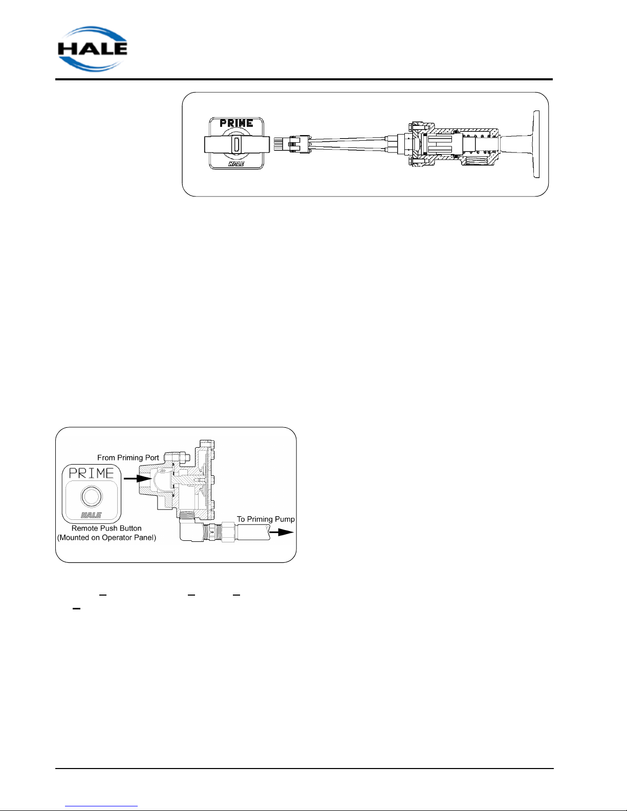
Priming Valves
Booster Pumps
Figure 1 -10: PVG Priming Valve
2. The Hale PVG Priming Valve (Figure 1 -
10) is mounted on the pump operator’s
panel. The PVG is a combination valve and
switch. When the handle on the PVG is
pulled out, the valve opens and the switch
energizes the primer motor. Pushing the
handle de-energizes the motor and closes
the valve.
Hale priming valves open when the priming
pump is operated to allow the air to escape from
the pump. There are two priming valves
available:
Figure 1 -9 : SPVR Priming Valve
1. Hale Semi-Automatic Priming Valve for
Remote Mounting (SPVR) A hose is
connected from the SPVR to the priming tap
on the booster pump body. When the SPVR
is installed, a single push-button on the
operator’s panel starts the priming pump
motor. When a vacuum is created, the
SPVR opens. Releasing the push-button
stops the priming pump and the SPVR
closes. Figure 1-9
Pressure Control
The P Series relief valve system is a bronze,
variable-pressure setting relief valve that
prevents undue pressure per the requirements
of NFPA Standard 1901. An indicator light on
the operator control panel signals when the
valve is open.
The P Relief Valve System
The P relief valve system consists of a panel
mounted control valve (PM) and, depending on
the pressure rating of the pump, a P30, or P35
relief valve mounted in the discharge piping and
plumbed back to the pump suction. Valve
connections are either flanged or Victaulic tm.
Both are shown in figure 1-12.
How the Relief System Works:
A bleeder line mounted in the pump discharge
pressure tap provides pressure to the
diaphragm in the PM control valve. The
handwheel on the PM control either increases
or decreases the spring tension on the
diaphragm. The seat of the P-series relief valve
is kept closed by pump discharge pressure.
Sec I- 6
As pump pressure increases, more pressure is
Introduction

Booster Pumps
applied to the diaphragm in the PM Control
valve. As the pressure on the diaphragm
increases beyond the set point, the stem will
move off its seat, allowing pump pressure to
push on the piston in the relief valve. The
pressure on the piston will cause the relief valve
seat to lift
allowing
excess
pressure to
dump back to
the pump
suction. After
the pressure
equalizes, the
piston returns
to the closed
position.
Figure 1-11: TRV-L
The amber
indicator light on the PM control illuminates
when the relief valve is open.
Thermal Relief Valveb (TRV)
The Thermal Relief Valve (see Figure 1-11)
protects the pump from overheating. The
optional TRV unit can be attached to the
discharge piping either by flange mounting or 11/4" NPT threaded connection (38 mm for the
TRVM). The valve monitors the temperature of
the water in the pump. When the temperature
exceeds 120o F (48.9o C), the valve
automatically opens and depending on the
installation, discharges a small amount of water
either to the ground or into the water tank
allowing cooler water to enter. After the
temperature returns to a safe level, the valve
closes. The TRV will flow up to 1-2 GPM (3-7
LPM).
TRV-L Kit
The TRV-L kit includes a chrome panel placard
with a warning lamp, lamp test button, and a
preassembled wiring harness. The light
illuminates whenever the TRV is open and
discharging water. An optional buzzer provides
audible warning. The buzzer mounts on the
operator panel.
Anodes
The Hale Anode System
helps prevent damage
caused by galvanic corrosion
in the pump. Galvanic action
pits the pump and pump
shaft material. The popularity
of non-corrosive water tanks
and piping has increased this
type of corrosion in today’s
fire pumps. The Hale Anode
System is a sacrificial metal, which helps
prevent corrosion. The anode will fit on any
Hale truck mounted pump, regardless of age or
model. It is designed to be easily installed
requiring four bolts and a gasket. Total time to
install is just fifteen minutes, yet it will provide
years of protection for the pump. The Anode kit
is designed for installation in the standard Hale
115 series flange opening. On fabricated
manifolds and similar applications, the installer
is to provide 1-1/4 NPT openings and install
anodes directly. It is recommended that one
anode be installed on the suction side and one
on the discharge side.
Figure 1-13:
Hale Anode
Figure 1-12:
Introduction
Sec I-7

Booster Pumps
EXPLANATION OF TERMS
Atmospheric Pressure
Static air pressure. Air pressure is 14 pounds
per square inch at sea level. Pressure increases
below sea level and decreases above sea level.
The weather also effects air pressure. Air in a
high pressure area compresses and warms as it
descends. The warming inhibits the formation of
clouds, meaning the sky is normally sunny in
high-pressure areas. But haze and fog still
might form. Just the opposite occurs within an
area of low atmospheric pressure. Atmospheric
pressure effects a pumps ability to pump from
draft. Higher pressures will increase a pumps
performance, while lower pressures can cause
a noticeable decrease in lift.
Cavitation
The sudden formation and collapse of lowpressure bubbles in liquids by means of
mechanical forces, such as those resulting from
rotation of a pump impeller.
Priming Pump
An auxiliary positive displacement pump which
pumps air out of the booster pump creating a
vacuum in order to prime the pump. The
priming pump is a rotary vane type, electric
motor driven. Once the main pump is primed
and pumping, the priming pump is shut off.
Relief Valve
An automatic valve which, when activated by
the relief valve control will hold the pump
pressure to no more than 30 PSI when the
pump discharge is gated or closed. The valve
maintains a set pressure by diverting the pump
discharge flow into the pump suction.
Relief Valve Control (PM)
A hand adjustment valve. When set to the
desired pressure, the relief valve will maintain
the desired pump discharge pressure and limit
a pressure increase to no more than 30 PSI (2
BAR).
Dead Heading
Operating a pump without any discharge. Lack
of flow causes temperatures to rise inside the
pump.
Impeller
The working part of centrifugal pumps which
imparts energy (motion) to the water.
Essentially, an impeller consists of two discs
separated by curved vanes. The vanes force
the water to rotate between the discs and is
thrown outward at high velocity. The water from
the impeller discharges into a diverging
passage known as a volute, converting the high
velocity energy of the water into pressure.
Volute
The increasing discharge path of the pump, its
function is to collect the water from the impeller
and depending on its design can either increase
pressure and decrease velocity or increase
velocity and decrease pressure.
Sec I- 8
Introduction
Booster Pumps
SECTION II OPERATING
PROCEDURES
This section supplies information and
procedures for the operation of Hale booster
pumps. Included in this section are procedures
for pumping from an on-board tank, a hydrant,
from draft, and post-operation procedures.
Unless otherwise indicated, these instructions
apply to all Hale booster pumps.
THE PROCEDURES IN THIS SECTION ARE
GENERAL OPERATING PROCEDURES. THEY
DO NOT REPLACE LOCAL PROCEDURES OR
POLICIES, NOR DO THEY REPLACE THE
RECOMMENDATIONS AND PROCEDURES
PROVIDED IN THE TRUCK MANUAL.
STATIONARY PUMPING OPERATIONS
Pumping From a Hydrant
(General Operation)
1. Position the truck for the best hydrant hookup
and discharge hose layout.
REFER TO DEPARTMENT PROCEDURES
FOR SETTING WHEEL CHOCKS AND LAYING
OUT SUCTION AND DISCHARGE HOSES.
ALL VALVES, DRAIN COCKS, AND CAPS
SHOULD BE CLOSED.
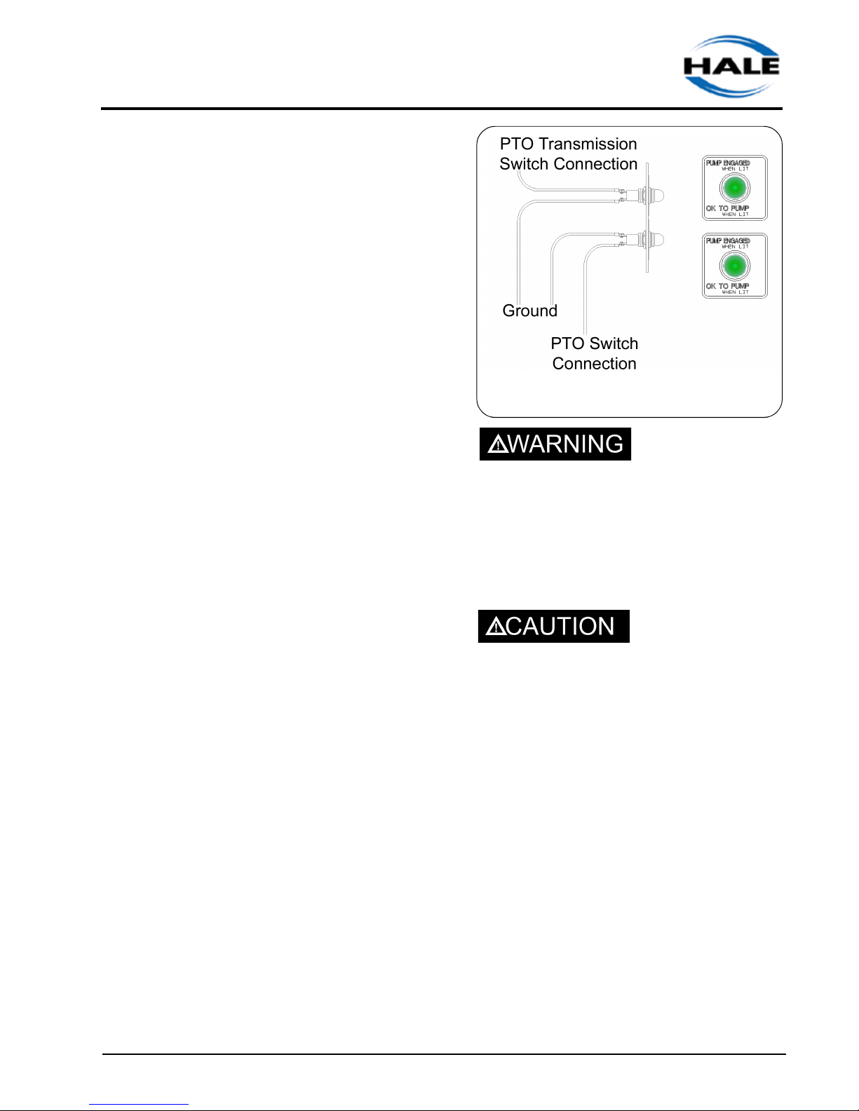
Figure 2-1: Driver's Compartment
Indicator Lights
DO NOT LEAVE THE CAB OR ATTEMPT TO
PUMP UNTIL ALL "OK TO PUMP" LIGHTS IN
THE CAB ARE ILLUMINATED. (Figure 2-1).
6. Exit the driving compartment only after all the
above steps are completed.
DO NOT OPEN THE THROTTLE UNLESS
THE GREEN INDICATOR LIGHT IS ON
(Figure 2-2).
7. Verify the pump panel shift indicator light is
on and that all hose connections are complete.
2. Bring the truck to a complete stop before
attempting to shift from "road" to "pump".
3. Apply the truck parking brake.
4. Shift the truck transmission to the NEUTRAL
position.
5. Engage the pump PTO switch.
Operating Procedures
8. Open the hydrant. Bleed off the air from the
suction hose.
9. Open the suction valve.
10. If necessary to eliminate air pockets, prime
the pump; see Pumping From Draft for
instructions.
Sec II- 1
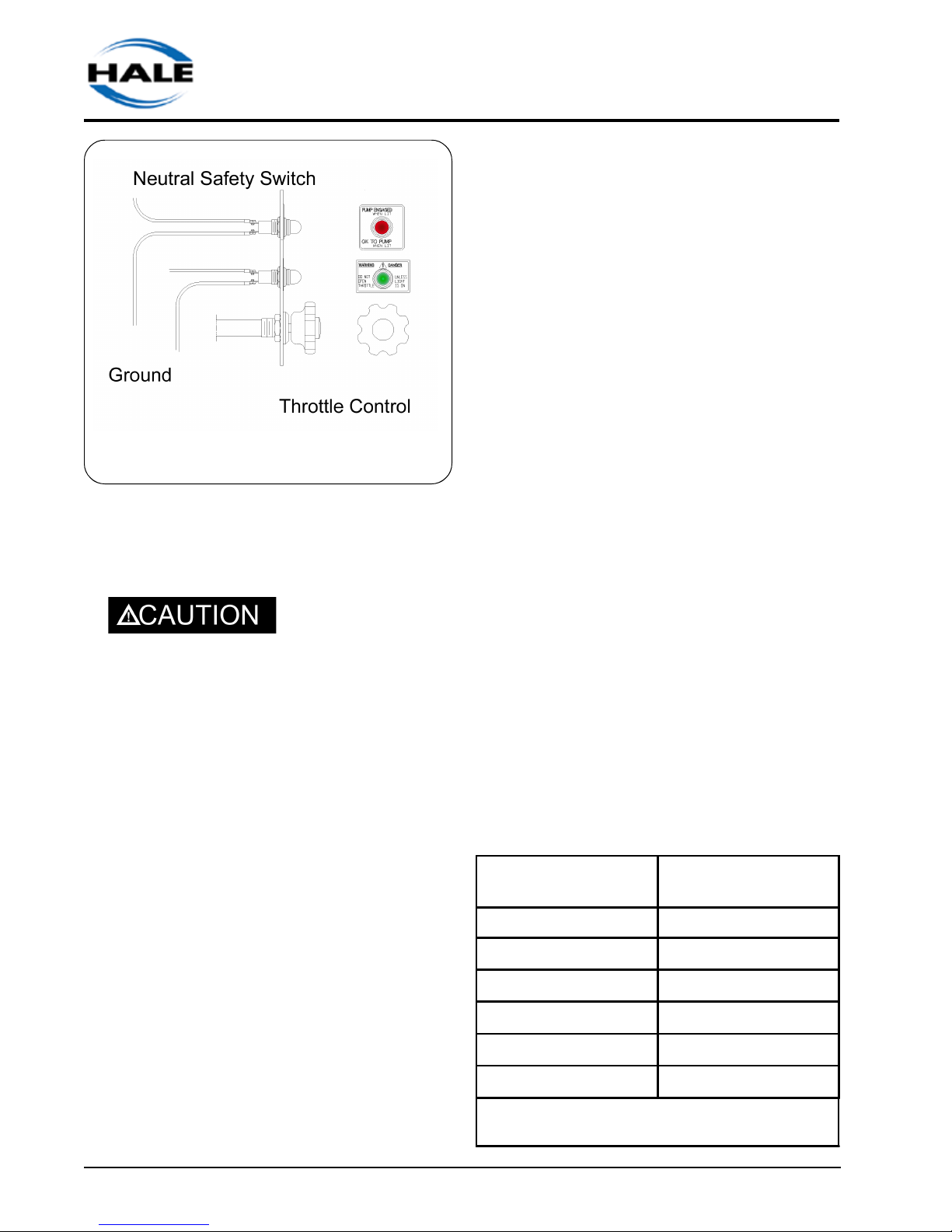
Figure 2-2: Pump Operator's Panel
11. Advance the engine throttle gradually until
the master discharge gauge indicates the
desired pressure.
DO NOT REDUCE THE PRESSURE ON
THE INTAKE GAUGE BELOW ZERO;
SERIOUS DAMAGE TO THE WATER MAIN
COULD RESULT.
The master intake gauge reading must be
maintained at 5 PSI (.3 BAR), minimum. If the
gauge shows a vacuum the pump is attempting
to draw more water than the hydrant can
supply. When this occurs, reduce the pump flow
to increase the pressure.
As the throttle is opened, the pressure gauge
reading increases with the engine speed. If the
engine speed increases without an increase in
pressure, the pump is beginning to cavitate.
Close the throttle slowly until the pressure
begins to drop, and the engine returns to an idle.
Booster Pumps
13. If the pump overheats and it is not equipped
with a Hale TRV valve, open the valve to
access the bypass line, if it is furnished, or
open the valve to the booster tank (both
suction and discharge sides) to circulate
water.
14. After completion of pumping operations,
gradually reduce the pump pressure until the
engine is at idle speed. Disengage the PTO.
DRAFT LIMITING F ACT ORS
The effect of raised water temperatures when
pumping from a positive pressure source
(hydrant) is negligible on fire pump
performance. But when pumping from draft,
elevated water temperature does have a limiting
effect. Water temperatures above 95o F (35o C)
will cause a noticeable decrease in lift when
drafting. Another factor that can limit lift when
drafting is barometric pressures below 29 In of
Hg. It is important to be aware of environmental
conditions when drafting.
PUMPING FROM DRAFT
1. Get as close to the water source as possible.
The pump can draw 100% of its rated capacity with less than a 10 foot vertical lift. As the
lift increases to above 10 feet, the pump
Water Temperature
Fo (C)
60° (16°) NFPA Baseline
70° (21°)
80° (27°)
90° (32°)
Lift Loss
Head Ft (Meters)
.3 (.09)
.6 (.18)
1.1 (.335)
12. Set the automatic relief valve according to
department policy. If no department policy
exists, refer to the Relief Valve Procedures
later in this section.
Sec II- 2
100° (38°)
110° (43°)
Table 2-1 : Additional Losses Beyond
Baseline NFPA Rating
1.7 (.52)
2.5 (.76)
Operating Procedures

Booster Pumps
capacity will be reduced.
2. Bring the truck to a complete stop.
3. Apply the truck parking brake.
4. Shift the truck transmission to the NEUTRAL
position.
REFER TO DEPARTMENT PROCEDURES
ON SETTING WHEEL CHOCKS AND HOSES.
ALL VALVES, DRAIN COCKS, AND CAPS
SHOULD BE CLOSED.
5. Engage pump PTO.
DO NOT LEAVE THE CAB OR ATTEMPT
TO PUMP UNTIL ALL THE INDICATOR
LIGHTS IN THE CAB ARE ON.
6. Exit the driving compartment only after all the
above steps are completed and the indicator
lights in the cab and on the panel are on.
DO NOT ADVANCE THE THROTTLE
UNLESS THE "OK TO PUMP" INDICATOR
LIGHT IS ON.
Running the engine at speeds higher than
1200 RPM during priming is not recommended since it will not improve priming
operation and may cause damage to the
pump.
IF THE DISCHARGE GAUGE READING DOES
NOT INCREASE, THE INTAKE GAUGE
READING DOES NOT FALL BELOW ZERO,
OR THE PRIMING PUMP DOES NOT
DISCHARGE WATER TO THE GROUND IN 30
TO 45 SECONDS, DO NOT CONTINUE TO
RUN THE PRIMING PUMP. STOP THE PUMP
AND CHECK FOR AIR LEAKS OR POSSIBLE
PUMP TROUBLE.
10. Gradually open the discharge valve until
water emerges in a steady stream. Then
open the other discharge valves to the
desired setting.
11. Open the engine throttle gradually until the
desired pressure or flow is reached.
As the throttle is opened, increase the pressure
gauge reading with engine speed. If the engine
speed increases without an increase in
pressure, the pump is nearing cavitation.
Cavitation will be discussed in detail later.
Reduce the flow from the pump to maintain
pressure or reduce the pressure (throttle) to
maintain flow.
7. Verify the pump panel shift indicator light is
on.
8. Activate the priming pump by pulling the
control handle located on the pump panel.
9. Monitor the intake and discharge master
gauges. The pump is primed when the
intake indication reading falls below zero,
and the discharge pressure starts to increase. Water may also be heard discharging to the ground.
Operating Procedures
13. If a pump shutdown is desired while pumping
from draft, reduce the engine speed to idle,
and close the discharge valves. To resume
pumping, open the throttle and discharge
valves.
14. Set the automatic relief valve according to
department policy. Refer to the Relief Valve
Procedures later in this section.
15. If the pump overheats and is not equipped
with the Hale TRV valve, open the valve to
access the pump auxiliary cooling system, or
Sec II- 3

Booster Pumps
slightly open the drain line.
16. After completing pumping procedures,
gradually reduce the engine RPM to idle
speed and disengage the PTO.
PUMP AND ROLL OPERATION
Hale booster pumps are primarily driven by a
transmission mounted Power-Take-Off (PTO)
unit.
During pump and roll operation, it is necessary
to slow the forward motion of the apparatus to
the PTO manufacturer's recommended
engagement speed.
The following outlines a general pump and roll
procedure:
1. Slow the apparatus to safe PTO engagement
speed as recommended by the PTO manufacturer.
Note: Most PTOs must be engaged while the
apparatus is stopped. Only a "Hot Shift" PTO
can be engaged while the apparatus is rolling.
2. Engage the PTO.
RELIEF VAL VE PROCEDURES
TPM /P35 Relief Valve Procedures
These procedures cover the Hale TPM Relief
Valve System. Be sure to select the correct
procedure, for the equipment on the truck.
1. Set the pressure indicator on the PMD
control valve to a position slightly above the
normal operating pressure (even before
water starts to flow).
2. After normal operating pressure has been
achieved (as indicated on the master pressure gauge while the pump is discharging
water), slowly move the adjusting hand
wheel counterclockwise until the relief valve
opens, and the amber indicator light comes
on.
3. Turn the hand wheel slowly clockwise until
the indicator light goes out. The relief valve
will operate at the set pressure.
4. When the pump is not in operation, turn the
hand wheel clockwise back to a position
slightly above the normal operating pressure.
3. Verify the PUMP ENGAGED light is illuminated.
4. Open the valve between the tank and pump
suction.
5. Observe pump discharge pressure and verify
the pump pressure increases.
6. Prime the pump if necessary.
7. Open the discharge valves and commence
operations.
Sec II- 4
Figure 2-3 PMD Relief
Valve Control
Operating Procedures

Booster Pumps
More complete and detailed information can
be found in the relief valve manual.
THE PRESSURE INDICATOR ON THE
PANEL IS ONLY A ROUGH INDICATION
OF TPM SETTING. ALWAYS USE THE
ABOVE PROCEDURE TO PROPERLY SET
THE TPM RELIEF VALVE SYSTEM.
CAVITATION
Cavitation can occur while pumping from draft,
in relay, or from a hydrant. The operator must be
aware of the warning signs and correct the
situation, or serious damage to the pump and
impeller will occur.
Cavitation can damage the impeller and other
sensitive components, impair pump
performance, and reduce flow capacity. The
damage done during any one period of
cavitation is not great, but the effects are
cumulative. Implosions occurring during
cavitation break away or erode tiny pieces of
metal from the internal parts and the pump
casing. When enough metal has been chipped
away, the impeller becomes unbalanced
causing a strain and vibration on bearings,
bushings and shafts.
Process of Cavitation
1. When increased discharge demand exceeds
the intake, bubbles form in the low-pressure
region (eye) of the impeller.
2. The pressure of the water in the pump drops
as it flows from the suction flange through
the suction nozzle and into the impeller.
3. As flow from the pump increases, the
vacuum at the impeller increases. As the
vacuum increases, the boiling point of water
in that vacuum decreases until it reaches a
point near the impeller eye where it boils and
vaporizes.
4. Once the vapor pockets, or bubbles, enter
the impeller, the process begins to reverse
itself. As the vapor reaches the discharge
side of the pump, it is subjected to a high
positive pressure and condenses back to a
liquid.
The way to eliminate cavitation is to increase the
flow to the pump, decrease the amount of water
being discharged from the pump, or reduce the
pressure in the pump by decreasing engine
speed.
Cavitation
Cavitation occurs when a centrifugal pump is
attempting to discharge more water than it is
receiving. It is often referred to as “the pump
running away from the supply."
Operating Procedures
Figure 2-4 Low Pressure Regions
5. The sudden change from vapor to liquid
generates a shock effect that damages the
impeller and pump housing. Usually there
are thousands of tiny vapor pockets
(bubbles) rather than a few large ones. It is
the collapsing (or implosion) of these
bubbles that causes the characteristic sound
of cavitation that has been described as
rocks tumbling in the pump.
Sec II- 5

Booster Pumps
Warning Signs of Cavitation: Discharge
and Gauges
Discharge Pressure
In a properly functioning pump, an increase in
RPM will increase the discharge pressure and
volume. An increase in engine RPM that does
not cause an increase in the pump discharge
pressure, is the most reliable indication that a
pump is approaching cavitation.
Vacuum Compound Gauge
The operator should not depend entirely on the
vacuum (compound) gauge to indicate when a
pump is nearing cavitation: The vacuum gauge
is usually tapped into the intake chamber
several inches away from the leading edge of
the impeller eye where the greatest amount of
vacuum occurs. The vacuum gauge does not
take into account ambient temperature nor
atmospheric pressure and is not accurate near
zero on the vacuum scale.
illustrates the amount of lift loss as
temperatures rise. If there is a marked loss
of suction capacity, the pump may be near
cavitation.
NOTE: When water reaches 95° F( 35 C),
the operator is likely to notice a marked
decrease in lift.
o Monitor barometric pressure. NFPA
standards sets a baseline of 29.9”Hg. See
Table 2-2.
o Location: The higher the elevation above
sea level, the lower the atmospheric
pressure and less lift. See Table 2-3.
o Open the throttle gradually and watch the
Barometric Reading
in (mb)
29.9 (1012.53) NFPA Baselines
29.7 (1005.76) .2 (.06)
Lift-loss in Head Feet
(meters)
How to Prevent Cavitation
A soft sleeve has an advantage over a hard
sleeve when pumping from a hydrant because it
will partially collapse providing an immediate
indication to the operator that cavitation is
imminent. A hard sleeve indicates problems only
at the intake gauge which is not the best or most
reliable indicator.
Monitoring current operating conditions,
knowing the capabilities of the equipment, and
regular inspection are the best protection
against cavitation.
During Operations:
o Do not increase the pump speed beyond the
speed at which the pressure ceases to rise.
o Monitor the water temperature baseline per
NFPA standards is 60° F (16 C). Table 2-1
29.5 (999) .5 (.15)
29.3 (992.21) .7 (.21)
29.1 (985.444) .9 (.27)
28.9 (978.67) 1.1 (.33)
28.7 (971.89) 1.4 (.43)
Table 2-2 : Lift-Loss from Barometric Pressure
pressure gauge and the tachometer, if
equipped. An increase in engine RPM
without a corresponding increase in
pressure indicates cavitation.
o Use a hard suction hose when pumping from
draft and soft suction hose when pumping
from hydrant.
Preventive Measures:
o Regularly inspect discharge and suction
hoses to check for air leaks: these can also
Sec II- 6
Operating Procedures

Booster Pumps
Elevation
Feet (Meters)
Lift-Loss in Feet
(Meters)
2,000 (609) NFPA Baseline
3,000 (914) 1.1 (0.33)
4,000 (1219) 2.2 (0.67)
5,000 (1524) 3.3 (1)
6,000 (1828) 4.4 (1.34)
7,000 (2133) 5.5 (1.67)
8,000 (2438) 6.6 (2.01)
9,000 (2743) 7.7 (2.35)
10,000 (3048) 8.8 (2.68)
Table 2-3: Lift Loss from Elevation
cause cavitation.
o Consider the size of the suction hose: Table
2-4 shows the NFPA pre-selected hose
sizes for each pump-rating capacity. Using
the appropriate-sized hose will minimize the
occurrence of cavitation.
Hose
Diameters
(mm)
FLOWS GPM
(LPM)
250
350
500
750
1000
1250
1500
1750
2000
2500
Table 2-4: Hose Sizes for Pump-Rating Capacity
3"
(76)4"(102)
5.2
(19.7)
2.5
(9.5)
5.0
(19)
11.4
(43)
4 ½"
(114)5"(127)6"(152)
3.6
(51.5)
8.0
(30)
14.5
(55)
Lift Loss
(17.8)
4.7
8.5
(32)
13
(49)
1.9
(7.2)
3.4
(12.9)
5.2
(19.6)
7.6
(28.7)
10.4
(39.4)
Dual
6"
1.9
(7.2)
2.6
(9.8)
3.4
(12.9)
5.2
(19.6)
o Consider the piping within the truck: Further
suction losses may result from additional
suction piping added to the fire pump during
assembly by the manufacturer.
o Follow the maintenance and inspection
procedures.
o Cavitation can occur with large nozzle tips.
Solve this problem by reducing flow.
o Cavitation can also occur when air enters the
pump. The pump may be primed, however,
air leaks can cause rough operation and an
increase of engine speed without an increase in pressure or flow. If an air leak is
suspected, discontinue pumping and refer to
Section IV.
Operating Procedures
Sec II- 7

POST OPERATION PROCEDURE
o Return the engine to idle.
o Slowly close all valves.
o Place the transmission in neutral or park.
o Slowly shift from "pump" to "road" to disen-
gage the pump.
o Drain the pump (especially important in
freezing weather):
a. Open the discharge valves, remove
suction tube caps, and discharge valve caps.
b. Open the pump body drain cocks or Hale
multiple drain valve. If a multiple drain valve
is used, all pump drain lines should be
connected to this valve.
Booster Pumps
c. After the pump is completely drained,
replace all caps and close all valves,
o If sea water, dirty water, alkaline water
or foam solution, has been used, flush the pump
with clean water.
o Remove the wheel chocks only when
preparing to leave the scene.
o Fill out the pump run log, indicating total
pumping time and total out-of-station time.
o Report all pump, vehicle and equipment
malfunctions, and irregularities to the proper
authority.
o Know and follow all local procedures.
Sec II- 8
Operating Procedures

Booster Pumps
SECTION III PREVENTIVE
MAINTENANCE
OVERVIEW
Hale Booster Pumps require very little care and
maintenance. However, the little required is
important. Preventive maintenance tasks take
little time to accomplish and consist of leak
testing, lubrication and cleaning. The
procedures supplied in this section are for
normal use and conditions.
This section provides recommended actions to
be completed after each use, weekly, monthly
and annually basis.
Post-Operation Maintenance Procedures
Flush Pump
1. Inspect the suction hose and rubber washers
as well as the washers in the suction tube
caps. Remove any foreign matter from the
hose and coupling. Replace worn, damaged, or dry washers.
2. Verify all discharge valves, drain valves and
drain cocks are closed.
o Checking and cleaning the intake strainers
o Checking any auxiliary engine.
o Verifying all gauges are in working order.
o Operating pump controls.
o Inspecting water and foam tanks.
o Checking roof and bumper turrets
o Checking auxiliary fire suppression equip-
ment
Relief Valve Testing
When the relief valve is not in operation, keep
the hand wheel set above the normal operating
pressure.
1. Set up to pump from the
onboard water tank with
the discharge flow back to
the water tank.
2. Turn the relief valve hand
wheel clockwise to the
stop to prevent the relief
valve from operating.
Figure 3-1
3. Tighten the suction caps.
Weekly Maintenance
Weekly maintenance consists of:
o Testing the relief valve system
o Testing the priming system
o Testing the pump shift warning indicator
lights
o Valve Maintenance
Preventive Maintenance
3. Bring the pump pressure
up to 150 PSI (10 BAR) as
indicated on the master
pressure gauge per
normal operating procedures.
4. Turn the relief valve hand wheel counterclockwise until the relief valve opens. The
relief valve is open when the amber indicator
light is lit and the pressure begins to drop.
5. Turn the relief valve hand wheel clockwise
then counterclockwise a few times to ensure
that the hand wheel turns freely. Observe
the pressure gauge and indicator light for
Figure 3-1
PM Valve Control
Sec III- 1
 Loading...